Futurecom PDR8000 Manual
Portable digital repeater product planner
Hide thumbs
Also See for PDR8000:
- Programming manual (98 pages) ,
- Deployment manual (35 pages) ,
- Programming manual (86 pages)

Subscribe to Our Youtube Channel
Related Manuals for Futurecom PDR8000


Summary of Contents for Futurecom PDR8000
- Page 1 Futurecom Systems Group, ULC ® PDR8000 Portable Digital Repeater Product Planner Document: 8K088X02 Revision: R5.0 Date: 2021-11-15...
- Page 2 No part of this document, or any software included with it, may be reproduced and distributed without the prior written permission of the copyright holder. Futurecom Systems Group, ULC reserves the right to make changes or improvements to the equipment, software or specification described in this document at any time and without prior notice.
-
Page 3: Table Of Contents
Document 8K088X02 R5.0 PDR8000® Portable Digital Repeater Product Planner Table of Contents Introduction ......................9 Key Features & Benefits ..................9 Applications ...................... 10 PDR8000 Hardware form factors ................ 11 PDR8000 Suitcase ................... 11 2.1.1 Internal Duplexer ....................12 2.1.2 Simplex ........................12 2.1.3... - Page 4 6.6.2.1.3 Rx NAC Operation: Community Repeater ..........41 6.6.2.1.4 Rx NAC Operation: Multi NAC ..............41 Data Services ....................42 Adaptive Power Control ................... 42 Service/Configuration Software (Futurecom Repeater Configurator (FRC)) ..43 6.10 Status Indication LEDs ..................43 6.10.1 Front Panel Indicators ..................44 6.10.2...
- Page 5 6.12.1 Optional External Battery Pack ................47 6.13 Suitcase/Housing ..................... 48 6.14 External Ports - PDR8000 Suitcase ..............49 6.15 External Ports - Booster Pack ................51 6.16 Open/Closed Case Operation (Suitcase Only) ..........52 6.17 Zippered Accessory Pouch ................52 6.18 RT/RT Configuration (V.24 interface only) ............
- Page 6 Figure 31: Booster Pack External Ports ..................51 Figure 32: Zippered Accessory Pouch ..................53 List of Tables Table 1: Duplexer Specifications for PDR8000 Suitcase ............12 Table 2: Duplexer Specifications for Rackmount PDR8000 ............16 Table 3 - PDR8000 RF Configuration ..................25 Table 4: Analog Access Code Table ..................37 Table 5: Digital Access Code Table ..................40...
- Page 7 It isolates the receiver from the transmitter while permitting them to share a common antenna. Full-Duplex Bidirectional simultaneous communications Fallback In-Cabinet Repeat: A mode of operation when PDR8000 FBICR activates a local-repeat function if it’s wireline link becomes impaired Futurecom Repeater Configurator: The application for configuring...
- Page 8 Transmit A digital link better described as a physical V.24 link with HDLC (High- V.24 level Data Link Control). Used to connect PDR8000 to other infrastructure elements (e.g. CCGW, DIU, comparator) Communication system elements that observe multiple received Voting / Comparator signals, and choose the best (highest quality) to present to receiving users.
-
Page 9: Introduction
Connect to your dispatch console wherever it may be via a V.24 (for P25) or Ethernet IP (Analog or P25) connection. The platform the PDR8000 is based on, has been in the field since 2006. Known generically as the DVR (Digital Vehicular Repeater), this platform has an installed base of 30,000+ units serving public safety first responders worldwide. -
Page 10: Applications
Document 8K088X02 R5.0 PDR8000® Portable Digital Repeater Product Planner • LCD screen & keypad allow easy access to Channel Change and other features * Only available in Suitcase model 1.2 A PPLICATIONS • Special events • Interoperability • Dignitary protection •... -
Page 11: Pdr8000 Hardware Form Factors
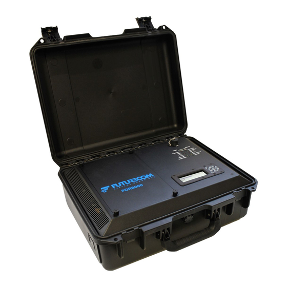
2.1 PDR8000 S UITCASE PDR8000 suitcase form factor is typically a self-contained device but is easily modified to utilize an alternate duplexer and/or a transmit power Booster Pack when required. Different RF hardware combinations are supported, using accessible internal and external connection points to enable the desired configuration. -
Page 12: Internal Duplexer
10 MHz Table 1: Duplexer Specifications for PDR8000 Suitcase Note that the following diagrams illustrate the adaptability of PDR8000 suitcase by use of its internal and external connection points. These diagrams do not represent a detailed view of the circuitry within each of the elements. -
Page 13: Simplex With Booster Pack
Document 8K088X02 R5.0 PDR8000® Portable Digital Repeater Product Planner 2.1.3 S IMPLEX WITH OOSTER Figure 6: Simplex with Booster Pack Hardware Topology 2.1.4 I NTERNAL UPLEXER AND OOSTER Figure 7: Internal Duplexer and Booster Pack Hardware Topology 2.1.5 E XTERNAL... -
Page 14: External Duplexer And Booster Pack
2.1.7 B OOSTER PDR8000 natively provides a pre-duplexer output power configurable up to 20 watts. If higher output power is needed, configurations using an external Booster Pack can be utilized (see 2.1.3, 2.1.6). The Booster Pack configuration utilizes the standard PDR8000 suitcase hardware/software and adds an additional suitcase (same dimensions/colors as the PDR8000) which provides additional transmit power. -
Page 15: Rackmount Pdr8000
PDR8000 and its configuration software (Futurecom Repeater Configurator (FRC). Note that a Booster Pack can only be used with a PDR8000 built for the same RF band as the Booster Pack. Different order codes are used to purchase Booster Packs for each of PDR8000’s supported RF Bands. -
Page 16: Figure 12: Rackmount Pdr8000 Back Panel
Customer supplied external duplexers open the possibility of utilizing other frequency separation and bandpass width. Note that the following diagrams illustrate the adaptability of Rackmount PDR8000 by use of its internal and external connection points. These diagrams do not represent a detailed view of the circuitry within each of the elements. -
Page 17: Internal Duplexer
Document 8K088X02 R5.0 PDR8000® Portable Digital Repeater Product Planner 2.2.1 I NTERNAL UPLEXER Figure 13: Internal Duplexer Hardware Topology 2.2.2 I 50W P NTERNAL UPLEXER AND OWER MPLIFIER Figure 14: Internal duplexer with 50W Power Amplifier Hardware Topology 2.2.3 E... -
Page 18: Pdr8000 Use Cases
Wireline Satellite Transmitter or Receiver 3.1 W IRELINE EPEATER AND TATION This is the primary use case of PDR8000, where a PDR8000 is connected to an ASTRO system infrastructure, providing a means for fixed-end equipment 3.1.1 V.24 W IRELINE EPEATER... -
Page 19: Ethernet Wireline Repeater
PDR8000 can be connected to Motorola’s ASTRO system or Consoles via the Ethernet Wireline interface. Implemented on the industry standard commonly known as Digital Fixed Station Interface (DFSI) Protocol Version 1, PDR8000 can connect to a console (either directly or via a gateway) which supports this standard. -
Page 20: Back To Back Cross Band Repeater (Rt/Rt)
PDR8000 does not actively encode/decode MDC 1200, but does pass the signaling through its repeat path. Care should be taken when using MDC 1200 to ensure that PDR8000 has sufficient time to recognize the received RF signal, qualify its squelch (PL/DPL) and key up to repeat the signal. If MDC 1200 is received too quickly, its beginning may be truncated. -
Page 21: Wireline Satellite Receiver/Transmitter
Some user deployments require handling different coverage scenarios than typically provided by the PDR8000 Repeater configuration. Receive-only and Transmit-only capabilities are part of the suite of configurations supported by PDR8000 to allow customers to take advantage of these specialized solutions. These configurations are supported by PDR8000 operating in digital/P25 mode via the V.24 wireline interface only. -
Page 22: Deployment Profiles
RF frequencies. By utilizing the ten possible Deployment Profiles, PDR8000 can be ready to “pick up and go” for a large number of common use case scenarios. The PDR8000 can be configured to power-up to a specific Deployment Profile, or can boot to the “last active”... -
Page 23: Supported Functional Configurations
PDR8000® Portable Digital Repeater Product Planner 5 SUPPORTED FUNCTIONAL CONFIGURATIONS The functional behavior of a PDR8000 and its channels are defined by a multi-level set of configuration parameters. These parameters are modified using the PDR8000 configuration software tool, known as the Futurecom Repeater Configurator (FRC) (see 6.9). The range of... -
Page 24: Satellite Transmitter
(see 5.3.2), or full-duplex (see 5.3.1) channels. If a PDR8000 is configured with a combination of half-duplex/simplex and full-duplex channels, then only those channels consistent with the current Repeater Operation configuration can be enabled and available for use. -
Page 25: Repeater
Enabled, Local Repeat Disabled, or revert to the state previously requested by a console (locally cached within the PDR8000). It is also possible to configure a PDR8000 to automatically activate Repeat mode in the case of certain system outages. (This operation is known as Fallback In-Cabinet Repeat; see 6.5.) When a PDR8000 is receiving RF-sourced information and repeating it back over-the-air, it keeps its transmitter active for a configurable amount of time after the received signal stops. -
Page 26: Base Station
In system configurations that depend on Repeat functionality being provided by an external entity (e.g. comparator or console), it is often desired to utilize a backup mode in the PDR8000 to provide Repeat functionality should the external repeating entity fail, thus allowing subscriber units to continue communicating with each other through a backup repeat mechanism. -
Page 27: Half-Duplex (& Simplex)
Other customers may want to allow the conflict, which gives the second talker some chance of being heard in a situation deemed critical by the user. The PDR8000 is also configurable as to whether it should allow a wireline-sourced transmission to occur when other activity is being received on the CAI. -
Page 28: Illustrative Examples
LLUSTRATIVE XAMPLES – H 5.4.1 B TATION UPLEX CHANNEL Antenna • Full-Duplex wireline interface • PDR8000 Transmits OR Receives at a moment in time - OR - PDR8000 Wireline Interface System Infrastructure Figure 21: Half-Duplex Base Station Example – F 5.4.2 B... -
Page 29: Repeater With Infrastructure
Document 8K088X02 R5.0 PDR8000® Portable Digital Repeater Product Planner 5.4.3 R EPEATER WITH NFRASTRUCTURE Repeater with wireline interface RF Signals RF Signals Antenna Antenna • Full-Duplex wireline interface • PDR8000 can transmit and receive simultaneously • PDR8000 provides Local Repeat... -
Page 30: Product Capabilities
ULTIPLE HANNELS PDR8000 is capable of being programmed for up to 64 different Conventional channels in each of its Deployment Profiles (see section 4). Any one of these may be selected for use at a given time. The currently active channel can be initialized via configuration parameters, and later be modified via commands from a console via the wireline interface, if so connected. -
Page 31: Transmit Power Level
Power output provided by PDR8000 when transmitting on this channel. The configured power (1-20 watts) is provided at the output of the PDR8000 internal Tx port. This port is further connected to an antenna, internal duplexer, external duplexer, or transmit Booster Pack. Each entity connected affects the output power by attenuating or boosting the signal. -
Page 32: Bsi (Base Station Identication)
Rx: 806 - 824 MHz, and 851 - 869 MHz to monitor direct subscriber-to-subscriber activity There is a different model of PDR8000 for each of the above RF frequency bands. A specific order code is available for each. 2021-11-15... -
Page 33: Wireline Interfaces
IRELINE NTERFACE PDR8000 is equipped with a V.24 wireline interface allowing it to optionally be connected to other Futurecom & Motorola equipment supporting Motorola’s AIS protocol over V.24. Connections may be to another PDR8000 or Motorola station to support an RT/RT configuration (see 3.2), or to a system infrastructure including consoles, data interface, and/or a voting... -
Page 34: Transmit Clock Synchronization
When a PDR8000 receives an infrastructure message on the V.24 wireline interface, it processes the message if the message’s TEI is set to the “Broadcast” value or to the TEI/Site configured into the PDR8000. If a message is received by PDR8000 that is directed to any other TEI, the message is ignored. -
Page 35: Dfsi Features
Repeat functionality normally provided by the system is curtailed due to an unexpected event. If the PDR8000 gets disconnected from the comparator or console, the PDR8000 can temporarily activate its own Fall Back In-Cabinet Repeat functionality to allow subscriber-to-subscriber communications to continue. -
Page 36: Squelch And Channel Access
PDR8000 determines whether the received signal should be accepted and processed (and thus repeated over-the-air and/or to the wireline connection). This ensures that the PDR8000 only passes along traffic of sufficient quality, and intended for the correct listeners. -
Page 37: Multi-Coded Squelch (Pl/Dpl)
PLs/DPLs. These behaviors are captured in Access Code Tables. Each configured channel in the PDR8000 can point to one of the configured analog Access Code tables. Each table can be used to define PL/DPL operation for a specific channel, or may capture behavior shared by multiple channels. -
Page 38: Multi-Coded Squelch: Normal (Multi-Pl/Dpl Not Enabled)
The PDR8000 only processes analog signals received over the air with PL or DPL that is equal to the Rx PL/DPL code entry found in the first row of the table. In the first row, if the Rx Squelch Code is set to OFF (Carrier Squelch), then all received signals on that channel that meet the Signal Strength and/or Signal Quality criteria (see 6.6.1) defined for this channel are processed... -
Page 39: Digital Signal Squelch & Access Operation
NACs. These behaviors are captured in Access Code Tables. Each configured channel in the PDR8000 can point to one of the configured Access Code Tables. Each Access Code Table can be used to define NAC operation for a specific channel, or may capture behavior shared by multiple channels. -
Page 40: Rx Nac Operation: Normal
If the active PDR8000 channel is programmed for Rx NAC Operation of Normal then the PDR8000 only processes messages received over the air with Rx NAC that is equal to the PDR8000’s configured Rx NAC found in the first enabled row of the Multi-NAC table. (Packets received with other NAC values are ignored.) When the PDR8000 sends a transmission, it... -
Page 41: Rx Nac Operation: Receiver Monitor
PDR8000 receives all incoming transmissions (regardless of NAC embedded in the received packet). If this PDR8000 is configured as a Repeater, it retransmits using the Tx NAC found in the first enabled row of the Multi-NAC table. Any infrastructure-originated (e.g., console) calls are also sent with Tx NAC from the first enabled row of the Multi-NAC table. -
Page 42: Data Services
Tx NAC to be used as part of the transmission information, or the console may defer to the PDR8000’s configured Tx NAC by specifying a Tx NAC of $F7E. It may be desired that console-originated transmissions utilize the previously received NAC code, to allow a dispatcher to reply to the previous call. -
Page 43: Service/Configuration Software (Futurecom Repeater Configurator (Frc))
TATUS NDICATION In order to provide a very high-level visual indication of the PDR8000’s status and health, a set of LED indicators is provided. One set of LEDs is inside the PDR8000 suitcase’s open lid, or the Rackmount PDR8000’s front panel, and the other indicator is on the PDR8000 suitcase’s side panel (adjacent to the external cable connections). -
Page 44: Front Panel Indicators
LINK RX: Indicates status and activity on the Receive Wireline (Ethernet or V.24) Interface o LOCAL RPT: Indicates whether PDR8000 is currently repeating due to initial configuration or received wireline command o DC/BATTERY: Indicates whether DC Power is normal, above/below operational threshold, or approaching lower threshold (configurable indication thresholds) o LINK QUALITY: Indicates the quality of the network (Ethernet or V.24 interface) -
Page 45: Side Panel Indicator (Pdr8000 Suitcase Only)
The Futurecom Repeater Configurator (FRC) application is used to retrieve logs that are saved in the PDR8000 and can also monitor real-time activity of the PDR8000 while it is actively processing radio traffic. -
Page 46: Local Ptt Tests
OCAL ESTS PDR8000 is equipped with a local PTT switch that can be used to help set up or test a field deployment. The PTT switch is accessed via a small opening (requiring insertion of an implement, to avoid accidental activation) on the PDR8000 front panel, just above the Status LEDs (see Figure 25). -
Page 47: Input Power Options And Indications
DFSI Parameters (IP Address, Ports etc.) If the PDR8000 is used in a location allowing it to be physically accessed by people who are not desired to view/modify data via the keypad/display, a Keypad Lockout mechanism is available to restrict access. -
Page 48: Suitcase/Housing
The Battery Pack can be used to supply DC power to a PDR8000 where an AC supply is not available. A fully charged, new Battery Pack can power a PDR8000 (at 50% transmit duty cycle) for 5 hours and can be recharged in approximately 10 hours from a fully-discharged state. -
Page 49: External Ports - Pdr8000 Suitcase
(lid open) of the case. The external connection points are illustrated below. Note that an LED Status indicator is included to indicate whether the PDR8000 is operating under normal/warning/error conditions. This indicator can be disabled via configuration in the Futurecom Repeater Configurator (FRC), as some users may want to operate in “dark mode”... -
Page 50: Figure 30: Pdr8000 External Ports
N Female Screw/Unscrew Dust Cap RF OUT N Female Screw/Unscrew Dust Cap RF IN N Female Screw/Unscrew Dust Cap Ground Lug 10-32x12.7mm (0.5") Green LED Indicator Connector was EGG.1K.306.CLL on releases prior to PDR8000 Release 4 2021-11-15 Page 50 of 64... -
Page 51: External Ports - Booster Pack
Document 8K088X02 R5.0 PDR8000® Portable Digital Repeater Product Planner Front Panel (lid open) Label Type Open/Close Mechanism USB Type B Screw/Unscrew Dust Cap Table 6: PDR8000 External Ports 6.15 XTERNAL ORTS OOSTER The Booster Pack also connects to its external environment via several connection ports. -
Page 52: Open/Closed Case Operation (Suitcase Only)
When operating open-case (providing the best cooling capability), the PDR8000 or Booster Pack is to be placed flat on its large surface. Note that the PDR8000 and Booster Pack are not water resistant when operating open-case. -
Page 53: Rt/Rt Configuration (V.24 Interface Only)
Document 8K088X02 R5.0 PDR8000® Portable Digital Repeater Product Planner deployment. This zippered pouch is buckled around the exterior of the PDR8000 case, and is easily removed during operation. Figure 32: Zippered Accessory Pouch 6.18 RT/RT C (V.24 ONFIGURATION INTERFACE ONLY The ability to connect a PDR8000 back-to-back with another repeater in order to allow cross- band or cross-frequency communication is explained in section 3.2. -
Page 54: Astro Fade Tolerance
Booster amplifier in-line during a transmission, but bypasses the Booster amplifier during receive. PDR8000 has an external Auxiliary port, which provides a control mechanism between the PDR8000 and a Booster Pack, as needed for some of the scenarios explained above (see example hardware topologies in 2.1.3 and 2.1.6). 6.20... -
Page 55: Purchasable Software Options
To facilitate this, each PDR8000 can be password-protected by its administrator. PDR8000 units are shipped without a password, but a password can be easily set within each PDR8000 using the Futurecom Repeater Configurator (FRC) application. Once a PDR8000 has a password set, it’s configuration data is protected, and can only be read from or written to the... - Page 56 Document 8K088X02 R5.0 PDR8000® Portable Digital Repeater Product Planner PDR8000 also allows real-time modification of certain operating parameters through its keypad/display (e.g. channel selection). Access to view/modify these parameters via the kepad/display can be restricted by configuring a unit-specific access code. (See 6.11.2 for details.)
-
Page 57: Pdr8000 Specification
800 MHz LO6-DVRSVHF LO6-DVRSUHF LO6-DVRS700 LO6-DVRS800 Industry Canada 2098B-DVRSVHF 2098B-DVRSUHF 2098B-DVRS700 2098B-DVRS800 Transmitter Specification 700 MHz 800 MHz Frequency Bands 136-174 MHz 380-430 MHz 764-776 MHz 851-869 MHz Connector was EGG.1K.306.CLL prior to PDR8000 Release 4 2021-11-15 Page 57 of 64... - Page 58 FM Hum and Noise 12.5kHz 37dB Connector was EGG.1K.306.CLL prior to PDR8000 Release 4 Specifications are typical and subject to change without notice. Futurecom Systems Group, ULC does not accept liability for any error or omission in this document. 2021-11-15...
-
Page 59: Booster Pack Specification Summary
380-430 MHz 764-776 MHz 851-869 MHz 450-470 MHz RF Output Power Specifications are typical and subject to change without notice. Futurecom Systems Group, ULC does not accept liability for any error or omission in this document. 2021-11-15 Page 59 of 64... -
Page 60: Rackmount Pdr8000 Specification Summary
Document 8K088X02 R5.0 PDR8000® Portable Digital Repeater Product Planner 7.3 R PDR8000 S ACKMOUNT PECIFICATION UMMARY General Specifications Dimensions: Width / Height / Depth 483mm (19”) x 267 mm (10 1/2”) x 400 mm (15 3/4”) Approximate Weight Without Power Amplifier 26 lbs (11.8 kg) - Page 61 Document 8K088X02 R5.0 PDR8000® Portable Digital Repeater Product Planner Receiver Specification Frequency Band [MHz] 136-174 380-430 806-824 450-470 470-512 Receiver Sensitivity (simplex/duplex) -115 dBm Frequency Stability ± 1.5ppm (-30 °C to +60 °C; +25 °C Ref.) Selectivity 12.5 / 25 kHz...
-
Page 62: External Battery Pack Specification Summary
Document 8K088X02 R5.0 PDR8000® Portable Digital Repeater Product Planner 7.4 E XTERNAL ATTERY PECIFICATION UMMARY General Specifications Backup time for PDR8000 5 hrs (50:50 Tx-Rx Duty Ratio, with new battery pack) Backup time for Booster Pack 4.5 hrs (50:50 Tx-Rx Duty Ratio, with new battery pack) Charging Time 10 hrs approx. - Page 63 Document 8K088X02 R5.0 PDR8000® Portable Digital Repeater Product Planner Appendices 2021-11-15 Page 63 of 64...
-
Page 64: Appendix A: Revision History
Document 8K088X02 R5.0 PDR8000® Portable Digital Repeater Product Planner 8 APPENDIX A: REVISION HISTORY Document Revisions Revision Date Revision 2017-04-28 Initial Version 2017-05-17 2017-06-05 2017-06-08 2017-08-08 Add Voting/Comparator operation 2017-08-28 Update Specification Summary Clarify “PTT Priority” description 2017-09-19 2017-10-02 Add Newsletter Signup information 2018-03-02 Preliminary version for Release 3.
Need help?
Do you have a question about the PDR8000 and is the answer not in the manual?
Questions and answers