
Related Manuals for Futurecom DVR-LX


Summary of Contents for Futurecom DVR-LX
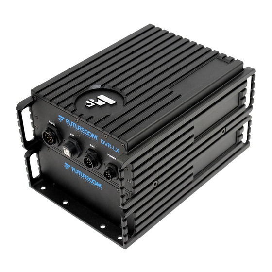
- Page 1 Futurecom Systems Group, ULC ® DVR-LX Installation Guide Document: 8M093X01 Revision: R1.0 Date: 2021-06-01...
- Page 2 NOTES 8M093X01 R1.0...
- Page 3 Manual Revisions Date Notes & References May 2021 Original Release 8M093X01 R1.0...
-
Page 4: Table Of Contents
Instructions ........................ 17 Cable Connections ...................... 19 Cautionary Notes & Considerations ................19 Configuration Terms ....................19 DVR-LX and Duplexer Connections ................20 In-Band Notch Filter Connectors ................21 Power Cable ......................23 Configuration Identification ..................25 Standard Installation Cables ..................26 Installation Drawings .................... - Page 5 Preparation ........................ 38 APPENDIX A- AUXILIARY CABLE ................39 APPENDIX B- CONTROL CABLE ................40 APPENDIX C- CABLES BY TYPE ................41 Appendix D- DVR-LX ANTENNAS ................42 Glossary ........................43 References ........................45 Contact Information ....................46 8M093X01 R1.0...
-
Page 6: Proprietary Statement
Proprietary Statement © 2021 Futurecom Systems Group ULC. All Rights Reserved Futurecom, PDR8000, DVR-LX, the Futurecom Logo and the Stylized FC logo are registered trademarks of Futurecom Systems Group, ULC. All other trademarks are the property of their respective owner. -
Page 7: Declaration Of Conformity
To ensure compliance, operations at closer than this distance is not allowed. Futurecom requires the P25 DVRS operator to ensure FCC/ISED Requirements for Radio Frequency Exposure are met. The minimum distance between all possible personnel and the body of the DVRS equipped vehicle is specified in the RF Safety Booklet . -
Page 8: Déclaration De Conformité
Pour assurer la conformité, le fonctionnement à une distance moins élevée n’est pas autorisé. Futurecom demande à l’opérateur du répéteur P25 DVRS de satisfaire aux exigences de la FCC/ISED en matière d’exposition à l’énergie RF. La distance minimale entre toutes les personnes possibles et une antenne omnidirectionnelle doit respecter les indications de la . -
Page 9: Introduction
System (DVRS). When a Portable Subscriber Unit (PSU) has difficulty reaching a system tower, a DVR- LX can help by linking the PSU to a higher power mobile radio or MSU. The DVR-LX is designed to be seamlessly interfaced to: •... -
Page 10: Installation Planning
Cable connector screws Programming Details This section will detail programming information needed to enable certain installation options. For full instructions on how to program the DVR-LX, please refer to the VR Programming Guide Bypass Switch RF Bypass Switch with non-APX8500 MSU If installing an in-band DVR-LX, it comes equipped with an internal RF bypass switch. - Page 11 DVR-LX is active to ensure interference-free communication. When the DVR-LX is paired with a non-APX8500 MSU, the switch bypasses the filtering at the output of the MSU when a DVR-LX disabled talk group (TG) is selected on the MSU control head.
- Page 12 If installing an in-band DVR-LX, it comes equipped with an internal RF bypass switch. This switch bypasses the filtering at the output of the MSU as required to allow access to the full frequency band when DVR-LX is not enabled or to block certain frequencies when DVR-LX is active to ensure interference-free communication.
-
Page 13: Status Lights
– ‘Primary Light’, ‘VR On Light’, ‘LOC Mode Light’, or ‘SYS Mode Light’. Primary & On Lights The DVR-LX status icon located on the top right corner of the control head can be used to determine when the repeater is on and whether it is acting as a Primary or Secondary device. - Page 14 Figure 5: Primary & On Lights Configuration System & Local Mode Lights The top line of the control head can be used to determine whether the DVR-LX is operating in system (SYS) or local (LOC) mode. Some users may prefer to have a more obvious indication of the DVR-LX status.
-
Page 15: Avra
Figure 7: System and Local Mode Lights Configuration Automated VR Activation (AVRA) The AVRA option enables automated DVR-LX ON/OFF control triggered by an external switch – portable charger, door switch etc. To enable AVRA operation, the following must be configured via FRC in the Hardware... - Page 16 Figure 9: AVRA Auxiliary Configuration 8M093X01 R1.0...
-
Page 17: Mounting Instructions
Motorola. Preparation The flat mount DVR-LX is shipped with a mounting base attached by 4 screws. If a template is needed for installation, the mounting base may be removed and used for that purpose. - Page 18 NOTE: There are holes to accommodate up to 8 mounting points, with only 4 required (See Figure 10: DVR-LX Mounting Screws-Stacked) Step 2: Repeat Step 1 for in-band filters (if applicable) and duplexer (for flat mount configuration). Step 3: Connect all cables according to appropriate configuration.
- Page 19 Figure 11: DVR-LX Mounting Screws- Flat Note: Mounting Base and Repeater must have Futurecom logo at the same end to ensure accessibility of mounting screw holes. 8M093X01 R1.0...
-
Page 20: Cable Connections
Cross-Band: DVR-LX operates in a different frequency band than all of the system frequency bands. Stacked: DVR-LX components are stacked one on top of the other which requires more height for installation. Flat: DVR-LX components are provided individually allowing for a lower profile installation. -
Page 21: Dvr-Lx And Duplexer Connections
DVR-LX and Duplexer Connections The DVR-LX typically sits on top of a duplexer, as shown in Figure 13. Figure 12: Stacked DVR-LX with Duplexer Figure 13 DVR-LX and Duplexer Connectors - Front and Back View The front of the DVR-LX includes connections for: •... -
Page 22: In-Band Notch Filter Connectors
For In-Band DVR-LX configurations, one or two notch filters are also required. Typically, the DVR-LX notch filter sits on top of the MSU notch filter, as shown in Figure 15 and each filter is connected between the DVR-LX/MSU and its antenna. - Page 23 Figure 16: In-Band Notch Filter for 700 MHz Figure 17: Notch Filter Connectors for 700 MHz – Front and Back View The front of the DVR-LX and MSU notch filters have no connection options. The back of the DVR-LX notch filter includes connections for: •...
-
Page 24: Power Cable
3. From the inside of the vehicle, feed the red lead (without lug attached) through the access hole into the engine compartment. 4. Find a grounding point close to the DVR-LX location. Shorten the black lead. 5. Strip the end of the black lead as required. Crimp the large lug on the black lead and connect it to the vehicle chassis ground. - Page 25 Figure 18 - DVR-LX Cross-Band Simplex (Front) To MSU Antenna To DVR Antenna Figure 17 - DVR-LX Cross-Band Simplex (Back) 8M093X01 R1.0...
-
Page 26: Configuration Identification
Configuration Identification Using the table below, identify which configuration of DVR-LX is to be installed and refer to the appropriate configuration drawing for cabling instructions. DVR-LX In-band/Cross-band Stacked/Flat Configuration # Band w System Freq Duplex Stacked In-band Flat 700MHz Stacked... -
Page 27: Standard Installation Cables
RA TNC Male to RA 7W900X04-02 2.5ft NOTE: For Flat Mount Duplex, 2 cables TNC Male provided DVR-LX Ant to In-Band Filtering RF RA Mini UHF Male to 7W083X16-01 Cable RA Mini UHF Male NOTE: For VHF/UHF In-Band 15-Pin Male to 9-Pin... -
Page 28: Installation Drawings
Installation Drawings Configuration 1: Duplex (700 or 800MHz) In-band Stacked Refer to Standard Installation Cables section for mapping of cable diagram numbers to part numbers Figure 19: Configuration 1 - Front View To MSU To DVR Antenna Antenna Figure 20: Configuration 1 - Back View 8M093X01 R1.0... - Page 29 In-Band RF Switch Cabling To use the RF Switch for In-Band DVR-LX units, connect the cables as shown in Figures 17 and 18. To enable the RF Switch operation, refer to the programming instructions for Bypass Switch. Figure 21: DVR-LX AUX - Front View Figure 22: DVR-LX AUX - Back View 8M093X01 R1.0...
-
Page 30: Configuration 2: Duplex (700 Or 800Mhz) In-Band Flat
Configuration 2: Duplex (700 or 800MHz) In-band Flat Refer to Standard Installation Cables section for mapping of cable diagram numbers to part numbers Figure 23: Configuration 2 - Front View To DVR To MSU Antenna Antenna Figure 24: Configuration 2 - Back View 8M093X01 R1.0... -
Page 31: Configuration 3: Duplex (Vhf Or Uhf) In-Band Stacked
Configuration 3: Duplex (VHF or UHF) In-band Stacked Refer to Standard Installation Cables section for mapping of cable diagram numbers to part numbers Figure 25: Configuration 3 - Front View To MSU Antenna To DVR Antenna Figure 26: Configuration 3 - Back View 8M093X01 R1.0... -
Page 32: Configuration 4: Duplex (Vhf Or Uhf) In-Band Flat
Configuration 4: Duplex (VHF or UHF) In-band Flat Refer to Standard Installation Cables section for mapping of cable diagram numbers to part numbers Figure 27: Configuration 4 - Front View To DVR To MSU Antenna Antenna Figure 28: Configuration 4 - Back View 8M093X01 R1.0... -
Page 33: Configuration 5: Duplex Cross-Band Stacked
Configuration 5: Duplex Cross-band Stacked Refer to Standard Installation Cables section for mapping of cable diagram numbers to part numbers Figure 29: Configuration 5 - Front View To MSU To DVR Antenna Antenna Figure 30: Configuration 5 - Back View 8M093X01 R1.0... -
Page 34: Configuration 6: Duplex Cross-Band Flat
Configuration 6: Duplex Cross-band Flat Refer to Standard Installation Cables section for mapping of cable diagram numbers to part numbers Figure 31: Configuration 6 - Front View To MSU To DVR Antenna Antenna Figure 32: Configuration 6 - Back View 8M093X01 R1.0... -
Page 35: Configuration 7: Simplex (Vhf) In-Band Stacked
Configuration 7: Simplex (VHF) In-band Stacked Refer to Standard Installation Cables section for mapping of cable diagram numbers to part numbers Figure 33: Configuration 7 - Front View To DVR To MSU Antenna Antenna Figure 34: Configuration 7 - Back View 8M093X01 R1.0... -
Page 36: Configuration 8: Simplex (Vhf) In-Band Flat
Configuration 8: Simplex (VHF) In-band Flat Refer to Standard Installation Cables section for mapping of cable diagram numbers to part numbers Figure 35: Configuration 8 - Front View To DVR Antenna Antenna Figure 36: Configuration 8 - Back View 8M093X01 R1.0... -
Page 37: Auxiliary Port Options
Bypass Switch Automated VR Activation (AVRA to enable this functionality. To connect additional external logic to the DVR-LX, the DB15 male connector of the RF switch cable (Ref# 7, Part Number 7W083X09-01) can be opened and extra wires added to the corresponding pins as described in... - Page 38 with a DB15 male connector with the required pin out and connect it to the DB15 female connector of the Auxiliary cable. Refer to APPENDIX A for pinout details. Possible applications for the auxiliary port include Status Lights and AVRA. CONNECT TO EXTERNAL LOGIC CABLE...
- Page 39 – ‘Primary Light’, ‘VR On Light’, ‘LOC Mode Light’, or ‘SYS Mode Light’. The DVR-LX then provides control input to an external switch which in turn toggles an external light. The external switch and light are not included with the DVR-LX.
-
Page 40: Antenna Installation
Preparation Any DVRS model requires the use of two or three antennas – one or two connected to the MSU and one connected to the DVR-LX. For a list of approved DVR-LX antennas, please refer to 8M093X01 R1.0... - Page 41 Appendix D - DVR-LX ANTENNAS. The MSU and DVR-LX antennas must be installed in such way as not to cause interference. If an APX8500 installation kit is required to achieve this, please refer to separate installation instructions provided by Futurecom (8J087X51).
-
Page 42: Appendix A- Auxiliary Cable
APPENDIX A- AUXILIARY CABLE DVR-LX Auxiliary Cable (7W083X06-01) Pin # Designation Note SWITCH 1 Alternative AVRA Input, operating programmed in the Futurecom Repeater Configurator’s Hardware Setup Screen RXD2 RS232 Input TXD2 RS232 Output RELAY 2 Primary Light Output / as programmed... -
Page 43: Appendix B- Control Cable
APPENDIX B - CONTROL CABLE DVR-LX to MSU Control Cable (7W083X05-01) TO DVR-LX TO APX RADIO 8M093X01 R1.0... -
Page 44: Appendix C- Cables By Type
7W900X94-02 DDN2719A Models with Filtering Cable (91.44cm) RA Mini UHF APX8500 RA Mini UHF VHF & UHF 36” DVR-LX Ant to In- Male to RA 7W083X16-01 DDN9033 In-Band band Filtering Cable (91.44cm) Mini UHF Models Male Control and Power Cables... -
Page 45: Appendix D- Dvr-Lx Antennas
Appendix D - DVR-LX ANTENNAS Freq. Band Gain Order Code Type [MHz] HAD4006A 136-144 Roof / Trunk Mount 0 (Unity) HAD4007A 144-150.8 Roof / Trunk Mount 0 (Unity) HAD4008A 150.8-162 Roof / Trunk Mount 0 (Unity) HAD4009A 162-174 Roof / Trunk Mount... -
Page 46: Glossary
Automated VR Activation. DVR-LX option which permits automated activation of the AVRA DVR-LX by either using a VIP input on the MSU CH / DEK or a pin on the DVR-LX Auxiliary cable. Requires external logic / switch (not provided). - Page 47 Keyword Description DVR-LX components are stacked one on top of the other Stacked which requires more height for installation. System Mode: DVR-LX mode which enables repeated communication between the local PSUs, MSU and two-way communication with Dispatcher and System PSUs.
-
Page 48: References
DVR-LX/DVR/VRX1000 > Installation & Programming Guide > VR Programming Guide 3. RF Safety Booklet/ la Brochure Sécurité RF (Canada): DVR-LX/DVR/VRX1000 > RF Safety Booklet > RF Safety Booklet – APX – DVRS - Canada 4. RF Safety Booklet/ la Brochure Sécurité RF (USA/États-Unis): DVR-LX/DVR/VRX1000 >... -
Page 49: Contact Information
Subscribe to our newsletter if you want to be informed about new releases and updates. Please visit http://futurecom.com/support/newsletter/ Futurecom Systems Group, ULC. 3277 Langstaff Rd Concord, Ontario L4K 5P8 Canada 1-800-701-9180 https://www.futurecom.com/ © 2021 Futurecom Systems Group, ULC 8M093X01 R1.0...
Need help?
Do you have a question about the DVR-LX and is the answer not in the manual?
Questions and answers