
Related Manuals for Profound Sonalleve MR-HIFU

Summary of Contents for Profound Sonalleve MR-HIFU
- Page 1 Sonalleve MR-HIFU Instructions for Use - Desmoid Application English / Release 3.7...
- Page 2 © Profound Medical Inc., 2020. All rights reserved. No part of this document may be reproduced or transmitted in any form or by any means, electronic, mechanical, photocopying, recording, or otherwise, without prior written permission from Profound Medical Inc.
-
Page 3: Table Of Contents
1.1. About Sonalleve MR-HIFU ........ - Page 4 5.3. Exiting Therapy ..........5.4. Exiting the Sonalleve MR-HIFU application ..... .
- Page 5 7.1.2. User Routine Checks Program ..... . 7.2. Sonalleve MR-HIFU Quality Assurance (QA) procedure ...
- Page 6 10.11. Legal notices ......... . . 10.11.1. Profound REACH statements .....
-
Page 7: Introduction To Sonalleve Mr-Hifu
Achieva 1.5 T/3.0 T or Ingenia 1.5 T/3.0 T MR scanner. Sonalleve MR-HIFU system. This manual will guide you in the use of the Sonalleve MR-HIFU system. In addition, all the instructions and safety precautions for the MR scanner apply when working with the Sonalleve MR- HIFU system. -
Page 8: Notations
Apart from this manual, Profound Medical also produces a Technical Description (in English only). It provides additional data essential for safe operation and the measures or conditions necessary for installing the Sonalleve MR-HIFU system for use with the MR scanner. -
Page 9: Intended Use
Magnetic field 1.3. Intended use This Profound Medical product is intended to be installed, used and operated only in accordance with the safety procedures and operating instructions given in this Instructions for Use for the purpose for which it was designed. The purpose for which the product is intended is given below. -
Page 10: Sonalleve Desmoid Application
This list of adverse effects and the estimates on their frequency of occurrence are based on reports in literature. References to the relevant literature will be supplied on request by your local Profound Medical application support representative. -
Page 11: Operator Profile
The other products and components that may be used with the system may each have their own Instructions for Use. Changes and/or additions to the product should only be carried out by Profound Medical or by third parties expressly authorized by Profound Medical to do so. Such changes and/or additions must comply with all applicable laws and regulations that have the force of law within the jurisdiction(s) concerned, and with best engineering practice. -
Page 12: Compliance
If you require further information about training in the use of this product, please contact your local Profound Medical representative. 1.8. Installation instructions The installation instructions for the Sonalleve MR-HIFU system are supplied by Profound Medical in separate documentation. The installation must only be performed by appropriately trained personnel. Profound Medical can... -
Page 13: System Classification
1. Introduction to Sonalleve MR-HIFU > 1.9. System classification 1.9. System classification According to the classification in the international/European standard IEC/EN 60601-1: Tab. 2: Equipment classification. EQUIPMENT CLASSIFICATION Classification according to IEC 60601-1, Medical electrical equipment Protection against electrical shock System: Class 1 Medical Electrical Equipment. -
Page 14: Safety
MR-HIFU equipment. Failure to follow appropriate safety measures may lead to injuries to the patient or personnel, or damage to the equipment. Make sure that all of the electrical and mechanical assemblies and parts of the Sonalleve MR-HIFU system are used with care and routinely inspected according to the instructions in this manual. - Page 15 There is a Configuration Editor included in the HIFU Service tools that is intended for qualified service personnel only, changing configurations may compromise patient safety and cause problems in the operation and performance of the Sonalleve MR-HIFU system. Never change the configurations without first consulting the Profound Medical Service organization.
-
Page 16: Contraindications And Restrictions
Ultrasound protection. Do not sonicate a positioning pad on purpose. 2.2. Contraindications and restrictions This Profound Medical product should not be used if any of the following contraindications exist or are thought to exist: MR contraindications specified in the MR scanner's Instructions for Use. -
Page 17: Heat And Specific Absorption Rate (Sar)
2.3.1. Specific Absorption Rate (SAR) Both the MR system and the Sonalleve MR-HIFU system produce thermal energy, which is absorbed by the patient during treatment. The International/European standard IEC/EN 60601-2-33... -
Page 18: Specific Energy Dose (Sed)
4.5.4. Cooling time for more information on cooling time. The Sonalleve MR-HIFU systems include an active Direct Skin Cooling (DISC) device. The purpose of the device is to facilitate faster tissue cooling by keeping the patient interface at a constant temperature throughout the treatment. -
Page 19: Clothing And Environmental Conditions
2. Safety > 2.4. Contrast agents and medication 2.3.5. Clothing and environmental conditions Refer to the MR scanner’s Instructions for Use. WARNING The whole body SAR limits are only valid for room temperatures not greater than 24 °C (75.2 °F) and relative humidity not greater than 60%. 2.4. -
Page 20: Emergency Stop And Safety Devices
During pre-treatment scanning, and when sonication is not on, the PESB functions like the MR nurse call button: it gives an audio signal but does not stop scanning. WARNING Do not use the standard MR Nurse Call button with the Sonalleve MR-HIFU system. Use the Patient Emergency Stop Button (PESB) instead. Instructions for Use... -
Page 21: Safety Device (Sd)
2. Safety > 2.5. Emergency Stop and Safety Devices NOTICE Instruct the patient on how and when to use the patient emergency stop button (PESB). Such situations include: Sudden pain during the procedure. Skin heating. Numbness in legs or other body parts. Nausea. -
Page 22: Software Abort Sonication Button
2.8. Mechanical and electrical safety Before using the Sonalleve MR-HIFU hardware components, visually check them to ensure that they are undamaged. Especially, inspect all the wires, hoses, connectors and sockets. Patient or operator injury could occur if these instructions are not properly followed. -
Page 23: Protecting The Equipment Against Liquids
Use disposable sheets to absorb any spilled liquid. Do not allow liquids to enter any other part of the Sonalleve MR-HIFU equipment. Before each treatment, visually check that the Sonalleve Table Top is not leaking. -
Page 24: Chemical Safety
2. Safety > 2.10. Chemical safety 2.10. Chemical safety The ultrasound transducer inside the Sonalleve Table Top is immersed in liquid. The liquid inside the Table Top is in a sealed container and does not come in contact with operators or patients in normal operation of the system. -
Page 25: Battery Safety
In addition, the customer must have a comprehensive security strategy addressing external and internal threats. For more information, refer to the Technical Description. For safety reasons, the Sonalleve MR-HIFU system is isolated from the hospital network during the Therapy stage. - Page 26 To ensure the safe operation of the system and the confidentiality of patient data, operators working with the Sonalleve console must observe the following rules: CAUTION To protect your Sonalleve MR-HIFU system against viruses, malware and unauthorized access: Never use the Sonalleve console for browsing intranets or the Internet.
-
Page 27: Malware Detection
Windows operating system and to the anti-virus software. The security updates are validated by Profound Medical and must be controlled for this product. The updates are distributed by the Profound Medical service organization. Remote installation of security updates is not supported because it could involve risk to patient safety. -
Page 28: Symbols And Labels On The Equipment
Symbols that appear on Sonalleve MR-HIFU equipment are listed in the following table. Refer to the MR scanner’s Instructions for Use for a complete list of symbols on the MR system. The system label of the Sonalleve MR-HIFU system is located on the side of the Sonalleve Table Top. - Page 29 2. Safety > 2.18. Symbols and labels on the equipment On the frame The movement of the trolley is locked when the marked beside the brake end of the brake pedal is pressed. pedal of the trolley On the frame The movement of the trolley is released when the brake beside the brake pedal is in the middle position.
- Page 30 2. Safety > 2.18. Symbols and labels on the equipment Product labels Indicates that the medical device or other item is only for use with a 1.5 T MR scanner. Product labels Indicates that the medical device or other item is only for use with a 3 T MR scanner.
- Page 31 2. Safety > 2.18. Symbols and labels on the equipment Indicates the manufacturer's serial number for the specific System label medical device. QA phantom Planning console Patient Table Generator Cabinet label on the roof of the cabinet DISCFILL tool Filter Panel Patient trolley Indicates the production batch code or lot number of the Packages of...
- Page 32 2. Safety > 2.18. Symbols and labels on the equipment System package Fragile, handle with care labels Indicates a medical device that can be broken or damaged if not handled carefully. System package Keep dry labels Indicates a medical device that needs to be protected from moisture.
- Page 33 2. Safety > 2.18. Symbols and labels on the equipment The manufacturer of the item declares that the item Packages of conforms to the applicable European Union directives. gel pads Packages of QuickCover Ultrasound Protective Covers System label The manufacturer of the medical device declares that the medical device conforms to the European Medical Device Directive 93/42 EEC.
-
Page 34: System Overview
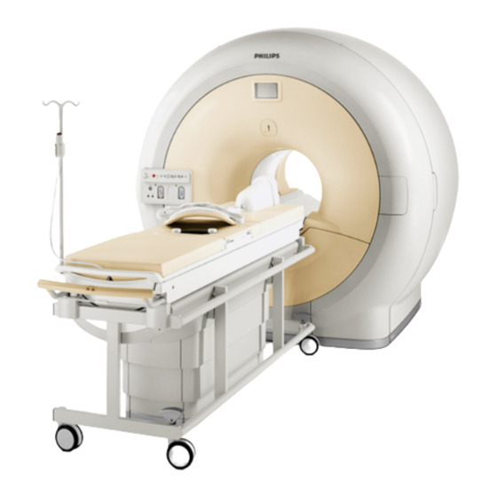
3. System overview > 3.1. Main system components 3. System overview The Sonalleve MR-HIFU system is designed to be used with Philips MR scanners (see 1.1. About Sonalleve MR-HIFU). The Sonalleve Table Top can be easily removed to enable normal, diagnostic use of the MR scanner. - Page 35 Cables for the Sonalleve MR-HIFU system enter the examination room through a dedicated HIFU Filter Panel on the examination room wall. When the Sonalleve MR-HIFU system is not in use, the cables are disconnected and stored in the accessory cart, if available.
- Page 36 Water circulation stops when remote control ends. Water circulates during sonications but may be automatically switched off when scanning other protocols. The Sonalleve MR-HIFU systems are delivered with the DISC installed. The DISC can also be installed as an upgrade.
- Page 37 3. System overview > 3.1. Main system components Fig. 5: When DISC is pre-installed at the factory, the hose connectors are located in the Table Top connector panel. Fig. 6: When DISC is installed as an upgrade, the hose connectors are located in the accessory box at the front end of the Table Top.
- Page 38 3. System overview > 3.1. Main system components Brake pedal Fig. 7: The brake pedal of the trolley of the Sonalleve Table Top. The symbols on the frame of the trolley beside the brake pedal indicate the brake function as follows: Tab.
- Page 39 3. System overview > 3.1. Main system components SWIVEL RIGHT side of brake pedal pressed All the five wheels are free (brakes off) The direction of the center wheel is locked, which makes it easier to turn the trolley Table Top release To release the Table Top when pushing the Table Top into the magnet and when pulling the Table Top back out, lift either of the two Table Top release handles located on both sides of the Table Top (see the figure below).
-
Page 40: Sonalleve Console
The Sonalleve MR-HIFU system requires a separate cabinet for power distribution and the electronics. The Sonalleve Generator Cabinet is located in the technical room. The main power switch for the Sonalleve MR-HIFU system is located in the power distribution unit (PDU) in the Sonalleve Generator Cabinet. -
Page 41: Acoustic Contact Liquid
Ultrasound Window Cover. NOTICE The vacuum cushion provided with the Sonalleve MR-HIFU system is only intended for use in MR- HIFU, not in diagnostic clinical imaging. To order additional consumables (such as gel pads) or replacements for accessories that are provided with the Sonalleve MR-HIFU system, contact your local Profound Medical representative. -
Page 42: Other Accessories
SPT (System Performance Testing) phantom holder. DISCfill tool NOTICE The SPT phantom is a part of the MR system and not provided with the Sonalleve MR-HIFU system. If you need replacements for accessories, contact your local Profound Medical representative. Instructions for Use... -
Page 43: The Discfill Tool
There is also a draining hose, with one end open. Fig. 12: DISCfill (1), The filling hose (2), The draining hose (3) 3.4. Technical specifications Tab. 5: Key treatment-related technical specifications for the Sonalleve MR-HIFU system. Feature Specification Temperature measurement update 3.5 seconds or less... -
Page 44: Ultrasound Field Distributions
3. System overview > 3.4. Technical specifications 3.4.1. Ultrasound field distributions The ultrasound field distribution was characterised by performing hydrophone measurements with a Sonalleve system at the nominal focus with 20W acoustic power. Hydrophone needle was moved in order to measure pressures in both coronal and axial planes. Y-axis is parallel to the beam axis. Typical values for the dimensions of the focal spot are shown in the table below. - Page 45 3. System overview > 3.4. Technical specifications Fig. 14: Typical temporal-average intensities ITA (x=0, y, z=0) at 1.0 MHz Fig. 15: Typical temporal-average intensities ITA (x=0, y, z=0) at 1.2 MHz Instructions for Use 43 (192) 109745C2 / 02-2022...
- Page 46 3. System overview > 3.4. Technical specifications Fig. 16: Typical temporal-average intensities ITA (x=0, y, z=0) at 1.44 MHz Instructions for Use 44 (192) 109745C2 / 02-2022...
-
Page 47: Treatment Methods
4. Treatment methods > 4.1. Basic concepts 4. Treatment methods This chapter explains the terms and concepts necessary for understanding the Sonalleve MR-HIFU treatment workflow. 4.1. Basic concepts In High Intensity Focused Ultrasound (HIFU) treatment, an ultrasound beam is focused on a small volume within the target tissue. - Page 48 4. Treatment methods > 4.1. Basic concepts Beam Shaping A Sonalleve software feature that allows the user to selectively limit the maximum acoustic intensity in a part of the transducer beam that goes through a sensitive organ. Cavitation Interaction between ultrasound and microbubbles in water or within tissue, which may affect the treatment outcome at high ultrasound power densities.
- Page 49 Treatment The whole procedure involving the patient care and the use of the Sonalleve MR-HIFU System for therapy and pre and post-therapy activities. Within the context of the Sonalleve console: The entire process required to treat the patient including the planning, preparation, therapy and reporting stages.
-
Page 50: Patient Selection
4. Treatment methods > 4.2. Patient selection Treatment cell Lines displayed around a treatment cell to visualize its advised minimum safety margin distance from sensitive tissues. Treatment The plane on which the treatment cells in a cluster are located. The center of plane each treatment cell is in this plane. -
Page 51: Electronic Deflection
4. Treatment methods > 4.4. Electronic deflection 4.4. Electronic deflection The Sonalleve MR-HIFU system is able to steer electronically the position of the treatment point within a limited range around the natural focus of the transducer. This method is called electronic deflection. -
Page 52: Thermal Dose And Temperature Monitoring
If a treatment cell cluster is selected, the cumulative thermal dose is displayed for that cluster. The Sonalleve MR-HIFU system records temperature in all the imaging planes. The system automatically positions some stacks at the location of the expected maximum heating. Some stacks are freely adjustable by the user, to be placed in locations where heating is not expected to occur. - Page 53 4. Treatment methods > 4.5. Temperature monitoring Fig. 18: Example of a temperature map. If the temperature increases significantly at regions other than the intended heating volume (plus margin), the system issues warnings. The warnings may be caused by movement or other artifacts and their reason and safety consequences should be understood before continuing with the treatment.
-
Page 54: Monitoring Near-Field Heating
4. Treatment methods > 4.5. Temperature monitoring The Sonalleve Software calculates the thermal dose from temperature maps. As the volume outside the intended heating location is not expected to warm up, thermal dose is not calculated there. Therefore, any potential temperature artefacts outside the intended heating location will not produce any graphical depiction of dose. -
Page 55: Cooling Time
4. Treatment methods > 4.5. Temperature monitoring Fig. 19: If the sonication is estimated to induce heat close to the risk level, the software displays one of the above warnings (depending on risk level), and the user is asked to confirm the start of the sonication. NOTICE Variations in the patient’s anatomy and physiology, environmental conditions, etc., affect the heating and cooling of the tissue. -
Page 56: Temperature Limits
4.5.5. Temperature limits The Sonalleve MR-HIFU system imposes the following temperature limits to prevent overheating of tissue: Warning zone heating limit: 47 °C (116.6 °F). If the system detects this temperature inside the... -
Page 57: Misplaced Heating Or Motion Artefact
4. Treatment methods > 4.6. Motion detection 4.6.1. Misplaced heating or motion artefact? If the temperature increases significantly outside the intended heating volume, the system issues warnings. The warnings may be caused by movement or other artifacts and their reason and safety consequences should be understood before continuing with the treatment. -
Page 58: User Interface
5. User interface 5.1. Overview The Sonalleve MR-HIFU user interface is used for planning, performing and monitoring the treatment using images obtained from the MR scanner. The user interface provides versatile tools for viewing the images in all imaging planes. The way in which the images are viewed can be optimized for each treatment stage. - Page 59 5. User interface > 5.2. Starting the Sonalleve MR-HIFU application Fig. 23: Application start shortcuts. Left: desktop shortcut. Right: Start menu shortcuts. To change between the Therapy and Research modes, restart the application. Site Default Configuration The Site Default Configuration is the configuration that is always taken into use when the Sonalleve Application is started from the Sonalleve Therapy shortcut.
-
Page 60: Selecting Between The Therapy And Standalone Mode
5. User interface > 5.2. Starting the Sonalleve MR-HIFU application 5.2.2. Selecting between the Therapy and Standalone mode To select between Therapy mode and Standalone mode, select the mode in the Mode list in the start page of the Sonalleve MR-HIFU application: Fig. -
Page 61: Exiting Therapy
Standalone mode, click Standalone. 5.3. Exiting Therapy To exit Therapy mode and return to the start page of the Sonalleve MR-HIFU application, either click the Therapy application button or select End Therapy in the File menu. Fig. 28: File menu during Therapy. -
Page 62: Exiting The Sonalleve Mr-Hifu Application
For more information on saving therapy data, see 5.11. Saving and recovering your work. 5.4. Exiting the Sonalleve MR-HIFU application To close the Sonalleve MR-HIFU application, select Exit in the File menu. Instructions for Use 60 (192) -
Page 63: Therapy Application Screen Layout
5. User interface > 5.5. Therapy application screen layout 5.5. Therapy application screen layout The Sonalleve MR-HIFU Therapy application screen is divided into three main areas: Therapy Wizard (1), Image Area (2) and Hardware Status Area (3). Fig. 31: Sonalleve MR-HIFU Therapy application screen layout. - Page 64 5. User interface > 5.6. Therapy Wizard Treatment Cell Planning Hardware Initialization Therapy Complete all mandatory actions in each stage. Otherwise, you cannot move on to the next stage. However, you can always return to a previous stage using the appropriate navigation buttons. The visual appearance of each navigation button indicates if you can move to that stage: Blue color indicates Strong orange color indicates a...
-
Page 65: Viewing Images
5. User interface > 5.7. Viewing images 5.7. Viewing images The Image Area shows the planning and monitoring images produced by the MR console in four separate windows. The protocol name and the date and time of the image, as well as the currently displayed image plane are shown on the upper edge of each window. -
Page 66: Basic Viewing Tools
5. User interface > 5.7. Viewing images 5.7.1. Basic viewing tools Tab. 9: Basic viewing tools. Button Tool Function/Use Zoom Used for Zooming in/out on an image. Can also be activated by mouse right + left/scroll buttons. Right clicking the button gives you an option to cancel any modifications. -
Page 67: Advanced Viewing Tools
5. User interface > 5.7. Viewing images 5.7.2. Advanced viewing tools It is often necessary to view the images differently in different stages of the treatment. The advanced viewing tools allow you to change the way in which the images are displayed in the image area. -
Page 68: Overlay Tools
5. User interface > 5.7. Viewing images 5.7.3. Overlay tools The overlay tools assist you during the planning and monitoring of the treatment. They allow the display of objects related to treatment planning and monitoring, such as cells, transducer positions, or temperature maps on top of a planning image. - Page 69 5. User interface > 5.7. Viewing images Fig. 33: Treatment cell visibility drop-down menu. The tool buttons of the following overlays are hidden by default. To add these tool buttons to the toolbar, select them in the Tools → Toolbar Options menu. Tab.
- Page 70 5. User interface > 5.7. Viewing images Transducer beam overlay The transducer beam overlay displays the estimated shape of the transducer beam. The shape of the near field close to the transducer is calculated in real time. This calculation is an approximation that takes into account OARs, the distribution of transducer elements at the surface of the transducer, and the position and angulation of the transducer.
- Page 71 5. User interface > 5.7. Viewing images +10 mm +20 mm The transducer beam overlay visualizes the treatment cell safety margin and the far-field safety margin: Fig. 35: The transducer beam overlay visualizes the treatment cell safety margin (1) and the far-field safety margin (2). Instructions for Use 69 (192) 109745C2 / 02-2022...
- Page 72 5. User interface > 5.7. Viewing images Treatment cell visualization The status of each treatment cell is indicated with different colors and markings. Tab. 16: Treatment cell color codes and markings. Cell Cell state appearance A pristine, correctly positioned cell. Not marked checked with the Toggle Cell Checked tool.
-
Page 73: Adding, Selecting And Removing Objects
5. User interface > 5.8. Adding, selecting and removing objects Fig. 36: Treatment cells. 5.8. Adding, selecting and removing objects With this group of tools you can add, select and remove objects. The buttons are active only in those stages in which they can be used. Button Tool Function/Use Adds an object (PTV, treatment cell, marker, freehand ROI, freehand... -
Page 74: Controlling And Monitoring The Sonication
5. User interface > 5.9. Controlling and monitoring the sonication Remove Removes the selected object. Current Toggle Marks the selected treatment cell as safety checked, or removes the Cell mark. Checked The cells that are marked safety checked are shown in green (see 5.7.3.2. -
Page 75: System Status Display
5. User interface > 5.9. Controlling and monitoring the sonication 5.9.1. System Status Display The System Status Display shows the modes of the Sonalleve MR-HIFU system. The display includes the following icons: Tab. 18: The System Status Display icons. Icon Meaning Scanner status (scanning/inactive). - Page 76 5. User interface > 5.9. Controlling and monitoring the sonication Tab. 20: Overlays on the System Status Display icons. Overlaid symbol Example Meaning Rotating gears over a The system is making preparations: for example, yellow icon installing embedded software or changing the MR scan protocol.
- Page 77 5. User interface > 5.9. Controlling and monitoring the sonication Fig. 38: The Fat Monitoring dialog shows the position of the T2 fat monitoring scan with respect to tissue boundaries. It also provides more information on why the fat monitoring data could not be used. The image can be windowed using the standard tools.
-
Page 78: Sonication Buttons
5. User interface > 5.9. Controlling and monitoring the sonication 5.9.2. Sonication buttons Start Sonication Abort Sonication The Start Sonication and Abort Sonication buttons are used for starting and aborting sonication. The buttons are active only in those stages where sonication is possible, i.e. during test sonication and therapy. -
Page 79: Temperature And Thermal Dose
5. User interface > 5.9. Controlling and monitoring the sonication 5.9.3. Temperature and thermal dose When pressing the Start Sonication button, the Sonalleve application scans a few reference images before starting the actual sonication. As the sonication starts, the calculated temperature and thermal dose are shown as overlays. -
Page 80: Temperature Curve
5. User interface > 5.9. Controlling and monitoring the sonication Fig. 41: Cumulative dose contour of a treatment cell cluster. WARNING Always rely on the original dose map when making decisions about the treatment completeness. The cumulative dose map may differ from the original dose map. 5.9.4. - Page 81 5. User interface > 5.9. Controlling and monitoring the sonication Fig. 42: Temperature curve. Additionally, you can also choose to display the temperature and thermal dose along a line that you draw using the Profile Line tool. The tool button is hidden by default, but you can add it to the toolbar from the Tools →...
-
Page 82: Message Area
5. User interface > 5.10. Reporting and logging 5.9.5. Message area The message area in the middle of the Hardware Status Area shows the warnings and error messages of the system. Fig. 44: Message area. Double-clicking a message opens a notification window with more details on the message and instructions on how to clear it. -
Page 83: Viewing And Exporting Logs
5. User interface > 5.10. Reporting and logging Fig. 45: Snapshot Comment dialog. 5.10.3. Viewing and exporting logs The Tools menu contains the Log Viewer, through which you can: View system events. Filter the log to display events according to their: Severity level (unknown, Debug, Info, Warning, Error). -
Page 84: Saving And Recovering Your Work
5. User interface > 5.11. Saving and recovering your work Fig. 47: Storing logs in an archive 5.11. Saving and recovering your work To save your work, you should: Create a Clinical Summary Report as described in 5.10.1. Generating reports. Create a Saved State file. - Page 85 Ensuring sufficient free disk space Each Saved State in the database consumes disk space on the workstation. For unhindered operation of the Sonalleve MR-HIFU application and the Sonalleve console in general, sufficient disk space must always be available. The Sonalleve MR-HIFU application monitors the amount of available disk space. When the available disk space is getting too low, the following warning appears in the start page of the application.
- Page 86 5. User interface > 5.11. Saving and recovering your work In the Session Manager dialog, you can view the contents of the internal database and import, export and delete Saved States. Select Manage States in File menu to open the Session Manager.
-
Page 87: Language Settings
Click Export. Select the directory and file name to save to. The system can also export directly to a CD/DVD. For instructions on burning Saved States to a DVD, see 10.5. Copying Sonalleve MR-HIFU treatment data to DVD. If a Saved State file is needed without identifying personal data, use the Export De-identified tool instead of Export. -
Page 88: Keyboard Shortcuts
5. User interface > 5.13. Keyboard shortcuts 5.13. Keyboard shortcuts The following keyboard shortcuts are active when you have clicked on the Image Area to select it for viewing. The tools available may vary between the treatment stages and tab pages within a stage. -
Page 89: Workflow
Always refer to the Application Guide for application-specific details. 6.2. Preparing the equipment The Sonalleve MR-HIFU system is typically only used periodically, alternating with normal MR scanning. One person can switch between the standard tabletop and the Sonalleve Table Top in 5 to 10 minutes. - Page 90 6. Workflow > 6.2. Preparing the equipment CAUTION The patient support must remain at the lowest position. Do not raise the support height after the Sonalleve Table Top is placed in position. Bring in the Sonalleve Table Top . Position the trolley over the top of the lifting unit until the lateral stops are correctly inline with the buffer blocks on the patient support.
- Page 91 6. Workflow > 6.2. Preparing the equipment Fig. 53: Table Top connector panel. Unhook the Sonalleve Coil Cables from their holders on the Table Top and connect them to their sockets. Remove the ultrasound window cover from the top of the ultrasound window. The ultrasound window cover is used for protecting the membrane on top of the ultrasound window when the Table Top is not in use.
-
Page 92: Preparing The Table Top For The Patient
NOTICE Before preparing the Table Top for the patient, check that the Quality Assurance (QA) procedure has been carried out. For more information on QA, see 7.2. Sonalleve MR-HIFU Quality Assurance (QA) procedure. Preparing the Table Top for use with a gel pad To prepare the Sonalleve Table Top for the treatment session, when using a gel pad: Open a gel pad package and visually check that the gel pad is not damaged. -
Page 93: Preparing The Patient
Place the appropriate mattresses, such as the footrest and other pads on the Table Top. If your Sonalleve MR-HIFU system is equipped with DISC that has been installed as an upgrade, always use a mattress so that there is no skin contact to DISC connectors and hoses. -
Page 94: Positioning The Patient On The Table
Make sure that the patient's limbs are within the edges of the Table Top so that they are not pinched. Instruct the patient to lie still when being transported on the Sonalleve MR-HIFU Table Top. Pay particular attention to thresholds. -
Page 95: Verifying The Patient Positioning
6. Workflow > 6.3. Preparing the patient WARNING Never leave the coil cable in contact with the skin, as localized RF heating may cause skin burns. Use pads between the skin and the coil cable. Give the patient the PESB and instruct them how to use it. See 2.5.1. Patient Emergency Stop Button (PESB). - Page 96 6. Workflow > 6.3. Preparing the patient Fig. 58: ExamCard Push setting. Fig. 59: Therapy ExamCard. Scan Survey. Activate the Offset scan. Open the Offsets page (offc/ang). Fig. 60: The Offsets page. Position the center of the slice to the center of the treatment area. Fig.
- Page 97 6. Workflow > 6.3. Preparing the patient Check the offsets to see how much the patient needs to be moved in each direction: Direction + / - Move the patient Right Left Into the scanner Out of the scanner Fig. 62: An example of offsets. To move the patient according to the measurements: Release the Table Top and pull it out of the magnet bore.
-
Page 98: Scanning The Planning Images
6. Workflow > 6.4. Scanning the planning images Fig. 64: An artefact caused by a surgical clip (1), an air bubble (2) and a skin fold (3). If needed, pull the Table Top out and reposition the patient. Push the Table Top back in and scan the survey and bubble/scar verification scans again. - Page 99 6. Workflow > 6.5. Preparing the monitor scan WARNING Always use the pre-determined and tested temperature measurement ExamCards and protocols for temperature mapping. The use of other protocols may lead to unexpected image quality or inefficient temperature detection, which may then lead to overheating of tissue, insufficient treatment, unintended heating locations and tissue damage.
- Page 100 6. Workflow > 6.5. Preparing the monitor scan Fig. 65: Push to Workstation must be active to ensure that the images are transferred to the Sonalleve console. Left: In MR software R5 the setting is in Advanced Properties, accessible through the right-click drop-down menu. Right: The setting in MR software R3 and R4.
- Page 101 6. Workflow > 6.5. Preparing the monitor scan Fig. 67: An example of positioning the monitor slices . NOTICE For more details, refer to the Application Guide. Check that CLEAR=yes. This enables temperature map calculation. Select the fat-monitoring protocol. Position the center of the slice stack over the subcutaneous fat layer in coronal plane. Do not angulate.
- Page 102 6. Workflow > 6.5. Preparing the monitor scan Fig. 68: An example of positioning the fat-monitor slices. Start the temperature mapping scan. The scanner is now under remote control. WARNING Always enable the remote control mode of the MR console as early as possible to allow a minimum of 5 minutes of water circulation in DISC system before the first therapy sonication.
-
Page 103: Therapy Planning
6.6. Therapy planning 6.6.1. Starting Therapy in the Sonalleve MR-HIFU application Fig. 70: Starting Therapy. In the start page of the Sonalleve MR-HIFU application, select the appropriate clinical application in the Application list. Select Therapy in the Mode list. Click the Therapy application selection button. -
Page 104: Retrieving The Image Sets
6. Workflow > 6.6. Therapy planning WARNING Incorrect body temperature may affect the success of the treatment. Always use the actual body temperature as a reference value. WARNING Always set the gel pad thickness in Sonalleve user interface to match the actual gel pad thickness that is used in the treatment. -
Page 105: Defining The Planning Target Volume
6. Workflow > 6.6. Therapy planning Fig. 72: Image set retrieval window. To display recently exported image sets, click Query. The images are filtered according to the patient ID, i.e. only the images of the patient that is currently being treated are retrieved. Double-click an image set or select multiple image sets, and click Retrieve. -
Page 106: Defining The Tissue Boundary
6. Workflow > 6.6. Therapy planning Define the Planning Target Volume (PTV) by drawing it on the planning images. Fig. 73: Planning Target Volume delineation. Add PTV by clicking the Add button. Draw the Planning Target Volume on top of the images. If you are using several PTVs, you can give them descriptive names. - Page 107 6. Workflow > 6.6. Therapy planning Start editing the tissue boundaries by selecting one of the lines. Move the tissue boundaries by moving the lines or handles. If needed, add or remove handles by double-clicking the line. To return the tissue boundary lines to the default position, click Reset. Check that there is enough water in the DISC.
- Page 108 6. Workflow > 6.6. Therapy planning Fig. 76: Slice navigation view Center the view to all PTVs to check all boundaries. Confirm the boundaries by accepting. WARNING Make sure to scroll through all images to find any non-uniformities in the tissues. Instructions for Use 106 (192) 109745C2 / 02-2022...
-
Page 109: Positioning The Treatment Volume
6. Workflow > 6.6. Therapy planning 6.6.6. Positioning the treatment volume WARNING Positioning: Always leave sufficient safety margins to sensitive organs or other sensitive structures when drawing Planning Target Volumes or cells. Avoid placing treatment cells any closer to the spine or other sensitive structures than indicated by the far-field safety margin. - Page 110 6. Workflow > 6.6. Therapy planning Do not expose the tip of the Foley catheter to ultrasound, if the tip is touching the bladder wall. Such exposure could lead to local heating, irritation, pain, hematuria, or damage of the bladder wall.
- Page 111 6. Workflow > 6.6. Therapy planning Fig. 78: Treatment cell selection. Check the beam of each of the cells. The beam must not travel through air or sensitive structures, and there must not be unprotected scars in the ultrasound beam path. Verify that safety margins are observed.
-
Page 112: Beam Shaping
6. Workflow > 6.6. Therapy planning 5. You can move the treatment cluster with cells with the Move Treatment Cell Cluster button. For hints and tips on placing the cells optimally, see the Application Guide. If the cell you have placed is not treatable with the current transducer position, it will be marked with a cross and the system issues a warning message. - Page 113 6. Workflow > 6.6. Therapy planning The following figure shows how an OAR ROI is drawn to prevent heating of a scar. Fig. 81: An OAR ROI drawn to prevent heating of a scar. Reduction of the ultrasound intensity is achieved by disabling some of those transducer elements that contribute to the ultrasound field in the OAR region.
- Page 114 6. Workflow > 6.6. Therapy planning Fig. 82: The visualization of the beam path and the ATA affected by an OAR. Only use beam shaping in the near-field side of the transducer beam. OARs should be drawn in the coronal plane. After drawing OARs, always check the resulting shape of the transducer beam visually in a sagittal or transverse slice set.
-
Page 115: Preparing The System For Sonication
6. Workflow > 6.7. Preparing the system for sonication Fig. 83: The correct use of QuickCover. WARNING QuickCover only provides protection for the superficial tissue layer immediately behind the cover strip. Using protective cover strips side-by-side may lead to distorted heating due to the large area of blocked ultrasound beam. -
Page 116: Scanning Temperature Mapping
6. Workflow > 6.7. Preparing the system for sonication Fig. 84: Hardware initialization. WARNING If the system detects a transducer movement failure, it stops the treatment and issues an error message. You must rerun the Hardware Initialization. 6.7.2. Scanning Temperature Mapping Scan the temperature mapping protocol: To see the image quality and any possible artefacts. -
Page 117: Test Sonication
6. Workflow > 6.7. Preparing the system for sonication Fig. 85: The Scan tab. 6.7.3. Test sonication WARNING If the couch has been unlocked for any reason, always perform a test sonication once the Table Top has been pushed back to the treatment position. It is recommended to repeat test sonication always when the Table Top lock or the trolley brake lock is re-engaged after being released. - Page 118 6. Workflow > 6.7. Preparing the system for sonication Select a cluster and a treatment cell. No matter which size and type of cell you choose, the test sonication treats it as a regular 4 mm cell. Select Test Sonication. Using the Power slider, select a power level that is low enough to not cause thermal dose in the tissue.
- Page 119 6. Workflow > 6.7. Preparing the system for sonication Fig. 90: Accepting the offset correction. If the offset exceeds 5 mm (over 2 pixels) in any direction, repeat the test sonication after accepting the offset correction. Repeat until the offset is acceptable, then proceed to therapy sonications. NOTICE If necessary, you can perform test sonications at any time during the Therapy stage.
-
Page 120: Therapy
6. Workflow > 6.8. Therapy If you do not see any heating within 2 cm (0.8 inch) of the intended location, check that you have the latest image. This will rule out possible problems with updating the images. To make sure that the scanner table is completely down, check the scanner table height. If you do not see any heating in the intended location, look at heating outside the intended location. -
Page 121: Planning The Sonication Order
6. Workflow > 6.8. Therapy 6.8.2. Planning the sonication order The Sonalleve MR-HIFU system allows you to sonicate the treatment cells in any order. However, the following general guidelines apply to the sonication order: To avoid unnecessary heating in the near field (skin or the inner margin of the subcutaneous fat layer, abdomen), start the sonications from the cells on the treatment plane deepest within the body. - Page 122 6. Workflow > 6.8. Therapy For cells larger than 4 mm, longer sonication durations increase the risk of near-field heating, so a higher power level is recommended for feedback cells than for regular treatment cells. For some cell sizes, sonication time is also adjustable. Increasing the duration may help in situations where the default duration does not deliver enough energy to the target tissue.
-
Page 123: Adjusting The Sonication Duration For A Regular Treatment Cell
6. Workflow > 6.8. Therapy 6.8.5. Adjusting the sonication duration for a regular treatment cell The sonication duration of 4 mm, 8 mm and 12 mm regular cells can be adjusted. Increasing the duration may help in situations where the nominal duration does not deposit sufficient amount of energy to the target tissue. - Page 124 6. Workflow > 6.8. Therapy The sonication will stop automatically when the sonication duration for the cell has been reached. You can stop the sonication manually by clicking the Abort Sonication button. Monitor the temperature curve and temperature maps throughout the sonication. If you observe any sudden temperature changes, stop the sonication immediately.
-
Page 125: Reviewing The Sonication Results During The Cooling Time
6. Workflow > 6.8. Therapy WARNING Unintended heating of healthy bone marrow cannot be observed due to its high fat content. Use sufficient safety margins when planning sonications of those areas that need to be protected from excessive heating. Failure to do so may cause tissue damage in unintended regions. -
Page 126: Registration
6. Workflow > 6.8. Therapy Fig. 95: Temperature profile. With the Analysis tab still selected, check if there are sonication-related warnings (in the message area in the middle of the Hardware Status Area). If there are warnings, analyze if they affect the next sonication(s). - Page 127 6. Workflow > 6.8. Therapy Fig. 96: PTV Delineation stage (the GUI appearance and parameter values may vary according to application). Select the PTV that you want to use for registration. Select the new image set. Select the Registration tab. A new empty Registration is created. The selected PTV is highlighted in yellow.
- Page 128 6. Workflow > 6.8. Therapy 7. Verify that the OARs, markers, and other graphical objects are positioned correctly before continuing the treatment. If necessary, correct the locations of misplaced OARs and other graphical objects manually. Remember to use the latest, up-to-date image sets! Fig.
-
Page 129: Scanning Other Protocols From The Sonalleve Console
6. Workflow > 6.9. Post treatment 6.8.9. Scanning other protocols from the Sonalleve console It is possible to scan other protocols from the Sonalleve console. These scans must be ready to run on the MR console, and the Sonalleve specific parameters must be implemented. To scan a protocol: Go to the Scan tab. -
Page 130: Error Recovery
6. Workflow > 6.10. Error recovery 6.10. Error recovery The system automatically saves the current stage of the treatment as a Saved State file. WARNING If the Saved State cannot be loaded, wait until the tissue has cooled before continuing the treatment. -
Page 131: Removing The Sonalleve Table Top
Fig. 101: MR Nurse Call Button. 6.12. Sonalleve Table Top storage The Sonalleve Table Top, gel pads and the QA phantom used with the Sonalleve MR-HIFU system must be maintained above freezing temperatures to prevent any damage caused by the formation of, and/or the expansion of ice. -
Page 132: Maintenance
Planned maintenance may only be carried out by qualified and authorized personnel, and is comprehensively described in the service documentation. Profound Medical provides a full planned maintenance and repair service on both a call basis and a contract basis. Full details are available from your Profound Medical service organization. - Page 133 7. Maintenance > 7.1. Routine maintenance WARNING Daily inspect the Sonalleve MR-HIFU system and the magnet for leaks. The Sonalleve Table Top houses a liquid container. Do not connect the Sonalleve System Cables if you find a leak. If a leak occurs during treatment: •...
- Page 134 7. Maintenance > 7.1. Routine maintenance NOTICE Do not leave any non-fluid material between DISCfill, the ultrasound window, and the ultrasound window frame. Mattresses, disposable sheets, or a gel pad, for example, can prevent DISCfill from settling in its intended position and make checking the water level in DISC unreliable. Read the gauge on DISCfill.
- Page 135 7. Maintenance > 7.1. Routine maintenance Adding water to DISC Check the water level in DISC as instructed in the previous chapter. Leave DISCfill on top of the ultrasound window. If the DISC hoses are connected to the Sonalleve Table Top, disconnect the hoses from the Table Top.
- Page 136 7. Maintenance > 7.1. Routine maintenance Ensure that DISCfill is properly positioned on top of the ultrasound window. Ensure that the filling hose is fully plugged in at both ends. Ensure that there is water in DISCfill. If necessary, fill DISCfill with distilled water as instructed in 10.9.1.
-
Page 137: Sonalleve Mr-Hifu Quality Assurance (Qa) Procedure
7. Maintenance > 7.2. Sonalleve MR-HIFU Quality Assurance (QA) procedure The edges of the mattress are under the base of DISCfill. If attached to DISCfill, the filling hose goes on top of the mattress. To carry DISCfill, lift it by the pair of handgrips as shown in the following picture. - Page 138 7. Maintenance > 7.2. Sonalleve MR-HIFU Quality Assurance (QA) procedure The purpose of the QA procedure is to ensure that the Sonalleve MR-HIFU system’s accuracy and power levels are normal. Perform the QA procedure before the first patient of the day. You need the following items for the...
-
Page 139: Preparing The Qa Phantom For Use
7. Maintenance > 7.2. Sonalleve MR-HIFU Quality Assurance (QA) procedure 7.2.1. Preparing the QA phantom for use Remove the ultrasound window cover. Fill the space between the ultrasound window membrane and the QA Phantom Plate with degassed water. Use a large syringe and hold the syringe near the membrane to minimize air bubbles. - Page 140 7. Maintenance > 7.2. Sonalleve MR-HIFU Quality Assurance (QA) procedure Fig. 106: Placing the QA Phantom Plate over the ultrasound window. Place one edge of the QA phantom on the phantom plate. The membrane end of the phantom should point down.
- Page 141 7. Maintenance > 7.2. Sonalleve MR-HIFU Quality Assurance (QA) procedure Fig. 108: Fill any remaining air pockets under the phantom with degassed water. Secure the QA phantom in place with the HIFU Coil. Fig. 109: QA phantom ready for sonication.
- Page 142 7. Maintenance > 7.2. Sonalleve MR-HIFU Quality Assurance (QA) procedure Fig. 110: Bubble detection with the MR scan: Large air bubbles that prevent the sonication are indicated by arrows. Fig. 111: Bubble detection with the MR scan: Acceptable. Instructions for Use...
-
Page 143: Performing The Qa Test
7. Maintenance > 7.2. Sonalleve MR-HIFU Quality Assurance (QA) procedure 7.2.2. Performing the QA Test NOTICE Before performing a QA Test Sonication, check the DISC water level using the DISCfill tool. Select the "Automatic QA Sonication" ExamCard. Scan the Survey Scan, position the membrane bubble scan slices on the membrane-phantom layer. - Page 144 7. Maintenance > 7.2. Sonalleve MR-HIFU Quality Assurance (QA) procedure Click Start to start the QA Test. A small arrow indicates the phase of the QA Test that is in progress. The symbol is replaced by a green checkmark when the phase is successfully completed. If the test fails, the symbol of the failed phase is replaced by a red circular error symbol (see the following figures).
- Page 145 7. Maintenance > 7.2. Sonalleve MR-HIFU Quality Assurance (QA) procedure To see details about a phase of the QA test, click the small down-pointing arrowhead (at right). Fig. 112: Automatic QA Test has successfully passed the first three phases and is now performing System Time Synchronization.
- Page 146 Test result table. Click Finish to end the QA Test. After the QA procedure has been successfully carried out, the Sonalleve MR-HIFU system is ready for the treatment. Put the ultrasound window cover back in place when you remove the QA phantom.
-
Page 147: Qa Test Troubleshooting
7. Maintenance > 7.2. Sonalleve MR-HIFU Quality Assurance (QA) procedure 7.2.3. QA Test troubleshooting Tab. 25: QA Test troubleshooting. Problem Troubleshooting steps The QA Test fails during the MR Scanner Check that the Sonalleve Generator Cabinet is Connection phase switched on. -
Page 148: Storing The Qa Phantom
7. Maintenance > 7.2. Sonalleve MR-HIFU Quality Assurance (QA) procedure The QA Test fails with the message Check that the phantom is a sonication "Problem with QA Phantom" phantom provided by Profound Medical. Check that the QA phantom is located correctly on the QA Phantom Plate. -
Page 149: Cleaning And Disinfection
7. Maintenance > 7.3. Cleaning and disinfection Fig. 115: Store the QA phantom on the QA Phantom Plate with the membrane facing down. Whenever the QA phantom needs to be removed from the QA Phantom Plate, make sure that the QA phantom is placed so that the membrane does not make contact with any surface. -
Page 150: Cleaning The System
7. Maintenance > 7.4. Making degassed acoustic contact liquid CAUTION Disinfecting a medical product room by means of sprays is not recommended, since the vapor could penetrate the product, causing electrical short-circuits, metal corrosion or other damage to the product. If non-flammable, non-explosive sprays are to be used, the product must first be switched off and allowed to cool down. -
Page 151: Ultrasound Protection
7. Maintenance > 7.5. Ultrasound protection IEC 61161, Annex D mentions boiling as a way of making degassed water. Boiling is a feasible method for producing small amounts of degassed water if an EasyWater Degasser is not available. You will need the following items for making degassed water: distilled water or water deionized by filtering glass bottles with metallic screw caps a kettle with a lid, large enough to hold the standing bottles... - Page 152 Replace the pad if you observe any damage. Fig. 116: The absorption pad The absorption pad (451000082712) is a Sonalleve MR-HIFU accessory for desmoid application. The purpose of the pad is to absorb the ultrasound beam in case of accidental exposure during volunteer imaging.
- Page 153 7. Maintenance > 7.5. Ultrasound protection Fig. 117: The large positioning pads that you can use for ultrasound protection. The pads that you can use for ultrasound protection are labeled with a sticker that identifies the pad as "Support Pad 2," part number 4510 000 82791. The size of the pad is 32 cm × 40 cm (12.6 inches ×...
-
Page 154: System Error And Warning Messages
8. System Error and Warning messages > 8.1. Errors 8. System Error and Warning messages The system produces messages to alert you about situations which may cause problems in the system or the treatment workflow. The messages are visible in the message area of the Hardware Status Area. -
Page 155: Warnings
8. System Error and Warning messages > 8.2. Warnings Tab. 27: Error types. Icon Error Display mode Significance priority HIGH High (4 Hz) blinking rate Forces operation to be aborted. of the icon and the Considered always to be HIGH in message area severity to the patient, even if happens during planning or maintenance. -
Page 156: Informational Messages
8. System Error and Warning messages > 8.3. Informational messages 8.3. Informational messages Informational messages do not require any actions from the user. They are displayed with the information icon. They inform the user about the required action and fade out when the task is done. -
Page 157: Product Disposal
Previous users who are not able or prepared to do this should inform Profound Medical about the new user, so that Profound Medical can provide the new user with safety-related information. -
Page 158: Disposal Of Patient Accessories
The phantom requires special handling and must be disposed of as hazardous 82232 waste. See the next chapter for more information. Other See instructions supplied with the phantom. If the instructions are missing, contact your Profound Medical service organization. Instructions for Use 156 (192) 109745C2 / 02-2022... - Page 159 9. Product disposal > 9.5. Disposal of the Sonalleve QA Phantom Important If the QA phantom cannot be identified, for safety assume that the phantom is hazardous waste. Follow the disposal instruction for Sonalleve QA Phantom model 4510 000 82232. Disposal of the Sonalleve QA Phantom, model 4510 000 82232 The Sonalleve QA Phantom, model 4510 000 82232, is a polymethyl metacrylate (PMMA) container filled with a polymer mixture (Zerdine®...
- Page 160 9. Product disposal > 9.5. Disposal of the Sonalleve QA Phantom The Sonalleve QA Phantom, model 4510 000 82232, is classified as hazardous waste based on the classification and the concentration of acrylamide used in its filling mixture. The QA phantom must be disposed of according to the instructions laid out for hazardous waste handling.
-
Page 161: Appendices
10. Appendices > 10.1. Using the air pump with air bags and vacuum cushions 10. Appendices 10.1. Using the air pump with air bags and vacuum cushions The accessories include an air pump with two valves for deflating vacuum cushions and inflating air bags. - Page 162 10. Appendices > 10.1. Using the air pump with air bags and vacuum cushions When the vacuum cushion/air bag is sufficiently deflated/inflated, press the dark button as indicated by an arrow in the following figure, and pull the transparent piece of plastic tube out of the valve.
-
Page 163: Temperature Conversion
10. Appendices > 10.2. Temperature conversion 10.2. Temperature conversion The success of a HIFU treatment depends on the correct starting temperature. Conversion formulas and tables from and to other temperature scales are given here. Conversion from Fahrenheit scale to Celsius scale: = (T −... -
Page 164: Calculating Non-Perfused Volumes (Npv)
10. Appendices > 10.3. Comparing thermal dose volumes and non-perfused volumes 10.3.2. Calculating non-perfused volumes (NPV) A non-perfused volume indicates cells with no blood flow and therefore no contrast agent. Open the DICOM image set containing the day-0 post-treatment C+ images using the DICOM viewer on the MR console. -
Page 165: Estimating Npv On Sonalleve Console
10. Appendices > 10.3. Comparing thermal dose volumes and non-perfused volumes 10.3.3. Estimating NPV on Sonalleve console Go to the PTV Delineation stage. Right-click in the image area and select the post contrast THRIVE imageset. Draw a new PTV, or modify the existing PTV around the necrotic area in three planes. Fig. -
Page 166: Qa Test Result Table
10. Appendices > 10.4. QA Test result table 10.4. QA Test result table 10.5. Copying Sonalleve MR-HIFU treatment data to 10.5.1. Copying DICOM images For instruction on how to copy treatment-related DICOM images on the MR console, refer to the MR scanner's Instructions for Use. -
Page 167: Copying Saved State Data
10. Appendices > 10.5. Copying Sonalleve MR-HIFU treatment data to DVD 10.5.2. Copying saved state data To copy saved state data to DVD using the DVD RW drive in the Sonalleve Console, carry out the following steps on the Sonalleve Console: Select Manage States... - Page 168 10. Appendices > 10.5. Copying Sonalleve MR-HIFU treatment data to DVD Fig. 125: Burn a Disc dialog box. In the Save As dialog box, give the saved state a file name, then click Save. Wait for the export to complete in the Session Manager dialog box, then close the dialog box.
-
Page 169: Security And Privacy Features
The front panel USB ports are disabled for cybersecurity reasons. 10.6. Security and privacy features It is the policy of Profound Medical to adhere to all required standards and regulations. To assist the hospital, the following functionality has been added to the system: 10.6.1. -
Page 170: Audit Trail
Log-on, log-off and other security critical events are found in Windows Logs → Security. 10.6.3. Network time synchronization The Sonalleve MR-HIFU system synchronizes its time to the MR scanner. It is possible to configure the MR scanner to synchronize system time to an external time standard: The MR scanner uses a standard Network Time Protocol (NTP) to synchronize system time. -
Page 171: Other Security And Privacy Features Addressed
(DVD, USB device, etc.). The system also does not use encryption for transmission of data. Network firewall configuration The system is placed behind an external firewall which prevents all access to the ports of the Sonalleve MR-HIFU system from the hospital network. Physical access to the system Instructions for Use... -
Page 172: Hospital Administrator And User Accounts
There is no detection of unauthorized physical access into the system e.g. via tamper proof seals. The integrity of most of the Profound Medical application software is checked when the systems starts. Data integrity is not checked on startup. The system BIOS is not password protected and can be accessed during the startup of the system if unauthorized access to the system is possible. -
Page 173: Creating A New User/Administrator Account
Power users can use the Export Data feature described in 6.8.10. Saving the treatment data. The hospital IT administrator or Profound Medical service shall define local user accounts for the Sonalleve console (Windows login). User accounts should be managed by the hospital administrator. -
Page 174: Deleting An Account
10.8.1. Partial standalone modes In the Therapy mode, the Sonalleve MR-HIFU application requires a connection to both the MR scanner and the hardware of the Sonalleve MR-HIFU system. In the Standalone mode, both of these connections are emulated in software. -
Page 175: Changing The Site Default Configuration
10. Appendices > 10.8. Features for advanced users and administrators 10.8.2. Changing the Site Default Configuration NOTICE The Site Default Configuration exists to ensure that the normal users of the system always have a valid, working configuration to use, even when advanced users have modified the current configuration. -
Page 176: Automatic Backup Of Configuration Changes In Research Mode
When you close the Configuration Editor, the editor automatically saves a backup of the current configuration into a backups folder. The backup folder is located in “C:\ProgramData\Profound Medical\Hifu\1.1\InstallationData\XX.XX.XX.XX_X\Backups\ResearchConfigurations”, in which “XX.XX.XX.XX_X” changes according to the active software build, for example “3.5.987.654_0”. -
Page 177: Adding Water To Discfill
10. Appendices > 10.9. Advanced maintenance procedures 10.9.1. Adding water to DISCfill Unscrew the white cap from DISCfill. Fill DISCfill with distilled water. DISCfill holds approximately 1.2 liters (0.3 gallons) of water. Replace the cap. Typically, DISCfill does not need filling between planned maintenance. If DISCfill needs to be filled more frequently, contact Service. -
Page 178: Error And Warning Messages
10. Appendices > 10.10. Error and Warning messages 10.10. Error and Warning messages Tab. 31: Symbols in the list of Error and Warning messages. Symbol Meaning Error, High priority Error, Medium priority Error, Low priority Warning, requires user intervention Warning, requires user confirmation Warning, other Instructions for Use 176 (192) - Page 179 10. Appendices > 10.10. Error and Warning messages Tab. 32: Error and Warning messages. Error / Warning Explanation Action Abnormally The temperature readings from the Close the Sonalleve Application, check the Low Table Top Table Top are abnormally low. cable connections to the Table Top, then Water restart the Application.
- Page 180 10. Appendices > 10.10. Error and Warning messages Available Available disk space on the primary disk Immediately free up disk space by exporting Primary Disk is too low. old saved states to archive media and then Space Too Low deleting them using the Session Manager. Available Available disk space on the secondary Clean up the secondary disk.
- Page 181 10. Appendices > 10.10. Error and Warning messages Confirm The selected patient position already Select 'Continue' to remove the old data. Overwriting Old contains transducer related data. Are Select 'Cancel' to keep the data. Transducer you sure you want to continue and Data remove the old data? Confirm Patient...
- Page 182 10. Appendices > 10.10. Error and Warning messages Could Not The estimated misregistration could not Manually correct the misregistration or verify Correct for be corrected for. It is larger than the the ultrasound coupling and hardware Misregistration maximum allowed. functionality. Crash Crash recovery is temporarily Wait for 60 seconds.
- Page 183 10. Appendices > 10.10. Error and Warning messages Failed to Install Failed to install HIFU Controller Restart the generator cabinet and wait 60 Software software components. seconds for the connection to re-establish. Components Postpone treatment until the installation is successful. Failure in A system service has failed.
- Page 184 10. Appendices > 10.10. Error and Warning messages Feedback Feedback sonication aborted as heating Try another ultrasound beam path or Sonication was uneven in the treatment cell. treatment cell location. Incomplete (Uneven Heating) Field Strength The field strength configured for HIFU Contact Service to configure the field strength Incorrectly does not match the field strength of the...
- Page 185 10. Appendices > 10.10. Error and Warning messages Image Data The image data is received faster than it Wait for the input queue to be flushed. If Input Queue can be processed. Some input images waiting does not help, restart the Application. Full are lost.
- Page 186 10. Appendices > 10.10. Error and Warning messages Invalid Monitor Unable to display some of the monitor Most likely an invalid scan protocol has been Image images. used during scanning or sonication. For example, images might not contain correct location/orientation information preventing them from being displayed.
- Page 187 10. Appendices > 10.10. Error and Warning messages Near-Field No monitoring stack has been Position a monitoring stack in the near field. Stack Missing positioned in the near field. Near-field heating cannot be monitored and cooling time cannot be estimated. Sonicating without a near-field stack may be unsafe.
- Page 188 10. Appendices > 10.10. Error and Warning messages Poor Match to Could not find a good match to Restarting the sonication may be necessary. Temperature temperature reference data. Reference Temperature images may not be accurate. Positioning of Sonication cannot be started as the If the problem persists, restart the generator Transducer transducer positioning operation was...
- Page 189 10. Appendices > 10.10. Error and Warning messages Risk of Overriding the required cooling time Continue only if further clinical analysis Excessive may be unsafe. Skin or subcutaneous indicates it is safe to continue. Tissue Heating fat may presently be too warm for sonication.
- Page 190 10. Appendices > 10.10. Error and Warning messages Serious The system has detected an error in the Close the Sonalleve Application, then restart Problem with operation of the Direct Skin Cooling the Application. If the problem persists, the Direct Skin device.
- Page 191 10. Appendices > 10.10. Error and Warning messages Surface One or more of the retrieved Surface Retrieve a planning stack that is geometrically Segmentation Segmentation instances has an related to the retrieved Surface Segmentation Instances Have unknown position relative to the instances.
- Page 192 10. Appendices > 10.10. Error and Warning messages Too Many The hardware has deactivated several Check the acoustic contact or reduce Transducer transducer channels. The sonication is sonication power and retry the operation. Channels stopped as the shape of the treatment Restarting the generator cabinet may help.
- Page 193 10. Appendices > 10.10. Error and Warning messages Unable to Write Writing of task data to the hard drive Contact Service. Data has failed. The task data is necessary for the software to continue operation. Uncertainty in Temperature in the treatment cell area Try to identify the source of possible artifacts.
-
Page 194: Instructions For Use
Sonalleve MR-HIFU - Instructions for Use Published by Profound Medical Profound Medical reserves the right to make changes to both this Instructions for Use and to the product it describes. Product specifications are subject to change without notice. Nothing contained within this Instructions for Use is intended as any offer, warranty, promise or contractual condition, and must not be taken as such. - Page 195 F: +1 647 847 3739 F: +49 40 8080 93 111 © Profound Medical Inc., 2022. All rights reserved. No part of this document may be reproduced or transmitted in any form or by any means, electronic, mechanical, photocopying, recording, or otherwise, without prior written permission from Profound Medical Inc.
Need help?
Do you have a question about the Sonalleve MR-HIFU and is the answer not in the manual?
Questions and answers