Table of Contents
Advertisement
Quick Links
Advertisement
Table of Contents

Subscribe to Our Youtube Channel
Related Manuals for Swan Analytical Instruments AMI Codes-II O3


Summary of Contents for Swan Analytical Instruments AMI Codes-II O3
- Page 1 A-96.250.881 / 070622 Operator’s Manual Firmware V6.21 and higher AMI Codes-II O3...
- Page 2 For any technical question, contact your nearest Swan representative, or the manufacturer: Swan Analytische Instrumente AG Studbachstrasse 13 8340 Hinwil Switzerland Internet: www.swan.ch E-mail: support@swan.ch Document status Operator’s Manual for AMI Codes-II O3 Title: A-96.250.881 Revision Issue Jan. 2018 First edition June 2020 Mainboard V2.6 ©...
-
Page 3: Table Of Contents
AMI Codes-II O3 Table of Contents Safety Instructions .......... - Page 4 AMI Codes-II O3 Operation ........... . . 37 5.1.
- Page 5 AMI Codes-II O3 Material Safety Data Sheets ........85 10.1.
-
Page 6: Safety Instructions
AMI Codes-II O3 Safety Instructions Operator’s Manual This document describes the main steps for instrument setup, opera- tion and maintenance. Safety Instructions General The instructions included in this section explain the potential risks associated with instrument operation and provide important safety practices designed to minimize these risks. -
Page 7: Warning Notices
AMI Codes-II O3 Safety Instructions 1.1. Warning Notices The symbols used for safety-related notices have the following meaning: DANGER Your life or physical wellbeing are in serious danger if such warn- ings are ignored. Follow the prevention instructions carefully. - Page 8 AMI Codes-II O3 Safety Instructions Warning Signs The warning signs in this manual have the following meaning: Electrical shock hazard Corrosive Harmful to health Flammable Warning general Attention general A-96.250.881 / 070622...
-
Page 9: General Safety Regulations
AMI Codes-II O3 Safety Instructions 1.2. General Safety Regulations Legal The user is responsible for proper system operation. All precautions must be followed to ensure safe operation of the instrument. Requirements Spare Parts Use only official SWAN spare parts and disposables. If other parts are used during the normal warranty period, the manufacturer’s war-... -
Page 10: Restrictions For Use
AMI Codes-II O3 Safety Instructions 1.3. Restrictions for use The sample must not contain any particles, which may block the flow cell. Sufficient sample flow is coercive for the correct function of the instrument. WARNING Health hazard Some reagents are etching and can cause severe burns or eye damage. -
Page 11: Product Description
AMI Codes-II O3 Product Description Product Description Application The AMI Codes-II O3 analyzer is a complete monitoring system for the automatic, continuous measurement and dosing control of ozone Range based on the DPD colorimetric method according to DIN 38408- 3:2011-4. - Page 12 AMI Codes-II O3 Product Description Communica- USB Interface for logger download tion Interface Third signal output (can be used in parallel to the USB interface) (optional) RS485 with Fieldbus protocol Modbus or Profibus DP HART interface...
- Page 13 AMI Codes-II O3 Product Description Level Constant head Photometer drain Overflow tube Oxycon on-line DPD reagent Photometer inlet Oxycon on-line Ozone reagent Flow regulating valve Reagent level detector Air bubble detector Mixing chamber Sample inlet Photometer Filter vessel (no filter)
- Page 14 AMI Codes-II O3 Product Description Time The measuring interval can be set between 5 and 10 minutes. The time sequence of a measurement with a measuring interval of 5 min interval of a is shown in the diagram below. measurement The blue bar represents the sample which flows continuously through the photometer.
-
Page 15: Instrument Specification
AMI Codes-II O3 Product Description 2.1. Instrument Specification Power Supply AC variant: 100–240 VAC (± 10%) 50/60 Hz (± 5%) DC variant 10–36 VDC Power consumption: max. 35 VA Transmitter Housing: aluminum, with a protection degree of specifications IP 66 / NEMA 4X Ambient temperature: −10 to +50 °C... - Page 16 AMI Codes-II O3 Product Description Dimensions Panel: stainless steel Dimensions: 400x850x200 mm Screws: 8 mm diameter Weight: 14.0 kg 400 mm / 15.75" 374 mm / 14.72" Exit Enter AMI Codes-II O3 A-96.250.881 / 070622...
-
Page 17: Instrument Overview
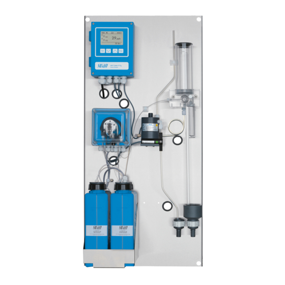
AMI Codes-II O3 Product Description 2.2. Instrument Overview Sample inlet Panel Transmitter Filter vessel (no filter) Peristaltic pump Photometer Oxycon on-line DPD reagent Air bubble detector Oxycon on-line Ozone reagent Constant head drain Constant head Photometer drain Flow regulating valve... -
Page 18: Installation
AMI Codes-II O3 Installation Installation 3.1. Installation Checklist On-site require- AC variant: 100–240 VAC ( 10%), 50/60 Hz ( 5%) ments DC variant: 10–36 VDC Power consumption: 35 VA maximum. Protective earth connection required. Sample line with sufficient sample flow and pressure (see Instru- ment Specification, p. -
Page 19: Mounting Of Instrument Panel
AMI Codes-II O3 Installation 3.2. Mounting of Instrument Panel The first part of this chapter describes the preparing and placing of the system for use. The instrument must only be installed by trained personnel. Mount the instrument in vertical position. -
Page 20: Fep Tube At Sample Outlet
AMI Codes-II O3 Installation 3.3.2 FEP Tube at Sample Outlet WARNING Risk of water pollution The drain of the photometer outlet contains DPD. At no means recirculate it into the water system. Tube from photometer Drain Photometer Tube from constant head... -
Page 21: Installation Of Flow Cell
Installation of Flow Cell CAUTION Fragile Part Handle the constant head tube with care. To avoid damage during the transport, the constant head tube [C] of the AMI Codes-II O3 is not installed. Constant head cover Overflow tube Constant head tube Gasket... -
Page 22: Electrical Connections
AMI Codes-II O3 Installation 3.5. Electrical Connections WARNING Risk of electrical shock Do not perform any work on electrical components if the transmit- ter is switched on. Failure to follow safety instructions could result in serious injury or death. Always turn off power before manipulating electric parts. - Page 23 AMI Codes-II O3 Installation WARNING External Voltage. External supplied devices connected to relay 1 or 2 or to the alarm relay can cause electrical shocks Make sure that the devices connected to the following contacts are disconnected from the power before resuming installation.
-
Page 24: Connection Diagram
AMI Codes-II O3 Installation 3.5.1 Connection Diagram CAUTION Use only the terminals shown in this diagram, and only for the mentioned purpose. Use of any other terminals will cause short circuits with possible corresponding consequences to material and personnel. A-96.250.881 / 070622... -
Page 25: Power Supply
Mains cable to comply with standards IEC 60227 or IEC requirements 60245; flammable rating FV1 Mains equipped with an external switch or circuit-breaker – near the instrument – easily accessible to the operator – marked as interrupter for AMI Codes-II O3 A-96.250.881 / 070622... -
Page 26: Opening The Peristaltic Pump Housing
AMI Codes-II O3 Installation 3.5.3 Opening the peristaltic pump housing For some electrical connections (see Connection Diagram, p. 24), it is necessary to open the housing of the peristaltic pump. To do this, proceed as follows: 1 Switch off the analyzer according to Stop of Operation for Mainte- nance, p. -
Page 27: Input
AMI Codes-II O3 Installation 3.6. Input Note: Use only potential-free (dry) contacts. The total resistance (sum of cable resistance and resistance of the relay contact) must be less than 50 Ω. Terminals 30 and 31. If the signal output is set to hold, the measurement is interrupted if input is active. -
Page 28: Relay 1 And 2
AMI Codes-II O3 Installation 3.7.2 Relay 1 and 2 Note: Max. load 1 A/250 VAC Relay 1 and 2 can be configured as normally open or as normally closed. Standard for both relays is normally open. To configure a Re- lay as normally closed, set the jumper in the upper position. - Page 29 AMI Codes-II O3 Installation CAUTION Risk of damage of the relays in the AMI Transmitter due to heavy inductive load. Heavy inductive or directly controlled loads (solenoid valves, dos- ing pumps) may destroy the relay contacts. To switch inductive loads > 0.1 A use an AMI relay box avail- able as an option or suitable external power relays.
-
Page 30: Signal Outputs
AMI Codes-II O3 Installation 3.8. Signal Outputs 3.8.1 Signal Output 1 and 2 (current outputs) Note: Max. burden 510 Ω If signals are sent to two different receivers, use signal isolator (loop isolator). Signal output 1: Terminals 14 (+) and 13 (-) -
Page 31: Signal Output 3
AMI Codes-II O3 Installation 3.9.1 Signal Output 3 Terminals 38 (+) and 37 (-). Requires the additional board for the third signal output 0/4–20 mA. The third signal output can be operated as a current source or as a current sink (switchable via switch [A]). For detailed information see the corresponding installation instruction. -
Page 32: Hart Interface
AMI Codes-II O3 Installation 3.9.3 HART Interface Terminals 38 (+) and 37 (-). The HART interface PCB allows for communication via the HART protocol. For detailed information, consult the HART manual. HART Interface PCB 3.9.4 USB Interface The USB Interface is used to store Logger data and for Firmware up- load. -
Page 33: Instrument Setup
AMI Codes-II O3 Instrument Setup Instrument Setup After installation according to checklist proceed as following: 4.1. Prepare Reagents 1 Prepare reagents. See Refill or replace Reagents, p. 2 Insert the suction lances into the canisters. 4.2. Peristaltic Pump The instrument is delivered with opened occlusion frames. -
Page 34: Establish Sample Flow
AMI Codes-II O3 Instrument Setup 4.3. Establish Sample Flow WARNING Water pollution The drain of the photometer outlet contains DPD. At no means recirculate it into the water system. Cover Constant head tube Overflow tube Flow cell block Level... -
Page 35: Fill Or Flush Reagent System
AMI Codes-II O3 Instrument Setup 4.4. Fill or Flush Reagent System Fill or flush the reagent tubing: upon the initial instrument setup, after refilling the reagent canisters, before a system shut-down to flush the system with demineralized water until no more reagent is left in the system. -
Page 36: Calibration
AMI Codes-II O3 Instrument Setup 4.6. Calibration Process Calibration of DIS, p. 50 Process DIS A process calibration is only possible with a process value higher than 10 ppb ozone. Please note that due to the low stability of the ozone, a process calibration with an elevated concentration is pre- ferred. -
Page 37: Operation
AMI Codes-II O3 Operation Operation 5.1. Keys Exit Enter to exit a menu or command (rejecting any changes) to move back to the previous menu level to move DOWN in a menu list and to decrease digits to move UP in a menu list and to increase digits... -
Page 38: Display
AMI Codes-II O3 Operation 5.2. Display 15:20:18 15:18:50 23 B/s A RUN normal operation HOLD input closed or cal delay: Instrument on hold (shows status of signal outputs). input closed: control/limit is interrupted (shows status of signal outputs). ERROR Error... -
Page 39: Software Structure
AMI Codes-II O3 Operation 5.3. Software Structure Main Menu Messages Diagnostics Maintenance Operation Installation Menu Messages 1 Messages Reveals pending errors as well as an event history Pending Errors (time and state of events that have occurred at an Message List earlier point of time). -
Page 40: Changing Parameters And Values
AMI Codes-II O3 Operation 5.4. Changing Parameters and values Changing The following example shows how to change the logger interval: parameters 1 Select the parameter you want to Sensors Logger 5.1.2 4.4.1 change. Sensor type FOME Log interval 30 min 2 Press [Enter] Disinf. -
Page 41: Maintenance
AMI Codes-II O3 Maintenance Maintenance 6.1. Maintenance Schedule Every 2–4 weeks Clean reagent canisters and prepare new reagents. Every 6 months Recommendation: Check photometer with verification kit Verification, p. Yearly Exchange reagent pump tubes, see Tube Replacement, p. By occurrence E010, Sample flow low: Check sample flow (see also Troubleshooting, p. -
Page 42: Stop Of Operation For Maintenance
AMI Codes-II O3 Maintenance 6.2. Stop of Operation for Maintenance 1 Put the suction lances into a bucket with demineralized water. 2 Start <Fill system>. The reagent tubes are flushed with water. 3 Remove the suction lances from the water. -
Page 43: Refill Or Replace Reagents
AMI Codes-II O3 Maintenance 6.3. Refill or replace Reagents The liquid level in canister 2 is monitored. The following messages are displayed: Canister almost Maintenance E065 - Reagents low and the empty remaining reagent volume in % (starting at 17 % = 340 ml). - Page 44 AMI Codes-II O3 Maintenance Reagent The 2 liter reagent canister will last for at least 33 days of operation with the default measurement interval of 6 minutes. The provided re- consumption agent set (for 3 canisters) therefore lasts for at least 3 months of op- eration.
-
Page 45: Reagents For Measuring Ozone
AMI Codes-II O3 Maintenance 6.3.1 Reagents for measuring Ozone Prepare 1 Rinse the canister [E] labelled OXYCON ON LINE DPD Reagent with demineralized water. Oxycon On-line DPD 2 Fill the canister up to the 2 liter mark with demineralized water. -
Page 46: Verification
Verification filters surfaces The verification procedure confirms the photometric accuracy and linearity of the core components of AMI Codes-II O3, i.e. photometer and converter electronics, over the entire measurement range by comparison of the absorbances measured by the AMI Codes-II O3 with the certified reference values. - Page 47 AMI Codes-II O3 Maintenance Reference Prior to performing the first verification and after each recertification, the reference values for the filters “low” and “high” need to be set in values menu 4.1.1 <Operation>\<Sensors>\<Verification kits>. The refer- ence values are specified in the enclosed calibration certificate.
- Page 48 AMI Codes-II O3 Maintenance 5 Align the triangle shape either to the front or backside and adjust for minimal absorbance (see AMI Display). 6 Press [Enter] to save the verification measurement. 7 Remove the verification filter “low” from the photometer and shake off large water droplets.
- Page 49 AMI Codes-II O3 Maintenance Storage and Observe the following points when handling the verification filters: When not in use, the verification filters should always be kept handling in the provided box. Avoid soiling of the optical surfaces as far as possible.
-
Page 50: Calibration
AMI Codes-II O3 Maintenance 6.5. Calibration Process Note: Perform process calibration only if: Calibration of • the sample concentration is close to the desired process value (stable value) • you are sure that the reagents are mixed completely and correctly •... -
Page 51: Cleaning The Photometer
AMI Codes-II O3 Maintenance 6.6. Cleaning the Photometer Clean the photometer after indication by alarm (E020, FOME dirty). Switch off the instrument according to instructions in Stop of Opera- tion for Maintenance, p. Material Small brush. Procedure Flow regulating valve... -
Page 52: Cleaning The Flow Cell
AMI Codes-II O3 Maintenance 6.7. Cleaning the Flow Cell CAUTION Acrylic glass parts are fragile and scratch-sensitive. Possible damage of acrylic glass parts due to scrubbing materi- als. Never use organic solvents or scrubbing materials to clean acrylic glass parts. -
Page 53: Assemble The Flow Cell
AMI Codes-II O3 Maintenance Cleaning 1 Switch off the instrument according to instructions in Stop of Op- eration for Maintenance, p. 42 2 Remove the constant head cover [A]. 3 Remove the constant head tube [C] from the flow cell block. -
Page 54: Tube Replacement
AMI Codes-II O3 Maintenance 6.8. Tube Replacement 6.8.1 Replace the Pump Tubes The pump tube [D] of the peristaltic pump is exposed to a minimal wear. It is therefore recommended to exchange the pump tube annu- ally. CAUTION Pollution of reagents possible. - Page 55 AMI Codes-II O3 Maintenance Dismount The pump tube can easily be dismounted and mounted. Proceed as follows: pump tubes Pump housing Occlusion frame open Rotor Pump tube Pump inlet Pump outlet 1 Switch off the instrument according to instructions in Stop of Op- eration for Maintenance, p.
-
Page 56: Longer Stop Of Operation
AMI Codes-II O3 Maintenance 6.9. Longer Stop of Operation 1 Put the suction lances into a bucket with demineralized water. 2 Start <Fill system>. The reagent tubes are flushed with water. 3 Remove the suction lance from the water. -
Page 57: Troubleshooting
AMI Codes-II O3 Troubleshooting Troubleshooting This chapter provides some hints to make troubleshooting easier. For any detailed information on how to handle or clean parts please Maintenance, p. 41. For any detailed information how to program the instrument please see Program List and Explanations, p. -
Page 58: Calibration Errors
AMI Codes-II O3 Troubleshooting 7.2. Calibration Errors 7.2.1 Process Calibration DIS Possible error Slope error: message Possible cause Corrective Action Wrong manual measure- Repeat the manual measurement. ment. Use fresh reagents. Wrong reagent mixture Make a correct mixture. -
Page 59: Error List
AMI Codes-II O3 Troubleshooting 7.4. Error List Error Non-fatal Error. Indicates an alarm if a programmed value is exceeded. Such Errors are marked E0xx (bold and black). Fatal Error (blinking symbol) Control of dosing devices is interrupted. The indicated measured values are possibly incorrect. - Page 60 AMI Codes-II O3 Troubleshooting Error Description Corrective action – check process E001 DIS. Alarm high – check programmed value in menu 5.3.1.1.1, p. 77 – check process E002 DIS. Alarm Low – check programmed value in menu 5.3.1.1.25, p. 77 –...
- Page 61 AMI Codes-II O3 Troubleshooting Error Description Corrective action – This error appears after start-up and will E021 DIS. invalid disappear after the first valid measurement is finished. – refill reagents, see Refill or replace E022 Reagent empty Reagents, p. 43 –...
-
Page 62: Replacing Fuses
AMI Codes-II O3 Troubleshooting 7.5. Replacing Fuses WARNING External Voltage. External supplied devices connected to relay 1 or 2 or to the alarm relay can cause electrical shocks. Make sure that the devices connected to the following contacts are disconnected from the power before resuming installation. -
Page 63: Program Overview
AMI Codes-II O3 Program Overview Program Overview All menus are password-protected as soon as an administrator pass- word has been defined. Menu 1 Messages informs about pending errors and mainte- nance tasks and shows the error history. Access by administra- tor, service and operator. -
Page 64: Diagnostics (Main Menu 2)
AMI Codes-II O3 Program Overview 8.2. Diagnostics (Main Menu 2) Identification * Menu numbers Designation AMI Codes-II O3 2.1* Version V6.21 - 01/18 Peripherals 2.1.3.1* PeriClip 1 / 1.05 2.1.3* Factory Test 2.1.4.1* Instrument 2.1.4* Motherboard Operating Time 2.1.5.1* Years / Days / Hours / Minutes / Seconds 2.1.5*... -
Page 65: Maintenance (Main Menu 3)
AMI Codes-II O3 Program Overview 8.3. Maintenance (Main Menu 3) Calibration Process DIS * Menu numbers Current Value 3.1* 3.1.1* Slope 3.1.1.4* Process Value Service Verification 3.2.1.1* (Progress) 3.2* 3.2.1* Fill System 3.2.2.5* (Progress) 3.2.2* Reagents Last change 3.2.3* Remaining days 3.2.3.3*... -
Page 66: Operation (Main Menu 4)
AMI Codes-II O3 Program Overview 8.4. Operation (Main Menu 4) Sensors Verification kits Verikit low 4.1.1.1* * Menu numbers 4.1* 4.1.1* Verikit high 4.1.1.2* 4.1.2* Filter Time Const. 4.1.3* Hold after Cal. 4.1.4* Meas. Interval Relay Contacts Alarm Relay Alarm DIS 4.2.1.1.1*... -
Page 67: Installation (Main Menu 5)
AMI Codes-II O3 Program Overview 8.5. Installation (Main Menu 5) Sensors 5.1.1* * Menu numbers Disinf. 5.1* Reag. expiry warning 5.1.2* Signal Outputs Signal Output 1&2 5.2.1.1 & 5.2.2.1* Parameter 5.2* 5.2.1* & 5.2.2* 5.2.1.2 & 5.2.2.2* Current Loop 5.2.1.3 & 5.2.2.3*... - Page 68 AMI Codes-II O3 Program Overview Miscellaneous 5.4.1* * Menu numbers Language 5.4* 5.4.2* Set defaults 5.4.3* Load Firmware Access Administrator Name 5.4.4* 5.4.4.1* Function Password User 1–4 Name 5.4.4.x* Function Password 5.4.5* Sample ID 5.4.6* Line Break Detection Interface 5.5.1* Protocol 5.5*...
-
Page 69: Program List And Explanations
AMI Codes-II O3 Program List and Explanations Program List and Explanations 1 Messages 1.1 Pending Errors 1.1.5 Provides the list of active errors with their status (active, acknowledged). If an active error is acknowledged, the alarm relay is active again. Cleared errors are moved to the Message list. - Page 70 AMI Codes-II O3 Program List and Explanations 2.2.1.4 Cal. History: Shows the diagnostic values of the last calibrations. Number: Calibration counter. Date, Time: Date and time of the calibration. Slope: Slope is a correction factor calculated on the basis of a process calibration.
-
Page 71: Maintenance
AMI Codes-II O3 Program List and Explanations 3 Maintenance 3.1 Calibration 3.1.1 Process DIS: Possibility to correct the disinfectant value. See Process Calibration of DIS, p. 50, for more details. 3.2 Service 3.2.1 Verification: Performs a verification using the reference kit. Follow dialog. -
Page 72: Operation
AMI Codes-II O3 Program List and Explanations 4 Operation 4.1 Sensors 4.1.1 Verification kits: 4.1.1.1 Verikit low: Set the absorbance value of the verification filter “low” ac- cording to the calibration certificate. Range: 0.0000–0.1000 4.1.1.2 Verikit high: Set the absorbance value of the verification filter “high”... -
Page 73: Installation
AMI Codes-II O3 Program List and Explanations 5 Installation 5.1 Sensors 5.1.1 Disinf: The measured value can be displayed in two ways: Ozone: the measured value is displayed as ppb O TC1: the measured value is displayed as ppb Cl 5.1.2... - Page 74 AMI Codes-II O3 Program List and Explanations As process The process value can be represented in 3 ways: linear, bilinear or logarithmic. See graphs below. values [mA] 0 / 4 linear X Measured value bilinear [mA] 0 / 4 1’000 10’000...
- Page 75 AMI Codes-II O3 Program List and Explanations As control Signal outputs can be used for driving control units. We distinguish different kinds of controls: output P-controller: The controller action is proportional to the devia- tion from the setpoint. The controller is characterized by the P- Band.
- Page 76 AMI Codes-II O3 Program List and Explanations Control upwards /downwards Setpoint: User-defined process value (Measured value or flow) P-Band: Range below (upwards control) or above (downwards control) the set-point, within the dosing intensity is reduced from 100% to 0% to reach the set-point without overshooting.
- Page 77 AMI Codes-II O3 Program List and Explanations 5.3.1.1 Alarm DIS. 5.3.1.1.1 Alarm High: If the measured value rises above the alarm high value, the alarm relay is activated and E001 is displayed in the message list. Range: 0.0–500.0 ppb 5.3.1.1.25...
- Page 78 AMI Codes-II O3 Program List and Explanations Note: The navigation in the menu <Relay 1> and <Relay 2> is equal. For reason of simplicity only the menu numbers of Relay 1 are used in the following. 1 First select the functions as:...
- Page 79 AMI Codes-II O3 Program List and Explanations 5.3.2.22 Parameter: Choose on of the following process values. DIS Sample Flow 5.3.2.32 Settings: Choose the respective actuator: Time proportional Frequency Motor valve 5.3.2.32.1 Actuator = Time proportional Examples of metering devices that are driven time proportional are solenoid valves, peristaltic pumps.
- Page 80 AMI Codes-II O3 Program List and Explanations 5.3.2.1 Function = Timer: The relay will be active repetitively depending on the programmed time scheme. 5.3.2.24 Mode: Operating mode (interval, daily, weekly) 5.3.2.24 Interval 5.3.2.340 Interval: The interval can be programmed within a range of 1–1’440 min.
- Page 81 AMI Codes-II O3 Program List and Explanations 5.3.2.44 Run Time: see Interval 5.3.2.54 Delay: see Interval 5.3.2.6 Signal Outputs: see Interval 5.3.2.7 Output/Control: see Interval 5.3.2.24 weekly The relay contact can be activated at one or several days, of a week.
- Page 82 AMI Codes-II O3 Program List and Explanations 5.3.4.2 Signal Outputs: Select the operation mode of the signal outputs when the relay is active: Signal outputs continue to issue the measured Cont.: value. Signal outputs issue the last valid measured value.
- Page 83 AMI Codes-II O3 Program List and Explanations 5.4.4 Access: Select a password to prevent unauthorized access to the menus <Messages>, <Diagnostics>, <Maintenance>, <Operation> and <Installation>. Note: The password protection becomes active under the following conditions: • Enter an administrator password different from <0000>.
- Page 84 AMI Codes-II O3 Program List and Explanations 5.4.5 Sample ID: Identify the process value with any meaning full text, such as KKS number. 5.4.6 Line Break Detection: If activated, error message E028 is shown in case of line break on signal outputs 1 and 2.
-
Page 85: Material Safety Data Sheets
AMI Codes-II O3 Material Safety Data Sheets Material Safety Data Sheets 10.1. Reagents Catalogue No.: A-85.410.210 Product name: OXYCON ON-LINE DPD Catalogue No.: A-85.410.210 Product name: OXYCON ON-LINE Buffer O3 Download The current Material Safety Data Sheets (MSDS) for the above listed Reagents are available for downloading at www.swan.ch. -
Page 86: Default Values
AMI Codes-II O3 Default Values Default Values Operation: Sensors: Verification kits: Verikit low: ............. 0.0900 Verification kits: Verikit high: ............ 0.1800 Filter Time Const.: ................30 s Hold after Cal.:................120 s Meas. Interval: ................6 min Alarm Relay .................same as in Installation Relay 1and 2 .................same as in Installation... - Page 87 AMI Codes-II O3 Default Values Hysteresis: ................1.0 ppb Delay:................... 30 s If Function = Control upw. or dnw: Parameter: ..................DIS Settings: Actuator: ............. Frequency Settings: Pulse Frequency: ..........120/min Settings: Control Parameters: Setpoint: ......500.0 ppb Settings: Control Parameters: P-band:........ 1.0 ppb Parameter: ..............
- Page 88 AMI Codes-II O3 Default Values Input: Active................when closed Signal Outputs ................hold Output/Control ................off Fault....................no Delay ....................10 s Miscellaneous Language:................English Set default: ..................no Load firmware:................no Access: Password: Administrator ..........0000 Access: Password: User 1...4: ........... 1234 Sample ID:................- - - - - - - -...
-
Page 89: Index
AMI Codes-II O3 Index Index ....Alarm Logger ...... - Page 90 AMI Codes-II O3 Index ....... USB Interface Wire ....
-
Page 91: Notes
AMI Codes-II O3 Notes Notes A-96.250.881 / 070622... - Page 92 Swan Products - Analytical Instruments for: Swan is represented worldwide by subsidiary companies and distributors and cooperates with independent representatives all over the world. For contact in- formation, please scan the QR code. Swan Analytical Instruments ∙ CH-8340 Hinwil www.swan.ch ∙ swan@swan.ch AMI Codes-II O3...
Need help?
Do you have a question about the AMI Codes-II O3 and is the answer not in the manual?
Questions and answers