Table of Contents
Advertisement
Quick Links
Advertisement
Table of Contents

Related Manuals for Swan Analytical Instruments AMI SAC254


Summary of Contents for Swan Analytical Instruments AMI SAC254
- Page 1 A-96.250.851 / 031120 Operator’s Manual Firmware V6.22 and higher AMI SAC254...
- Page 2 For any technical question, contact your nearest Swan representative, or the manufacturer: Swan Analytische Instrumente AG Studbachstrasse 13 8340 Hinwil Switzerland Internet: www.swan.ch E-mail: support@swan.ch Document Status AMI SAC254 Operator’s Manual Title: A-96.250.851 Revision Issue Jan. 2018 First edition August 2019 Instrument Version 1-B July 2020 Mainboard V2.6...
-
Page 3: Table Of Contents
AMI SAC254 Table of Contents Safety Instructions .......... - Page 4 AMI SAC254 Operation ........... . . 33 5.1.
-
Page 5: Safety Instructions
AMI SAC254 Safety Instructions AMI SAC254–Operator’s Manual This document describes the main steps for instrument setup, opera- tion and maintenance. Safety Instructions General The instructions included in this section explain the potential risks associated with instrument operation and provide important safety practices designed to minimize these risks. -
Page 6: Warning Notices
AMI SAC254 Safety Instructions 1.1. Warning Notices The symbols used for safety-related notices have the following meaning: DANGER Your life or physical wellbeing are in serious danger if such warn- ings are ignored. Follow the prevention instructions carefully. WARNING Severe injuries or damage to the equipment can occur if such warnings are ignored. - Page 7 AMI SAC254 Safety Instructions Warning Signs The warning signs in this manual have the following meaning: Electrical shock hazard Corrosive Harmful to health Flammable Warning general Attention general A-96.250.851 / 031120...
-
Page 8: General Safety Regulations
AMI SAC254 Safety Instructions 1.2. General Safety Regulations Legal The user is responsible for proper system operation. All precautions must be followed to ensure safe operation of the instrument. Requirements Spare Parts Use only official SWAN spare parts and disposables. If other parts are used during the normal warranty period, the manufacturer’s war-... -
Page 9: Product Description
2.1. Description of the System Application The AMI SAC254 is a complete monitoring system for the continu- ous measurement of UV absorption at 254 nm for organic carbon trending in potable water and waste water effluent. It includes an optional turbidity correction according to DIN EN 38404-3. - Page 10 Beam splitter 45° UV LED (254 nm) Green LED (550 nm) The AMI SAC254 is equipped with a two-wavelength photometer with one optical channel. The light beam [F] irradiates the cuvette [E] through the quartz window [I] from bottom to top.
- Page 11 AMI SAC254 Product Description Fluidics Photometer unit Waste funnel Cuvette Instrument sample inlet Pressure tube Blind plug / inlet for optional Capillary tube cleaning module Pressure reducing valve Grab sample valve Flow controller sample inlet Flow cell block Inlet strainer...
- Page 12 (DOC, TOC, BOD, etc.) via one-point or two-point calibration or manual configuration of the correlation parameters. If necessary, a calibration of the absorbance measurement is also possible, e.g. to adjust the values measured by the AMI SAC254 rel- ative to a reference instrument. Calibration, p.
-
Page 13: Instrument Specifications
AMI SAC254 Product Description 2.2. Instrument Specifications Power Supply 100–240 VAC (± 10%) AC variant: 50/60 Hz (± 5%) 10–36 VDC DC variant max. 35 VA Power consumption: Transmitter aluminum, with a protection degree of Housing: specifications IP 66 / NEMA 4X −10 to +50 °C... - Page 14 AMI SAC254 Product Description Dimensions Panel: 400x850x150 mm Dimensions: 5 mm or 6 mm diameter Screws: 12 kg Weight: 400 mm / 15.75" 374 mm / 14.72" Exit Enter AMI SAC254 30 mm / 1.18" A-96.250.851 / 031120...
-
Page 15: Instrument Overview
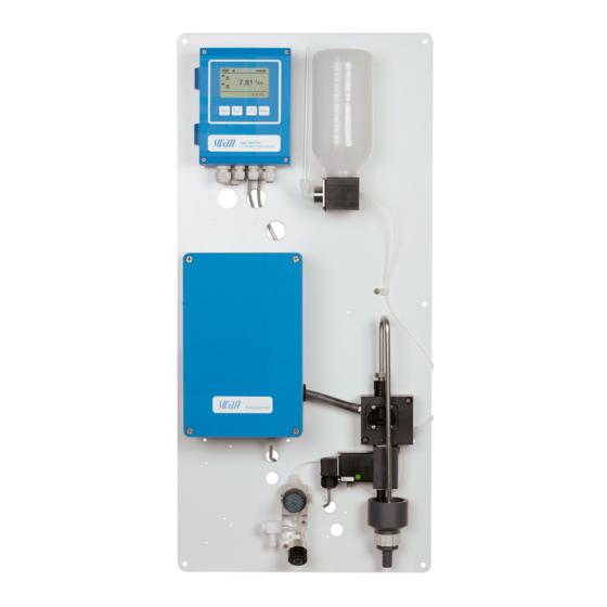
AMI SAC254 Product Description 2.3. Instrument Overview Exit Enter AMI SAC254 Ozone Monitor Panel Sample inlet of instrument Transmitter Inlet for optional cleaning module Grab sample valve Photometer unit Flow controller (option) Grab sample inlet Sample inlet of flow Siphon... -
Page 16: Installation
AMI SAC254 Installation Installation 3.1. Installation Checklist On-site AC variant: 100–240 VAC ( 10%), 50/60 Hz ( 5%) requirements DC variant: 10–36 VDC Power consumption: 35 VA maximum. Protective earth connection required. Sample line with sufficient sample flow and pressure (see Instru- ment Specifications, p. -
Page 17: Mounting Of Instrument Panel
AMI SAC254 Installation 3.2. Mounting of Instrument Panel The first part of this chapter describes the preparing and placing of the system for use. The instrument must only be installed by trained personnel. Exactly align the instrument in vertical and horizontal position. - Page 18 AMI SAC254 Installation Sample inlet Hose nozzle with 1/8” (with flow thread controller) 10 mm tube Connect a 10 mm tube to the hose nozzle [B]. Waste Waste funnel Hose nozzle 20 mm tube Connect a 20 mm tube [C] to the hose nozzle [B] and place it into a pressure free drain.
-
Page 19: Aligning The Photometer
AMI SAC254 Installation 3.4. Aligning the Photometer Horizontal adjustment screw Cuvette Vertical adjustment screw Spirit level After installation, align the photometer using screws [A] and [C]. A-96.250.851 / 031120... -
Page 20: Electrical Connections
AMI SAC254 Installation 3.5. Electrical Connections WARNING Risk of electrical shock. Do not perform any work on electrical components if the transmit- ter is switched on. Failure to follow safety instructions could result in serious injury or death. Always turn off power before manipulating electric parts. - Page 21 AMI SAC254 Installation WARNING External Voltage. External supplied devices connected to relay 1 or 2 or to the alarm relay can cause electrical shocks Make sure that the devices connected to the following contacts are disconnected from the power before resuming installation.
-
Page 22: Connection Diagram
AMI SAC254 Installation 3.5.1 Connection Diagram CAUTION Use only the terminals shown in this diagram, and only for the mentioned purpose. Use of any other terminals will cause short circuits with possible corresponding consequences to material and personnel. A-96.250.851 / 031120... -
Page 23: Power Supply
Mains cable to comply with standards IEC 60227 or IEC requirements 60245; flammable rating FV1 Mains equipped with an external switch or circuit-breaker – near the instrument – easily accessible to the operator – marked as interrupter for AMI SAC254 A-96.250.851 / 031120... -
Page 24: Relay Contacts
AMI SAC254 Installation 3.6. Relay Contacts Programming of the relay contacts see 5.3 Relay Contacts, p. 74 3.6.1 Input Note: Use only potential-free (dry) contacts. The total resistance (sum of cable resistance and resistance of the relay contact) must be less than 50 Ω. -
Page 25: Relay Contacts 1 And 2
AMI SAC254 Installation 3.6.3 Relay Contacts 1 and 2 Note: Rated load 1 AT / 250 VAC Relay 1 and 2 can be configured as normally open or as normally closed. Standard for both relays is normally open. To configure a Re- lay as normally closed, set the jumper in the upper position. - Page 26 AMI SAC254 Installation CAUTION Risk of damage of the relays in the AMI Transmitter due to heavy inductive load. Heavy inductive or directly controlled loads (solenoid valves, dos- ing pumps) may destroy the relay contacts. To switch inductive loads > 0.1 A use an AMI relay box avail- able as an option or suitable external power relays.
-
Page 27: Signal Outputs
AMI SAC254 Installation 3.7. Signal Outputs 3.7.1 Signal Output 1 and 2 (current outputs) Note: Max. burden 510 Ω. If signals are sent to two different receivers, use signal isolator (loop isolator). Signal output 1: Terminals 14 (+) and 13 (-) -
Page 28: Signal Output 3
AMI SAC254 Installation 3.8.1 Signal Output 3 Terminals 38 (+) and 37 (-). Requires the additional board for the third signal output 0/4–20 mA. The third signal output can be operated as a current source or as a current sink (switchable via switch [A]). For detailed information see the corresponding installation instruction. -
Page 29: Hart Interface
AMI SAC254 Installation 3.8.3 HART Interface Terminals 38 (+) and 37 (-). The HART interface PCB allows for communication via the HART protocol. For detailed information, consult the HART manual. HART Interface PCB 3.8.4 USB Interface The USB Interface is used to store Logger data and for Firmware up- load. -
Page 30: Instrument Setup
AMI SAC254 Instrument Setup Instrument Setup 4.1. Establish Sample Flow 1 Start sample flow. Set the flow rate according to Instrument Spec- ifications, p. 2 Switch on power. 4.2. Programming Set all necessary sensor parameters in menu 5.1 <Installation>/ <Sensors>. For further information see 5.1 Sensors, p. -
Page 31: Fine Tuning Of Turbidity Correction
4.5. Fine tuning of turbidity correction The turbidity correction of the AMI SAC254 is based on the DIN EN 38404-3 standard. According to this standard, a reference measure- ment at 550 nm is subtracted from the measurement at 254 nm. The standard does not provide for a scaling of the reference measure- ment. - Page 32 AMI SAC254 Instrument Setup Example 00:00 00:00 00:00 00:00 00:00 00:00 01.01 02.01 03.01 04.01 05.01 06.01 X Time [d] Y SAC corr [/m] Coefficient 0.0 Coefficient 1.0 Coefficient 1.3 Coefficient 2.0 When analyzing the curve, pay special attention to events that cause increased turbidity (e.
-
Page 33: Operation
AMI SAC254 Operation Operation 5.1. Keys Exit Enter to exit a menu or command (rejecting any changes) to move back to the previous menu level to move DOWN in a menu list and to decrease digits to move UP in a menu list and to increase digits... -
Page 34: Display
AMI SAC254 Operation 5.2. Display 15:20:18 15:20:00 0.000 0.0 l/h normal operation HOLD input closed or cal delay: Instrument on hold (shows status of signal outputs). input closed: control/limit is interrupted (shows status of signal outputs). ERROR Error Fatal Error... -
Page 35: Software Structure
AMI SAC254 Operation 5.3. Software Structure Main Menu Messages Diagnostics Maintenance Operation Installation Menu Messages 1 Messages Reveals pending errors as well as an event history Pending Errors (time and state of events that have occurred at an Maintenance List earlier point of time). -
Page 36: Changing Parameters And Values
AMI SAC254 Operation 5.4. Changing Parameters and Values Changing The following example shows how to change the logger interval: parameters 1 Select the parameter you want to Sensors Logger 5.1.2 4.4.1 change. Sensor type FOME Log interval 30 min 2 Press [Enter] Disinf. -
Page 37: Grab Sample
AMI SAC254 Operation 5.5. Grab Sample The grab sample function can be used for manual measurement of a sample or to check the instrument performance using a user-defined standard solution. The result is saved in the grab sample history (see 2.2.3.3, p. -
Page 38: Maintenance
AMI SAC254 Maintenance Maintenance 6.1. Maintenance Table If required Clean the instrument manually, see 6.3., (if no cleaning module is installed). Clean the inlet strainer, see 6.4., 39. Clean the cuvette, see 6.5., 40. -
Page 39: Cleaning The Inlet Strainer
AMI SAC254 Maintenance 6.4. Cleaning the Inlet Strainer Inlet strainer Screw cap 1 Stop sample flow. 2 Select <Operation>/<Service>/<Empty system>. Wait until the in- strument is empty. 3 Unscrew and remove the screw cap [A] and the strainer [B] from the flow cell. -
Page 40: Cleaning The Cuvette
AMI SAC254 Maintenance 6.5. Cleaning the Cuvette Cuvette tube O-ring Knurled screws Quartz window Flange Base plate Procedure Status of relays and signal outputs during the procedure: Signal outputs are on hold All limits are switched off 1 Navigate to menu <Maintenance>/<Cuvette cleaning>. -
Page 41: Calibration
AMI SAC254 Maintenance 6.6. Calibration The AMI SAC254 issues the three process values absorbance, UV transmission and concentration, of which the absorbance and con- centration can be independently calibrated. The UV transmission is calculated from the absorbance, therefore no independent calibra- tion of this process value is possible. -
Page 42: Process Calibration
The process calibration consists of the following steps: Take a sample and send it to a laboratory. At the same time, register the reading of the AMI SAC254 (steps 1 to 6). Once available, enter the reference value obtained from the laboratory (steps 7 to 11). -
Page 43: External Calibration
Each time, write down the absorbance reading of the AMI SAC254. Divide the absorbance values of the AMI SAC254 by the calibration slope (visible under <Diagnostics>/<Sensors>/<His- tory>/<Cal. History Abs.>). Analyze the samples in the laboratory to obtain the reference values. -
Page 44: Standard Calibration
AMI SAC254 Maintenance 6.6.3 Standard calibration Two-point calibration using two standard solutions of known absor- bance or concentration. Preparations The two standard solutions have to be prepared by the customer. One liter of each standard solution is needed. Points to consider: ... -
Page 45: Verification
AMI SAC254 Maintenance 6.7. Verification The verification checks the stability of the instrument using a certified standard solution provided by Swan. For this purpose, the raw SAC254 value is compared with a reference value indicated on the standard bottle. The result is saved in the verification history (see 2.2.3.4, p. -
Page 46: Longer Stop Of Operation
AMI SAC254 Maintenance If the deviation between the measured value and the reference value is too high, clean the instrument according to sections Manual Chemical Cleaning, p. 38 Cleaning the Cuvette, p. 40. Then re- peat the verification. 6.8. Longer Stop of Operation 1 Stop sample flow. -
Page 47: Troubleshooting
AMI SAC254 Troubleshooting Troubleshooting 7.1. Error List Error Non-fatal Error. Indicates an alarm if a programmed value is exceed- ed. Such Errors are marked E0xx (bold and black). Fatal Error (blinking symbol) Control of dosing devices is interrupted. The indicated measured values are possibly incorrect. - Page 48 AMI SAC254 Troubleshooting Error Description Corrective action – Check process. E001 SAC 254 Alarm high – Check programmed value 5.3.1.1.1, p. – Check process. E002 SAC 254 Alarm low – Check programmed value 5.3.1.1.25, p. – Check process. E003 UV Transm. Alarm high –...
- Page 49 AMI SAC254 Troubleshooting Error Description Corrective action – The turbidity correction results in a E011 Turbidity Correction negative absorbance value. Possible causes: The coefficient is set too high. Check programmed value in 5.1.1.2, p. The sample absorbs at 550 nm.
- Page 50 AMI SAC254 Troubleshooting Error Description Corrective action – Instruments without Cleaning Module-II: E018 SAC disconnected Check connection between the AMI transmitter and the photometer. – Instruments with Cleaning Module-II: Check connection between the cleaning module pump and the photometer. – Check connection of the sensor.
- Page 51 AMI SAC254 Troubleshooting Error Description Corrective action – None, normal status. E034 Power-down – Clean the cuvette. E065 Cuvette dirty – If the error persists, call service. – Observe several filling/emptying cycles. If E066 Siphon blocked emptying via the siphon tube works reliably, acknowledge this error.
-
Page 52: Cleaning The Siphon Tube
AMI SAC254 Troubleshooting 7.2. Cleaning the siphon tube If the siphon tube is heavily contaminated, it can be unscrewed and cleaned. Siphon tube Suction piece Knurled screw Flow cell Washer Tube bend O-ring 1 Unscrew the knurled screw [B]. Note: Do not unscrew the suction piece [E]. -
Page 53: Calculation Of Process Values
AMI SAC254 Troubleshooting 7.3. Calculation of process values The values of the AMI SAC254 are calculated as follows: SAC 254 raw SAC 550 raw SAC corr SAC 254 Concentration UV Transmission Value Description SAC 254 raw Raw value of the measurement at 254 nm. This value is visible in the diagnostics menu 2.2.1, p. - Page 54 AMI SAC254 Troubleshooting Value Description slope_abs Slope of the absorption measurement. This value is adjusted during the local calibration and can be seen in the calibration history 2.2.3.1, p. slope_conc Slope of the concentration measurement. This value is adjusted during the local calibration and can be seen in the calibration history 2.2.3.2, p.
-
Page 55: Replacing Fuses
AMI SAC254 Troubleshooting 7.4. Replacing Fuses WARNING External Voltage. External supplied devices connected to relay 1 or 2 or to the alarm relay can cause electrical shocks. Make sure that the devices connected to the following contacts are disconnected from the power before resuming installation. -
Page 56: Program Overview
AMI SAC254 Program Overview Program Overview For explanations about each parameter of the menus see Program List and Explanations, p. Menu 1 Messages informs about pending errors and mainte- nance tasks and shows the error history. Password protection possible. No settings can be modified. - Page 57 AMI SAC254 Program Overview Factory Test 2.1.4.1* * Menu numbers Instrument 2.1.4* Motherboard Front End Operating Time Years / Days / Hours / Minutes / Seconds 2.1.5.1* 2.1.5* Sensors Photometer Unit SAC254 2.2.1.1.1* SAC254 2.2* 2.2.1* 2.2.1.1* SAC254 raw SAC550 raw...
-
Page 58: Maintenance (Main Menu 3)
AMI SAC254 Program Overview Grab Sample. Number 2.2.3.3.1* 2.2.3.3* Date, Time Sample ID Sample Verif. History Number 2.2.3.4.1* 2.2.3.4* Date, Time Meas. Value Reference value Deviation Sample 2.3.1* Sample ID 2.3* Sample Flow I/O State 2.4.1* Alarm Relay 2.4* 2.4.2*... - Page 59 AMI SAC254 Program Overview Simulation 3.5.1* Alarm Relay 3.5* 3.5.2* Relay 1 3.5.3* Relay 2 Signal Output 1 3.5.4* 3.5.5* Signal Output 2 3.5.6* Magnetic valve Set Time (Date), (Time) 3.6* Cleaning Parameters Mode 3.7.1.1* 3.7* 3.7.1* Interval 3.7.1.20* Interval 3.7.1.1*...
-
Page 60: Operation (Main Menu 4)
AMI SAC254 Program Overview 8.4. Operation (Main Menu 4) Grab Sample 4.1.5* * Menu numbers (Progress) Sensors 4.2.1* Hold after Cal. 4.2* Relay Contacts Alarm Relay SAC254 4.3.1.1.1* Alarm High 4.3* 4.3.1* 4.3.1.1* 4.3.1.1.22* Alarm Low Hysteresis 4.3.1.1.32* 4.3.1.1.42* Delay 4.3.1.2.1*... -
Page 61: Installation (Main Menu 5)
AMI SAC254 Program Overview 8.5. Installation (Main Menu 5) Sensors SAC254 Turbidity correction 5.1.1.1.1* Turbidity correction 5.1* 5.1.1* 5.1.1.1* 5.1.1.1.2* Coefficient 5.1.1.31* Average meas. 5.1.1.41* Optical path length 5.1.1.51* Concentration Standards Absorbance Standard 1 5.1.2* 5.1.2.1* Standard 2 Concentration Standard 1 5.1.2.2*... - Page 62 AMI SAC254 Program Overview Input 5.3.4.1* * Menu numbers Active 5.3.4* 5.3.4.2* Signal Outputs 5.3.4.3* Output/Control 5.3.4.4* Fault 5.3.4.5* Delay Miscellaneous 5.4.1* Language 5.4* 5.4.2* Set defaults 5.4.3* Load Firmware Password 5.4.4.1* Messages 5.4.4* 5.4.4.2* Maintenance Operation 5.4.4.3* 5.4.4.4* Installation 5.4.5*...
-
Page 63: Program List And Explanations
AMI SAC254 Program List and Explanations Program List and Explanations 1 Messages 1.1 Pending Errors 1.1.5 Provides the list of active errors with their status (active, acknowl- edged). If an active error is acknowledged, the alarm relay is active again. Cleared errors are moved to the Message list. - Page 64 AMI SAC254 Program List and Explanations I0254 Light intensity of the UV LED measured with an empty cuvette (raw signal in V). A low signal indi- cates that the quartz window is dirty or that the UV LED needs to be replaced.
- Page 65 AMI SAC254 Program List and Explanations 2.2.3 History: Shows the values of the last calibrations, verifications and grab sample measurements. 2.2.3.1 Cal. History Absorbance Number: Calibration counter Date, Time: Date and time of calibration Slope: Calibration factor Max. 64 data records are memorized.
-
Page 66: Maintenance
AMI SAC254 Program List and Explanations 2.5 Interface Only available if optional interface is installed. Review programmed communication settings. 3 Maintenance 3.1 Calibration Calibration, p. 3.2 Process Calibration Process calibration, p. 3.3 Verification Verification, p. 3.4 Cuvette Cleaning Cleaning the Cuvette, p. - Page 67 AMI SAC254 Program List and Explanations 3.7 Cleaning Automatic cleaning process using the optional Cleaning Module-II. Cleaning is not possible if one of the following errors is active: E009/E010 Sample flow high/low E018 SAC disconnected E021 pressure sensor error ...
-
Page 68: Operation
AMI SAC254 Program List and Explanations If Mode = weekly The start of the automatic cleaning cycle can be set to one or more weekdays and any time of day. The programmed time of day is valid for all selected weekdays. -
Page 69: Installation
AMI SAC254 Program List and Explanations SAC254 raw, SAC550 raw, I0254, photodiode signal, water level, case temperature. 4.4.1 Log Interval: Select a convenient log interval. Consult the table be- low to estimate the max logging time. When the logging buffer is full, the oldest data record is erased to make room for the newest one (circular buffer). - Page 70 AMI SAC254 Program List and Explanations 5.1.1.31 Average meas.: Number of measuring points from which the moving average is calculated. The value can be increased to dampen noisy signals. The higher the number of measuring points, the slower the system reacts to changes of the measured value.
- Page 71 AMI SAC254 Program List and Explanations 5.2.1.3 Function: Define if the signal output is used to transmit a process val- ue or to drive a control unit. Available functions are: Linear, bilinear or logarithmic for process values. As process values, p. 71 ...
- Page 72 AMI SAC254 Program List and Explanations If Parameter = UV Transmission 5.2.1.40.11 Range low: 0.0%–100.0% 5.2.1.40.21 Range high: 0.0%–100.0% If Parameter = Concentration 5.2.1.40.12 Range low: 0.0 ppb–1.00 ‰ 5.2.1.40.22 Range high: 0.0 ppb–1.00 ‰ If Parameter = Sample Flow 5.2.1.40.12...
- Page 73 AMI SAC254 Program List and Explanations Ziegler-Nichols method for the optimization of a PID controller: Parameters: Setpoint, P-Band, Reset time, Derivative time Response to maximum control output = 1.2/a Tangent on the inflection point = 2L Time = L/2 The point of intersection of the tangent with the respective axis will result in the parameters a and L.
- Page 74 AMI SAC254 Program List and Explanations 5.2.1.43 Control Parameters: if Parameter = Concentration 5.2.1.43.12 Setpoint Range: 0.00 ppb–1.00‰ 5.2.1.43.22 P-Band Range: 0.00 ppb–1.00‰ 5.2.1.43 Control Parameters: if Parameter = Sample Flow 5.2.1.43.12 Setpoint Range: 0.0 l/h–15.0 l/h 5.2.1.43.22 P-Band Range: 0.0 l/h–15.0 l/h 5.2.1.43.3...
- Page 75 AMI SAC254 Program List and Explanations 5.3.1.1 SAC254 5.3.1.1.1 Alarm High: If the measured value rises above the alarm high value, the alarm relay is activated and E001 is displayed in the message list. Range: 0.0000 cm –3.000 cm 5.3.1.1.25...
- Page 76 AMI SAC254 Program List and Explanations 5.3.1.3.35 Hysteresis: Within the hyst. range, the relay does not switch. This prevents damage of relays contacts when the measured value fluctu- ates around the alarm value. Range. 0.00 ppb–1.00‰ 5.3.1.3.45 Delay: Waiting time before the alarm relay is activated if the mea- sured value has exceeded or fallen below the programmed alarm value.
- Page 77 AMI SAC254 Program List and Explanations 2 Then enter the necessary data depending on the selected func- tion. 5.3.2.1 Function = Limit upper/lower: When the relays are used as upper or lower limit switches, program the following: 5.3.2.20 Parameter: select a process value 5.3.2.300...
- Page 78 AMI SAC254 Program List and Explanations 5.3.2.32 Settings Choose the respective actuator: Time proportional Frequency Motor valve Actuator = Time proportional Examples of metering devices that are driven time proportional are solenoid valves, peristaltic pumps. Dosing is controlled by the operating time.
- Page 79 AMI SAC254 Program List and Explanations 5.3.2.24 Mode: Operating mode Mode interval daily weekly 5.3.2.24 Interval 5.3.2.340 Interval: The interval can be programmed within a range of 1–1440 min 5.3.2.44 Run Time: Enter the time the relay stays active. Range: 5–32400 s 5.3.2.54...
- Page 80 AMI SAC254 Program List and Explanations Range: 00:00:00–23:59:59 5.3.2.44 Run Time: see Interval 5.3.2.54 Delay: see Interval 5.3.2.6 Signal Outputs: see Interval 5.3.2.7 Output/Control: see Interval 5.3.2.24 weekly The relay contact can be activated on one or several days of a week.
- Page 81 AMI SAC254 Program List and Explanations Off: Set to 0 or 4 mA respectively. Errors, except fatal errors, are not issued. 5.3.4.3 Output/Control: (relay or signal output): Continuous: Controller continues normally. Hold: Controller continues on the last valid value. Off: Controller is switched off.
- Page 82 AMI SAC254 Program List and Explanations 5.4.3 Load Firmware: Firmware updates should be done by instructed ser- vice personnel only. Load Firmware 5.4.4 Password: Select a password different from 0000 to prevent unau- thorized access to the following menus: 5.4.4.1 Messages 5.4.4.2...
-
Page 83: Default Values
AMI SAC254 Default Values Default Values Operation Sensors Hold after Cal.:................300 s Alarm Relay .................same as in Installation Relay 1 and 2 .................same as in Installation Input .................same as in Installation Logger Logger Interval:............... 30 min Clear Logger: .................. no Display Displayed value ..............SAC254... - Page 84 AMI SAC254 Default Values Hysteresis:................500 ppb Delay: ..................180 s Sample Flow; Flow Alarm ..............yes Sample Flow; Alarm high............12.0 l/h Sample Flow; Alarm low ............2.0 l/h Case temp. high: ............... 65 °C Case temp. low:................0 °C Relay 1 and 2 Function:................limit upper...
- Page 85 AMI SAC254 Default Values Run time: ................. 60 s Neutral zone: ................5% If Function = Timer: Mode:..................Interval Interval:................... 1 min Mode: ..................daily Start time: ................00.00.00 Mode:..................weekly Calendar; Start time: ............00.00.00 Calendar; Monday to Sunday:............ Off Run time: ..................
-
Page 86: Index
AMI SAC254 Index Index ....... . Absorbance HART ... . - Page 87 AMI SAC254 Index ..System, Description of ..Relay Contacts 1 and 2 ....
-
Page 88: Notes
AMI SAC254 Notes Notes A-96.250.851 / 031120... - Page 89 AMI SAC254 Notes A-96.250.851 / 031120...
- Page 90 Swan Products - Analytical Instruments for: Swan is represented worldwide by subsidiary companies and distributors and cooperates with independent representatives all over the world. For contact information, please scan the QR code. Swan Analytical Instruments ∙ CH-8340 Hinwil www.swan.ch ∙ swan@swan.ch AMI SAC254...
Need help?
Do you have a question about the AMI SAC254 and is the answer not in the manual?
Questions and answers