Table of Contents
Advertisement
Quick Links
Advertisement
Chapters
Table of Contents

Related Manuals for Swan Analytical Instruments AMI Inducon


Summary of Contents for Swan Analytical Instruments AMI Inducon
- Page 1 AMI Inducon Version 6.20 and higher A-96.250.471 / 030720...
- Page 2 SWAN representative, or the manufacturer: SWAN ANALYTISCHE INSTRUMENTE AG Studbachstrasse 13 8340 Hinwil Switzerland Internet: www.swan.ch E-mail: support@swan.ch Document Status AMI Inducon Operator’s Manual Title: A-96.250.471 Revision Issue Sept. 2006 First Edition Feb. 2015 Update to FW Release 5.30, Mainboard V2.4 June 2017 Update to FW Release 6.20, Mainboard V2.5...
-
Page 3: Table Of Contents
Single components ........2.2.1 AMI Inducon Transmitter......2.2.2 Swansensor Inducon1000. - Page 4 AMI Inducon Maintenance ........
-
Page 5: Safety Instructions
AMI Inducon Safety Instructions AMI Inducon–Operator’s Manual This document describes the main steps for instrument setup, oper- ation and maintenance. Safety Instructions General The instructions included in this section explain the potential risks associated with instrument operation and provide important safety practices designed to minimize these risks. -
Page 6: Warning Notices
AMI Inducon Safety Instructions 1.1. Warning Notices The symbols used for safety-related notices have the following meaning: DANGER Your life or physical wellbeing are in serious danger if such warnings are ignored. Follow the prevention instructions carefully. WARNING Severe injuries or damage to the equipment can occur if such warnings are ignored. - Page 7 AMI Inducon Safety Instructions Warning Signs The meaning of the warning signs in this manual: Electrical shock hazard Corrosive Harmful to health Flammable Warning general Attention general A-96.250.471 / 030720...
-
Page 8: General Safety Regulations
AMI Inducon Safety Instructions 1.2. General Safety Regulations Legal The user is responsible for proper system operation. All precau- tions must be followed to ensure safe operation of the instrument. Requirements Spare Parts Use only official SWAN spare parts and disposables. If other parts are used during the normal warranty period, the manufacturer’s... -
Page 9: Product Description
(TDS). Application The conductivity is a parameter for the total quantity of ions present in the solution. range The AMI Inducon transmitter together with the sensor Inducon1000 is used for applications in: chemical food & dairy refinery ... - Page 10 AMI Inducon Product Description Signal Two signal outputs programmable for measured values (freely scal- able, linear, bilinear, log) or as continuous control output (control Outputs parameters programmable). Current loop: 0/4–20 mA Maximal burden: 510 Ohm Third signal output available as an option. The third signal output can be operated as a current source or as a current sink (selectable via switch).
-
Page 11: Single Components
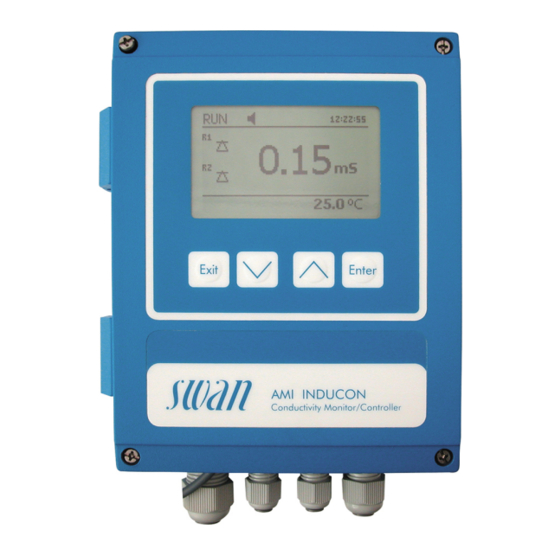
AMI Inducon Product Description 2.2. Single components 2.2.1 AMI Inducon Transmitter Power Supply AC variant: 100–240 VAC (± 10%) 50/60 Hz (± 5%) DC variant 10–36 VDC Power consumption: max. 35 VA Transmitter Housing: aluminum, with a protection degree of... -
Page 12: Swansensor Inducon1000
AMI Inducon Product Description 2.2.2 Swansensor Inducon1000 Technical Data Measuring range 0.2 to 2.000 mS/cm Temperature sensor Pt1000 Max. flow rate 3 m/s Electrical connections Directly attached cable with end sleeves Sanitary Style 39.6 mm (CIP) Sensor (1.56 inches) 5/8-11 UNC 50.8 mm (2.06 inches) -
Page 13: Installation
AMI Inducon Installation Installation 3.1. Installation Checklist On-site AC variant: 100–240 VAC ( 10%), 50/60 Hz ( 5%) requirements DC variant: 10–36 VDC Power consumption: 35 VA maximum. Protective earth connection required. Installation Mounting of Transmitter, p. 12 Electrical Connect all external devices like limit switches, current loops Wiring and pumps. -
Page 14: Mounting Of Transmitter
AMI Inducon Installation 3.2. Mounting of Transmitter The first part of this chapter describes the preparing and placing of the instrument for use. The transmitter must only be installed by trained personnel. Mount the transmitter in vertical position. -
Page 15: Connect The Conductivity Sensor
AMI Inducon Installation 3.3. Connect the Conductivity Sensor Connect the To connect the conductivity sensor cable to the AMI Transmitter proceed as follows: Sensor Cable WARNING Electrical shock hazard! Before opening the AMI Transmitter switch power off. 1 Choose a suitable cable gland, see chapter Electrical Connec- tions, p. -
Page 16: Electrical Connections
AMI Inducon Installation 3.4. Electrical Connections WARNING Risk of electrical shock. Do not perform any work on electrical components if the trans- mitter is switched on. Failure to follow safety instructions could result in serious injury or death. Always turn off power before manipulating electric parts. - Page 17 AMI Inducon Installation WARNING External Voltage. External supplied devices connected to relay 1 or 2 or to the alarm relay can cause electrical shocks Make sure that the devices connected to the following con- tacts are disconnected from the power before resuming in- stallation.
-
Page 18: Connection Diagram
AMI Inducon Installation 3.4.1 Connection Diagram CAUTION Use only the terminals shown in this diagram, and only for the mentioned purpose. Use of any other terminals will cause short circuits with possible corresponding consequences to material and personnel. A-96.250.471 / 030720... -
Page 19: Power Supply
Mains cable to comply with standards IEC 60227 or IEC 60245; flammable rating FV1 Mains equipped with an external switch or circuit-breaker – near the instrument – easily accessible to the operator – marked as interrupter for AMI Inducon A-96.250.471 / 030720... -
Page 20: Relay Contacts
AMI Inducon Installation 3.5. Relay Contacts 3.5.1 Input NOTICE: Use only potential-free (dry) contacts. The total resistance (sum of cable resistance and resistance of the relay contact) must be less than 50 Ω. Terminals 16/42 For programming see Program List and Explanations, p. -
Page 21: Relay 1 And 2
AMI Inducon Installation 3.5.3 Relay 1 and 2 NOTICE: Max. load 1 A/250 VAC Relay 1 and 2 can be configured as normally open or as normally closed. Standard for both relays is normally open. To configure a Relay as normally closed, set the jumper in the upper position. - Page 22 AMI Inducon Installation CAUTION Risk of damage of the relays in the AMI Transmitter due to heavy inductive load. Heavy inductive or directly controlled loads (solenoid valves, dosing pumps) may destroy the relay contacts. To switch inductive loads > 0.1 A use an AMI relay box avail- able as an option or suitable external power relays.
-
Page 23: Signal Outputs
AMI Inducon Installation 3.6. Signal Outputs 3.6.1 Signal Output 1 and 2 (current outputs) NOTICE: Max. burden 510 Ω If signals are sent to two different receivers, use signal isolator (loop isolator). Signal output 1: Terminals 14 (+) and 13 (-) -
Page 24: Signal Output 3
AMI Inducon Installation 3.7.1 Signal Output 3 Terminals 38 (+) and 37 (-). Requires the additional board for the third signal output 0/4–20 mA. The third signal output can be operated as a current source or as a current sink (switchable via switch [A]). For detailed information see the corresponding installation instruction. -
Page 25: Hart Interface
AMI Inducon Installation 3.7.3 HART Interface Terminals 38 (+) and 37 (-). The HART interface PCB allows for communication via the HART protocol. For detailed information, consult the HART manual. HART Interface PCB 3.7.4 USB Interface The USB Interface is used to store Logger data and for Firmware upload. -
Page 26: Instrument Setup
AMI Inducon Instrument Setup Instrument Setup 4.1. Programming After the AMI Transmitter has been installed and all components have been connected to the transmitter, switch on power. Navigate to menu <Installation>/<Sensors> and program the following pa- rameters: Menu 5.1.1:Sensor parameters –... -
Page 27: Operation
AMI Inducon Operation Operation 5.1. Keys Exit Enter to exit a menu or command (rejecting any changes) to move back to the previous menu level to move DOWN in a menu list and to decrease digits to move UP in a menu list and to increase digits... -
Page 28: Display
AMI Inducon Operation 5.2. Display 15:20:18 0.15 23 °C 23 l/h normal operation HOLD input closed or cal delay: Instrument on hold (shows status of signal outputs). input closed: control/limit is interrupted (shows status of signal outputs). ERROR Error Fatal Error... -
Page 29: Software Structure
AMI Inducon Operation 5.3. Software Structure Main Menu Messages Diagnostics Maintenance Operation Installation Menu Messages 1 Messages Reveals pending errors as well as an event history Pending Errors (time and state of events that have occurred at an Message List earlier point of time). -
Page 30: Changing Parameters And Values
AMI Inducon Operation 5.4. Changing Parameters and values Changing The following example shows how to change the logger interval: parameters 1 Select the parameter you want to Sensors Logger 5.1.2 4.4.1 change. Sensor type FOME Log interval 30 min 2 Press [Enter] Disinf. -
Page 31: Maintenance
AMI Inducon Maintenance Maintenance 6.1. Maintenance Table If required Clean the sensor. Perform a calibration. 6.2. Stop of Operation for Maintenance 1 Stop sample flow. 2 Shut off power of the instrument. 6.3. Clean the Sensor The SWAN sensor Inducon1000 is largely maintenance-free. De- pending on the application, however, it can become dirty, which can lead to problems. -
Page 32: Calibration
AMI Inducon Maintenance 6.4. Calibration How often a calibration is necessary depends on your application. Usually, a calibration must be done if the cell factor is not known, the sensor has been contaminated or the maintenance measure- ment shows a discrepancy. - Page 33 AMI Inducon Maintenance Standard 1 Navigate to menu <Maintenance>/ Calibration Calibration <Calibration>/<Standard>. 3.1.2 Zero (in air) 2 Press [Enter]. Standard 3 Follow the instructions on the dis- Process play. 4 Clean the sensor according to Standard chapter Clean the Sensor, p.
-
Page 34: Longer Stop Of Operation
AMI Inducon Maintenance 6.5. Longer Stop of Operation 1 Stop sample flow. 2 Shut off power of the instrument. A-96.250.471 / 030720... -
Page 35: Troubleshooting
AMI Inducon Troubleshooting Troubleshooting 7.1. Error List Error Non-fatal Error. Indicates an alarm if a programmed value is ex- ceeded. Such Errors are marked E0xx (bold and black). Fatal Error (blinking symbol) Control of dosing devices is interrupted. The indicated measured values are possibly incorrect. - Page 36 AMI Inducon Troubleshooting Error Description Corrective action – check process E001 Conductivity Alarm high – check programmed value, see 5.3.1.1.1, p. 51 – check process E002 Conductivity Alarm low – check programmed value, see 5.3.1.1.25, p. 51 – check process...
- Page 37 AMI Inducon Troubleshooting Error Description Corrective action – check case/environment temperature E014 Case Temp. low – check programmed value, see 5.3.1.4.2, p. 52 – check control device or programming in E017 Control Timeout Installation, Relay contact, Relay 1 and 2 see 5.3.2 and 5.3.3, p.
-
Page 38: Replacing Fuses
AMI Inducon Troubleshooting 7.2. Replacing Fuses WARNING External Voltage. External supplied devices connected to relay 1 or 2 or to the alarm relay can cause electrical shocks. Make sure that the devices connected to the following con- tacts are disconnected from the power before resuming in- stallation. -
Page 39: Program Overview
AMI Inducon Program Overview Program Overview For explanations about each parameter of the menus see Program List and Explanations, p. Menu 1 Messages informs about pending errors and mainte- nance tasks and shows the error history. Password protection possible. No settings can be modified. -
Page 40: Diagnostics (Main Menu 2)
AMI Inducon Program Overview 8.2. Diagnostics (Main Menu 2) Identification Desig. AMI Inducon * Menu numbers 2.1* Version V6.20-09/16 Factory Test 2.1.3.1* Instrument 2.1.3* Motherboard Front End Operating Time 2.1.4.1* Years / Days / Hours / Minutes / Seconds 2.1.4* Sensors Cond. -
Page 41: Maintenance (Main Menu 3)
AMI Inducon Program Overview 8.3. Maintenance (Main Menu 3) Calibration Zero (in air) 3.1.1.5* * Menu numbers Zero (in air) 3.1* 3.1.1* Standard 3.1.2.5* Standard 3.1.2* Process Process 3.1.3.4* 3.1.3* Simulation 3.2.1* Alarm Relay 3.2* 3.2.2* Relay 1 3.2.3* Relay 2 Signal Output 1 3.2.4*... -
Page 42: Installation (Main Menu 5)
AMI Inducon Program Overview 8.5. Installation (Main Menu 5) Sensors Sensor Parameters 5.1.1.1* * Menu numbers Cell Factor 5.1* 5.1.1* 5.1.1.2* Temp. Corr. 5.1.1.3* Standard Solution Meas. Unit 5.1.1.4* Temp. Compensation Comp. 5.1.2.1* 5.1.2* 5.1.3* Flow 5.1.4* Conc. Signal Outputs Signal Output 1 and 2 Parameter 5.2.1.1 - 5.2.2.1*... - Page 43 AMI Inducon Program Overview Input Active 5.3.4.1* * Menu numbers 5.3.4* 5.3.4.2* Signal Outputs 5.3.4.3* Output/Control 5.3.4.4* Fault 5.3.4.5* Delay Miscellaneous Language 5.4.1* 5.4* 5.4.2* Set defaults 5.4.3* Load Firmware Password 5.4.4.1* Messages 5.4.4* 5.4.4.2* Maintenance Operation 5.4.4.3* Installation 5.4.4.4* 5.4.5*...
-
Page 44: Program List And Explanations
AMI Inducon Program List and Explanations Program List and Explanations 1 Messages 1.1 Pending Errors 1.1.5 Provides the list of active errors with their status (active, acknowl- edged). If an active error is acknowledged, the alarm relay is active again. Cleared errors are moved to the Message list. -
Page 45: Maintenance
AMI Inducon Program List and Explanations 2.2.2 Miscellaneous: 2.2.2.1 Case Temp: Shows the actual temperature in °C inside the trans- mitter. 2.3 Sample 2.3.1 Sample ID: Temperature: Shows the actual temperature in °C (Pt1000) raw value in Ohm Sample flow: Shows the actual sample flow in l /h (Raw value) in Hz 2.4 I/O State... -
Page 46: Operation
AMI Inducon Program List and Explanations 3.2 Simulation To simulate a value or a relay state, select the alarm relay relay 1 and 2 signal output 1 and 2 with the [ ] or [ ] key. -
Page 47: Installation
AMI Inducon Program List and Explanations 4.2 Relay Contacts Relay Contacts, p. 18 4.3 Logger The instrument is equipped with an internal logger. The logger data can be copied to a PC with an USB stick if option USB interface is installed. -
Page 48: Flow
AMI Inducon Program List and Explanations 5.1.1.4 Meas. unit Meas. unit mS/cm mS/m 5.1.2 Temp. Compensation: 5.1.2.1 Comp.: Choose the compensation model which fits best to your ap- plication. Available compensation models: Comp. None coefficient non-linear DIN None: No compensation should be set if you want to measure the conductivity at a certain temperature. -
Page 49: Signal Output
AMI Inducon Program List and Explanations 5.2 Signal Outputs NOTICE: The navigation in the menu <Signal Output 1> and <Signal Output 2> is identical. For reason of simplicity only the menu numbers of Signal Output 1 are used in the following. - Page 50 AMI Inducon Program List and Explanations [mA] 0 / 4 1’000 10’000 X Measured value (logarithmic) 5.2.1.40 Scaling: Enter beginning and end point (Range low & high) of the linear or logarithmic scale. In addition, the midpoint for the bilinear scale.
- Page 51 AMI Inducon Program List and Explanations Parameter Concentration 5.2.1.40.14 Range low: 0–100% or 0.0 mg/l–2000 g/l 5.2.1.40.24 Range high: 0–100% or 0.0 mg/l–2000 g/l As control Signal outputs can be used for driving control units. We distinguish different kinds of controls: output ...
- Page 52 AMI Inducon Program List and Explanations The point of intersection of the tangent with the respective axis will result in the parameters a and L. Consult the manual of the control unit for connecting and program- ming details. Choose control upwards or downwards.
- Page 53 AMI Inducon Program List and Explanations 5.3 Relay Contacts 5.3.1 Alarm Relay: The alarm relay is used as cumulative error indicator. Under normal operating conditions the contact is active. The contact is inactive at: Power loss Detection of system faults like defective sensors or electronic parts ...
- Page 54 AMI Inducon Program List and Explanations 5.3.1.2.1 Flow Alarm: Program if the alarm relay should be activated if there is a flow alarm. Choose between yes or no. The flow alarm will al- ways be indicated in the display, pending error list, saved in the message list and the logger.
- Page 55 AMI Inducon Program List and Explanations 5.3.1.5.35 Hysteresis: Within the hyst. range, the relay does not switch. This prevents damage of relays contacts when the measured value fluc- tuates around the alarm value. Range: 0–100% 5.3.1.5.45 Delay: Duration, the activation of the alarm relay is retarded after the measuring value has risen above/fallen below the programmed alarm.
- Page 56 AMI Inducon Program List and Explanations 5.3.2.400 Hysteresis: within the hysteresis range, the relay does not switch. This prevents damage of relay contacts when the measured value fluctuates around the alarm value. Parameter Range: Conductivity 0–2000 mS Temperature 0–100 °C Sample flow 0.0 –50 l/h...
- Page 57 AMI Inducon Program List and Explanations 5.3.2.32.4 Control Parameters Range for each Parameter same as 5.2.1.43, p. 50 5.3.2.32.1 Actuator = Frequency Examples of metering devices that are pulse frequency driven are the classic membrane pumps with a potential free triggering input.
- Page 58 AMI Inducon Program List and Explanations 5.3.2.6 Signal Outputs: Select operating mode of the signal output: Cont.: Signal outputs continue to issue the measured value. Signal outputs hold the last valid measured value. Hold: Measurement is interrupted. Errors, except fatal errors, are not issued.
- Page 59 AMI Inducon Program List and Explanations 5.3.2.342.2 Monday: Possible settings, on or off 5.3.2.342.8 Sunday: Possible settings, on or off 5.3.2.44 Run Time: see Interval 5.3.2.54 Delay: see Interval 5.3.2.6 Signal Outputs: see Interval 5.3.2.7 Output/Control: see Interval 5.3.2.1 Function = Fieldbus: The relay will be switched via the Profibus input.
- Page 60 AMI Inducon Program List and Explanations 5.3.4.4 Fault: No message is issued in pending error list and the alarm relay does not close when input is active. Message E024 is stored in the message list. Message E024 is issued and stored in the mes- Yes: sage list.
- Page 61 AMI Inducon Program List and Explanations 5.4.4 Password: Select a password different from 0000 to prevent unau- thorized access to the following menus: 5.4.4.1 Messages 5.4.4.2 Maintenance 5.4.4.3 Operation 5.4.4.4 Installation. Each menu may be protected by a different password.
-
Page 62: Default Values
AMI Inducon Default Values Default Values Operation: Sensors: Filter Time Const.:..............20 s Hold after Cal.:................. 300 s Alarm Relay ..............same as in Installation Relay 1 and 2 ..............same as in Installation Input ..............same as in Installation Logger: Logger Interval:.............. -
Page 63: Parameter
AMI Inducon Default Values Sample Temp Alarm high: ................125 °C Alarm low:................10 °C Case temp. high: ..............65 °C Case temp. low:................. 0 °C Alarm concentration Alarm high ................100% Alarm low..................0% Hysteresis:................5.0% Relay 1 and 2 Function:................limit upper Parameter:.............. - Page 64 AMI Inducon Default Values Settings: Control Parameters: Reset time: ....... 0 s Settings: Control Parameters: Derivative Time: ....... 0 s Settings: Control Parameters: Control Timeout:....0 min Settings: Actuator:..........Time proportional Cycle time: ................60 s Response time: ..............10 s Settings: Actuator............
-
Page 65: Index
AMI Inducon Index Index ..Measuring Principle ....Modbus Alarm Relay ... -
Page 66: Notes
AMI Inducon Notes Notes A-96.250.471 / 030720... - Page 67 AMI Inducon Notes A-96.250.471 / 030720...
- Page 68 AMI Inducon SWAN is represented worldwide by subsidiary companies and distributors. cooperates with independent representatives all over the world. SWAN Products Analytical Instruments for: High Purity Water Feedwater, Steam and Condensate Potable Water Pool and Sanitary Water Cooling Water Waste Water and Effluents Made in Switzerland A-96.250.471 / 030720...
Need help?
Do you have a question about the AMI Inducon and is the answer not in the manual?
Questions and answers