Table of Contents
Advertisement
Quick Links
Advertisement
Table of Contents
Troubleshooting

Subscribe to Our Youtube Channel
Related Manuals for Swan Analytical Instruments AMI Trides


Summary of Contents for Swan Analytical Instruments AMI Trides
- Page 1 A-96.250.111 / 161120 Operator’s Manual Firmware V6.20 and higher AMI Trides...
- Page 2 For any technical question, contact your nearest Swan representative, or the manufacturer: Swan Analytische Instrumente AG Studbachstrasse 13 8340 Hinwil Switzerland Internet: www.swan.ch E-mail: support@swan.ch Document Status AMI Trides Operator’s Manual Title: A-96.250.111 Revision Issue Sept. 2004 First Edition Sept. 2006 --------- Nov.
-
Page 3: Table Of Contents
AMI Trides Table of Contents Safety Instructions .......... - Page 4 AMI Trides Operation ........... . . 39 5.1.
-
Page 5: Default Values
AMI Trides Default Values ..........87 Index . -
Page 6: Safety Instructions
AMI Trides Safety Instructions AMI Trides–Operator’s Manual This document describes the main steps for instrument setup, opera- tion and maintenance. Safety Instructions General The instructions included in this section explain the potential risks associated with instrument operation and provide important safety practices designed to minimize these risks. -
Page 7: Warning Notices
AMI Trides Safety Instructions 1.1. Warning Notices The symbols used for safety-related notices have the following meaning: DANGER Your life or physical wellbeing are in serious danger if such warn- ings are ignored. Follow the prevention instructions carefully. WARNING Severe injuries or damage to the equipment can occur if such warnings are ignored. - Page 8 AMI Trides Safety Instructions Warning Signs The warning signs in this manual have the following meaning: Electrical shock hazard Corrosive Harmful to health Flammable Warning general Attention general A-96.250.111 / 161120...
-
Page 9: General Safety Regulations
AMI Trides Safety Instructions 1.2. General Safety Regulations Legal The user is responsible for proper system operation. All precautions must be followed to ensure safe operation of the instrument. Requirements Spare Parts Use only official SWAN spare parts and disposables. If other parts are used during the normal warranty period, the manufacturer’s war-... -
Page 10: Restriction For Use
AMI Trides Safety Instructions 1.3. Restriction for use Sample Addition or presence of disinfectants containing stabilizers like cyanuric acid or 5,5-Dimethylhydantoin or organic chlorine com- requirements pounds perturb the measurement. A controlled dosing system de- pending on chlorine surplus cannot operate with these products. -
Page 11: Product Description
Product Description Product Description 2.1. Description of the System Application The AMI Trides is used to measure and control the following disin- fectants in potable water, sanitary water and swimming pools: Range Hypochlorous acid Free chlorine Ozone ... - Page 12 AMI Trides Product Description Alarm Relay One potential free contact. Alternatively: Open during normal operation, closed on error and loss of power. Closed during normal operation, open on error and loss of power. Summary alarm indication for programmable alarm values and in- strument faults.
- Page 13 AMI Trides Product Description Measuring 3-electrode amperometry: The sensor consists of two platinum electrodes and a reference elec- principle trode. A voltage is applied between the measuring electrode (plati- num rod) and the counter electrode (platinum ring) of the Trides sensor.
- Page 14 This sample can be used to perform a comparison mea- surement with an other instrument. The standard method to correct the AMI Trides is the DPD photomet- ric method. Use a high quality photometer to determine the reference value, e.g.
- Page 15 AMI Trides Product Description Fluidics overview Constant head Trides sensor Overflow tube to waste Filter vessel Overflow tube to sensor Sample outlet Flow regulating valve Grab sample outlet Sample inlet Grab sample valve A-96.250.111 / 161120...
-
Page 16: Instrument Specification
AMI Trides Product Description 2.2. Instrument Specification Power Supply AC variant: 100–240 VAC (± 10%) 50/60 Hz (± 5%) DC variant 10–36 VDC Power consumption: max. 35 VA Transmitter Housing: aluminum, with a protection degree of specifications IP 66 / NEMA 4X Ambient temperature: −10 to +50 °C... - Page 17 AMI Trides Product Description Dimensions Panel: Dimensions: 850 x 280 x 200 Screws: 5 mm or 6 mm diameter Weight: 6 kg 280 mm / 11.02" 254 mm / 10.00" Exit Enter AMI Trides Ozone Monitor 30 mm / 1.18"...
- Page 18 AMI Trides Product Description Dimensions Panel: (compact Dimensions: 530x300x200 mm version) Screws: 5 mm or 6 mm diameter 300 mm/ 11.81" 260 mm/ 10.24" Exit Enter AMI Trides AMI Trides Ozone Monitor A-96.250.111 / 161120...
-
Page 19: Instrument Overview
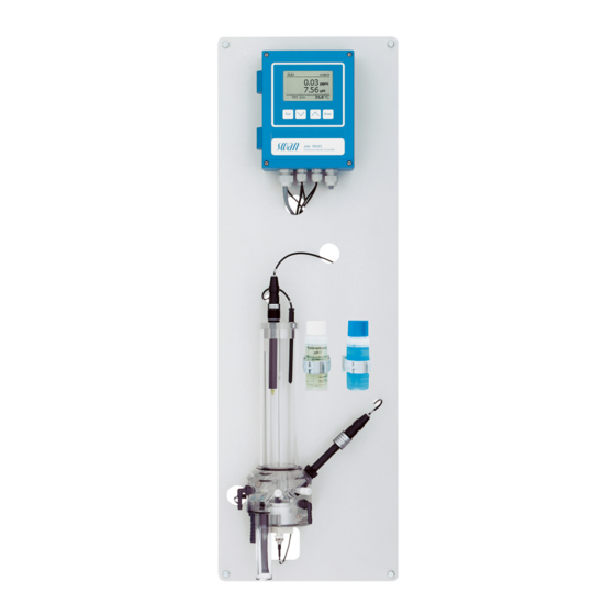
AMI Trides Product Description 2.3. Instrument Overview Panel Grab sample valve Transmitter Grab sample outlet pH/Redox electrode Trides sensor Temperature sensor Filter Calibration solution pH 7 Sample outlet Sample inlet Calibration solution pH9 Constant head Hall-effect sensor Reference electrode Flow cell block Flow regulating valve A-96.250.111 / 161120... -
Page 20: Installation
AMI Trides Installation Installation 3.1. Installation Checklist On-site AC variant: 100–240 VAC ( 10%), 50/60 Hz ( 5%) requirements DC variant: 10–36 VDC Power consumption: 35 VA maximum. Protective earth connection required. Sample line with sufficient sample flow and pressure (see Instrument Specification, p. -
Page 21: Mounting Of Instrument Panel
AMI Trides Installation 3.2. Mounting of Instrument Panel The first part of this chapter describes the preparing and placing of the system for use. The instrument must only be installed by trained personnel. Mount the instrument in vertical position. -
Page 22: Install The Reference Electrode
AMI Trides Installation 3.4. Install the Reference Electrode The reference electrode is delivered separately and protected with a water-filled protective cap. The connector is fixed to the panel with an adhesive tape and already connected to the front end PCB in the AMI transmitter. -
Page 23: Install The Temperature Sensor
AMI Trides Installation 3.5. Install the Temperature Sensor The temperature sensor is fixed to the panel with an adhesive tape and already connected to the front end PCB in the AMI transmitter. Temperature sensor Constant head cover Constant head To install the temperature sensor proceed as follows: 1 Remove the temperature sensor [A] from the panel. -
Page 24: Install The Ph Or Redox Electrode Into The Flow Cell
AMI Trides Installation 3.6.1 Install the pH or Redox Electrode into the Flow Cell Connector pH /Redox electrode Constant head cover Sensor cap Constant head 1 Switch the instrument off. 2 Remove the cap [D] from the pH/redox electrode [B]. -
Page 25: Connect The Ph Electrode To The Transmitter
AMI Trides Installation 3.6.2 Connect the pH Electrode to the Transmitter WARNING Risk of electrical shock Installation and maintenance of electrical parts must be per- formed by professionals. Always turn off power before manipulat- ing electric parts. 1 Open the transmitter housing 2 Feed the cable of the electrode through one of the PG 7 cable glands [C] into the transmitter housing. -
Page 26: Firmware Settings For Ph/Redox Electrode
AMI Trides Installation 3.6.3 Firmware Settings for pH/Redox Electrode After the pH/Redox electrode has been installed according to the previous instructions activate the pH/Redox electrode in the menu installation as follows: 1 Navigate to Menu <Installation>, Sensors 5.1.1 <Sensors> Type of Electrode 2 Select pH Electrode. -
Page 27: Electrical Connections
AMI Trides Installation 3.7. Electrical Connections WARNING Electrical hazard. Always turn off power before manipulating electric parts. Grounding requirements: Only operate the instrument from a power outlet which has a ground connection. Make sure the power specification of the instrument corre- sponds to the power on site. - Page 28 AMI Trides Installation WARNING External Voltage. External supplied devices connected to relay 1 or 2 or to the alarm relay can cause electrical shocks Make sure that the devices connected to the following contacts are disconnected from the power before resuming installation.
-
Page 29: Connection Diagram
AMI Trides Installation 3.7.1 Connection Diagram CAUTION Use only the terminals shown in this diagram, and only for the mentioned purpose. Use of any other terminals will cause short circuits with possible corresponding consequences to material and personnel. A-96.250.111 / 161120... -
Page 30: Power Supply
Mains cable to comply with standards IEC 60227 or IEC requirements 60245; flammable rating FV1 Mains equipped with an external switch or circuit-breaker – near the instrument – easily accessible to the operator – marked as interrupter for AMI Trides A-96.250.111 / 161120... -
Page 31: Relay Contacts
AMI Trides Installation 3.8. Relay Contacts 3.8.1 Input Note: Use only potential-free (dry) contacts. The total resistance (sum of cable resistance and resistance of the relay contact) must be less than 50 Ω. Terminals 16/42 For programming see Input 5.3.4, p. -
Page 32: Relay 1 And 2
AMI Trides Installation 3.8.3 Relay 1 and 2 Note: Max. load 1 A/250 VAC Relay 1 and 2 can be configured as normally open or as normally closed. Standard for both relays is normally open. To configure a Re- lay as normally closed, set the jumper in the upper position. - Page 33 AMI Trides Installation CAUTION Risk of damage of the relays in the AMI Transmitter due to heavy inductive load. Heavy inductive or directly controlled loads (solenoid valves, dos- ing pumps) may destroy the relay contacts. To switch inductive loads > 0.1 A use an AMI relay box avail- able as an option or suitable external power relays.
-
Page 34: Signal Outputs
AMI Trides Installation 3.9. Signal Outputs 3.9.1 Signal Output 1 and 2 (current outputs) Note: Max. burden 510 Ω If signals are sent to two different receivers, use signal isolator (loop isolator). Signal output 1: Terminals 14 (+) and 13 (-) -
Page 35: Signal Output 3
AMI Trides Installation 3.10.1 Signal Output 3 Terminals 38 (+) and 37 (-). Requires the additional board for the third signal output 0/4–20 mA. The third signal output can be operated as a current source or as a current sink (switchable via switch [A]). For detailed information see the corresponding installation instruction. -
Page 36: Hart Interface
AMI Trides Installation 3.10.3 HART Interface Terminals 38 (+) and 37 (-). The HART interface PCB allows for communication via the HART protocol. For detailed information, consult the HART manual. HART Interface PCB 3.10.4 USB Interface The USB Interface is used to store Logger data and for Firmware upload. -
Page 37: Instrument Setup
AMI Trides Instrument Setup Instrument Setup After the analyzer is installed according to the previous instructions, connect the power cord. Do not switch on power yet! 4.1. Establish sample flow 1 Open the flow regulating valve. 2 Wait until the constant head is filled, and the rotor of the Trides sensor starts rotating. -
Page 38: Correction Of Trides Sensor
24 h running in. A zero point calibration is not necessary. The standard method to correct the AMI Trides sensor is the DPD photometric method. Use a high quality photometer (e.g. Swan Che- matest), to determine the reference value. Perform 3 manual mea- surements and calculate the average value. -
Page 39: Operation
AMI Trides Operation Operation 5.1. Keys Exit Enter to exit a menu or command (rejecting any changes) to move back to the previous menu level to move DOWN in a menu list and to decrease digits to move UP in a menu list and to increase digits... -
Page 40: Display
AMI Trides Operation 5.2. Display 15:20:18 0.45 360 rpm 24.8°C A RUN normal operation HOLD input closed or cal delay: Instrument on hold (shows status of signal outputs). input closed: control/limit is interrupted (shows status of signal outputs). ERROR Error... -
Page 41: Software Structure
AMI Trides Operation 5.3. Software Structure Main Menu Messages Diagnostics Maintenance Operation Installation Menu 1 Messages Messages Reveals pending errors as well as an event history Pending Errors (time and state of events that have occurred at an Message List earlier point of time). -
Page 42: Changing Parameters And Values
AMI Trides Operation 5.4. Changing Parameters and values Changing The following example shows how to change the logger interval: parameters 1 Select the parameter you want to Sensors Logger 5.1.2 4.4.1 change. Sensor type FOME Log interval 30 min 2 Press [Enter] Disinf. -
Page 43: Maintenance
Daily up to Check sample supply for dirt. every 2 Clean all filters and strainers, if necessary. weeks Clean AMI Trides protection filter, if necessary. Check sample flow. Weekly pH/Redox option: Perform Process pH/Redox. (some Determine disinfectant value by manual DPD analysis and, if countries necessary, perform Process Trides. - Page 44 Daily up to Check sample supply for dirt. every 2 Clean all filters and strainers, if necessary. weeks Clean AMI Trides protection filter, if necessary. Check sample flow. Weekly pH option: Perform Process pH. (some Determine disinfectant value by manual DPD analysis and, if countries necessary, perform <Process Trides>.
-
Page 45: Cleaning Of Trides Protective Filter
AMI Trides Maintenance 6.2. Cleaning of Trides protective filter Flow regulating valve Filter Filter vessel If the protection filter shows deposits, proceed as follows: 1 Close the flow regulating valve [A]. 2 Close the sample main tap before the filter. -
Page 46: Cleaning Of Trides Sensor
AMI Trides Maintenance 6.3. Cleaning of Trides sensor Flow regulating valve Orifices Threaded bolt Trides sensor Rotor BNC connector O-Ring Knurled nut 1 Close the flow regulating vale [A]. 2 Wait until rotor [C] stops and DIS reading is 0 ppm. - Page 47 AMI Trides Maintenance 6 Hold the Trides sensor [F] with one hand while unscrewing and removing the 2 knurled nut. 7 Remove the Trides sensor from the flow cell. Take care not to spill the sample remaining in the sensor.
-
Page 48: Cleaning Of Reference Electrode
AMI Trides Maintenance 6.4. Cleaning of Reference Electrode Reference electrode Washer Union screw O-Ring 1 Close the flow regulating vale. 2 Loosen the union screw [B] 3 Pull the reference electrode out. 4 Wipe sensor tip cautiously with a soft tissue. If necessary use al- cohol to remove oily deposits. -
Page 49: Cleaning Of Ph Electrode
AMI Trides Maintenance 6.5. Cleaning of pH Electrode pH electrode Constant head cover Constant head Clean 1 Pull the pH electrode [A] out of the constant head. pH Electrode 2 If necessary wipe the electrode shaft and the green tip cautiously with a soft, clean, and damp paper tissue. -
Page 50: Cleaning Of Flow Cell
AMI Trides Maintenance 6.6. Cleaning of Flow Cell Constant head cover Constant head tube Overflow tube to waste Overflow tube to sensor O-ring Flow cell block Grab sample tap Grab sample outlet Filter Filter vessel Sample outlet Sample Inlet Flow regulating... - Page 51 AMI Trides Maintenance Disassemble 1 Switch off the instrument. the flow cell 2 Stop the sample flow at the main tap before the sample inlet. 3 Open the grab sample tap [G] to empty the flow cell. 4 Remove all sensors.
-
Page 52: Calibration Of Trides Sensor
6.7. Calibration of Trides Sensor The following description of the calibration procedure assumes that the AMI Trides is equipped with a pH electrode. In case your AMI Tri- des has no pH electrode, skip the pH calibration. 6.7.1 Process pH The process calibration is based on a comparative measurement of the on-line instrument with a calibrated comparative electrode. -
Page 53: Standard Ph
AMI Trides Maintenance 5 Enter the process value measured Process pH 3.1.1.1 with the calibrated comparative Current Value 7.78 pH electrode. Offset -8.15 mV Use the [ ] or [ ] keys to increase or decrease the Process Value 7.60 pH... -
Page 54: Standard Redox
Use a high quality photometer to determine the reference value, e.g. Swan Chematest. Take the sample from the grab sample outlet of the AMI Trides and perform 3 manual measurements. Then calculate the average value and use it to for comparison. - Page 55 AMI Trides Maintenance 1 Select Process Trides Calibration 3.1.1 2 Press [Enter] Process pH Standard pH Zero Trides Process Trides The following values are displayed: Process Trides 3.1.4.1 Current value Current Value 0.30 ppm Slope Slope x µA ...
-
Page 56: Longer Stop Of Operation
AMI Trides Maintenance 6.8. Longer Stop of Operation Do not switch the instrument off if your operation is suspended for less than a week. Power consumption is very low, and the sensors remain ready for use. If water hardness is very high, calcium may precipitate. -
Page 57: Troubleshooting
AMI Trides Troubleshooting Troubleshooting This chapter provides some hints to make trouble shooting easier. For any detailed information how to replace or clean parts please see chapter Maintenance. Attention: The sample for the manual measurement (with DPD!) must be taken directly from the flow cell! If you need further help please contact your dealer. -
Page 58: Troubleshooting List
AMI Trides Troubleshooting 7.2. Troubleshooting List Problem Possible Reason Insufficient or no sample flow. “No sample flow or Current Value too pH too high The process value used for a calibration low” during should be at least 0.15 ppm at a pH 7. - Page 59 AMI Trides Troubleshooting Disinfectant free chlorine: Check pH Trides display value of sample, check programmed/ higher than man- displayed value. ual measurement Sand (or other abrasive material) in the sample. Stop sand addition remove remaining sand and wait until the sensor signal has come down.
-
Page 60: Error List
AMI Trides Troubleshooting 7.3. Error List Error Non-fatal Error. Indicates an alarm if a programmed value is exceed- Such Errors are marked E0xx (bold and black). Fatal Error (blinking symbol) Control of dosing devices is interrupted. The indicated measured values are possibly incorrect. - Page 61 AMI Trides Troubleshooting Error Description Corrective action – check process E001 DIS. Alarm high – check programmed value, see 5.3.1.1, p. 77 – check process E002 DIS. Alarm low – check programmed value, see 5.3.1.1, p. 77 – check process...
- Page 62 AMI Trides Troubleshooting Error Description Corrective action – check case/environment temperature E014 Case Temp. low – check programmed value, see 5.3.1.6, p. 79 – Check if conductivity value of sample is E015 TRIDES Reference > 5 µS/cm. – Calculate: actual Trides signal / average value 3 DPD meas.
-
Page 63: Replacing Fuses
AMI Trides Troubleshooting 7.4. Replacing Fuses WARNING External Voltage. External supplied devices connected to relay 1 or 2 or to the alarm relay can cause electrical shocks Make sure that the devices connected to the following con- tacts are disconnected from the power before resuming in- stallation. -
Page 64: Program Overview
AMI Trides Program Overview Program Overview For explanations about each parameter of the menus see Program List and Explanations, p. 69 Menu 1 Messages informs about pending errors and mainte- nance tasks and shows the error history. Password protection possible. -
Page 65: Maintenance (Main Menu 3)
AMI Trides Program Overview Sensors Trides Sensor 2.2.1* * Menu numbers Current Value ppm 2.2.1* (Raw value 1) µA (Raw value 2) µA Ref. Voltage mV Cal. History 2.2.1.5.1* Number 2.2.1.5* Date, Time Offset Slope Electrode Measuring value 2.2.2 Raw value Cal History 2.2.2.3*... -
Page 66: Operation (Main Menu 4)
AMI Trides Program Overview 3.1.4 * Menu numbers Offset Process Value Simulation 3.3.1* Alarm Relay 3.3* Relay 1 3.3.2* 3.3.3* Relay 2 3.3.4* Signal Output 1 3.3.5* Signal Output 2 Set Time (Date), (Time) 3.4* 8.4. Operation (Main Menu 4) Sensors 4.10.1*... -
Page 67: Installation (Main Menu 5)
AMI Trides Program Overview 8.5. Installation (Main Menu 5) Sensors Type of Electrodes 5.1.1* * Menu numbers 5.1* 5.1.2* pH Electrodes 5.1.3* Disinf. 5.1.4* Dimension Standards 5.1.5.1* Standard 1 5.1.5* Standard 2 5.1.5.2* Signal Outputs Signal Output 1/2 5.2.1.1 - 5.2.2.1* Parameter 5.2*... - Page 68 AMI Trides Program Overview 5.3.2.400/ * Menu numbers Hysteresis 5.3.3.400* 5.3.2.50/ 5.3.3.50* Delay Input 5.3.4.1* Active 5.3.4* Signal Outputs 5.3.4.2* 5.3.4.3* Output/Control 5.3.4.4* Fault 5.3.4.5* Delay Miscellaneous 5.4.1* Language 5.4* Set defaults 5.4.2* Load Firmware 5.4.3* Password 5.4.4.1* Messages 5.4.4* 5.4.4.2*...
-
Page 69: Program List And Explanations
AMI Trides Program List and Explanations Program List and Explanations 1 Messages 1.1 Pending Errors 1.1.5 Provides the list of active errors with their status (active, acknowl- edged). If an active error is acknowledged, the alarm relay is active again. Cleared errors are moved to the Message list. -
Page 70: Maintenance
AMI Trides Program List and Explanations 2.3 Sample 2.3.1 Sample ID: Shows the identification assigned to a sample. This iden- tification is defined by the user to identify the location of the sample. Temperature: Shows the current temperature in °C and NT5K in Ohm. -
Page 71: Operation
AMI Trides Program List and Explanations Press the [Enter] key. Change the value or state of the selected item with the [ ] or ] key. Press the [Enter] key. The value is simulated by the relay/signal output. Active or inactive... -
Page 72: Installation
AMI Trides Program List and Explanations 4.4.1 Log Interval: Select a convenient log interval. Consult the table be- low to estimate the max logging time. When the logging buffer is full, the oldest data record is erased to make room for the newest one (circular buffer). - Page 73 AMI Trides Program List and Explanations 5.2.1 and 5.2.2 Signal Output 1 and 2: Assign process value, the current loop range and a function to each signal output. 5.2.1.1 Parameter: Assign one of the process values to the signal output.
- Page 74 AMI Trides Program List and Explanations [mA] 0 / 4 1’000 10’000 X Measured value (logarithmic) 5.2.1.40 Scaling: Enter beginning and end point (Range low & high) of the linear or logarithmic scale. In addition, the midpoint for the bilinear scale.
- Page 75 AMI Trides Program List and Explanations As control Signal outputs can be used for driving control units. We distinguish different kinds of controls: output P-controller: The controller action is proportional to the devia- tion from the setpoint. The controller is characterized by the P- Band.
- Page 76 AMI Trides Program List and Explanations Control upwards or downwards. Setpoint: User defined precess value for the selected parameter. P-Band: Range below (upwards control) or above (downwards con- trol) the set-point, within which the dosing intensity is reduced from 100% to 0% to reach the set-point without overshooting.
- Page 77 AMI Trides Program List and Explanations 5.3 Relay Contacts 5.3.1 Alarm Relay: The alarm relay is used as cumulative error indicator. Under normal operating conditions the contact is active. The contact is inactive at: Power loss Detection of system faults like defective sensors or electronic parts ...
- Page 78 AMI Trides Program List and Explanations 5.3.1.2.35 Hysteresis: Within the hyst. range, the relay does not switch. This prevents damage of relays contacts when the measured value fluctu- ates around the alarm value. Range. 0 –2 pH 5.3.1.2.45 Delay: Duration, the activation of the alarm relay is retarded after the measuring value has risen above/fallen below the programmed alarm.
- Page 79 AMI Trides Program List and Explanations 5.3.1.6 Case Temp. low: Set the alarm low value for temperature of electron- ics housing. If the value falls below the programmed value E014 is issued. Range: -10–20 °C 5.3.2 and 5.3.3 Relay 1 and 2: The contacts can be set as normally open or normal- ly closed with a jumper, see Relay 1 and 2, p.
- Page 80 AMI Trides Program List and Explanations 5.3.2.400 Hysteresis: within the hysteresis range, the relay does not switch. This prevents damage of relay contacts when the measured value fluctuates around the alarm value. Parameter Range 0.00–10 ppm pH/Redox 0–2 pH Temperature 0–120 °C...
- Page 81 AMI Trides Program List and Explanations 5.3.2.32.4 Control Parameters: Range for each Parameter same as 5.2.1.43, p. 76 Actuator = Frequency Examples of metering devices that are pulse frequency driven are the classic membrane pumps with a potential free triggering input.
- Page 82 AMI Trides Program List and Explanations 5.3.2.6 Signal Outputs: Select operating mode of the signal output: Signal outputs continue to issue the measured value. Cont.: Hold: Signal outputs hold the last valid measured value. Measurement is interrupted. Errors, except fatal errors, are not issued.
- Page 83 AMI Trides Program List and Explanations 5.3.2.342.2 Monday: Possible settings, on or off 5.3.2.342.8 Sunday: Possible settings, on or off 5.3.2.44 Run Time: see Interval 5.3.2.54 Delay: see Interval 5.3.2.6 Signal Outputs: see Interval 5.3.2.7 Output/Control: see Interval 5.3.2.1 Function = Fieldbus The relay will be switched via the Profibus input.
- Page 84 AMI Trides Program List and Explanations 5.3.4.4 Fault: No message is issued in pending error list and the alarm relay does not close when input is active. Message E024 is stored in the message list. Message E024 is issued and stored in the message Yes: list.
- Page 85 AMI Trides Program List and Explanations 5.5 Interface Select one of the following communication protocols. Depending on your selection, different parameters must be defined. 5.5.1 Protocol: Profibus 5.5.20 Device address: Range: 0–126 5.5.30 ID-Nr.: Range: Analyzer; Manufacturer; Multivariable 5.5.40 Local operation: Range: Enabled, Disabled 5.5.1...
-
Page 86: Material Safety Data Sheets
AMI Trides Material Safety Data sheets Material Safety Data sheets 10.1. Reagents Calibration Solution pH 4 Calibration Solution pH 7 Calibration Solution pH 9 Download The current Material Safety Data Sheets (MSDS) for the above listed Reagents are available for downloading at www.swan.ch. - Page 87 AMI Trides Default Values Default Values Operation: Sensors: Filter Time Const.:................ 30 s Hold after Cal.:................300 s Default pH................7.00 pH Relay Contacts Alarm Relay .............same as in Installation Relay 1/2 ............same as in Installation Input..............same as in Installation Logger: Logger Interval:...............
- Page 88 AMI Trides Default Values Sample Flow: Flow Alarm..................yes Alarm high: ................500 rpm Alarm low:................290 rpm Delay ....................5 s Sample Temp: Alarm High:................55 °C Alarm Low:................... 5 °C Case temp. high: ............... 65 °C Case temp. low:................0 °C Relay 1/2 Function:................limit upper...
- Page 89 AMI Trides Default Values Miscellaneous Language:................English Set default:..................no Load firmware: ................no Password: ..............for all modes 0000 Sample ID: ................- - - - - - - - Line break detection ............... no A-96.250.111 / 161120...
- Page 90 AMI Trides Index Index ......Alarm Relay Grab sample ....
- Page 91 AMI Trides Index ....Software ......
- Page 92 AMI Trides Notes Notes A-96.250.111 / 161120...
- Page 93 AMI Trides Notes A-96.250.111 / 161120...
- Page 94 Swan Products - Analytical Instruments for: Swan is represented worldwide by subsidiary companies and distributors and cooperates with independent representatives all over the world. For contact in- formation, please scan the QR code. Swan Analytical Instruments ∙ CH-8340 Hinwil www.swan.ch ∙ swan@swan.ch AMI Trides...
Need help?
Do you have a question about the AMI Trides and is the answer not in the manual?
Questions and answers