Advertisement
Quick Links
Advertisement

Subscribe to Our Youtube Channel
Related Manuals for Swan Analytical Instruments AMI Codes-II CC


Summary of Contents for Swan Analytical Instruments AMI Codes-II CC
- Page 1 A-96.250.581 / 181120 Operator’s Manual Firmware V6.21 and higher AMI Codes-II CC...
- Page 2 For any technical question, contact your nearest Swan representative, or the manufacturer: Swan Analytische Instrumente AG Studbachstrasse 13 8340 Hinwil Switzerland Internet: www.swan.ch E-mail: support@swan.ch Document Status AMI Codes-II CC Operator’s Manual Title: A-96.250.581 Revision Issue April 2010 June 2010 Aug. 2013 Update to Rev. 5.40, mainboard V2.4 June 2016 Update to Rev.
- Page 3 AMI Codes-II CC Table of Contents Safety Instructions ..........
- Page 4 AMI Codes-II CC Operation ........... . . 43 5.1.
- Page 5 AMI Codes-II CC Program List and Explanations ........84 1 Messages .
- Page 6 AMI Codes-II CC Safety Instructions AMI Codes-II CC–Operator’s Manual This document describes the main steps for instrument setup, opera- tion and maintenance. Safety Instructions General The instructions included in this section explain the potential risks associated with instrument operation and provide important safety practices designed to minimize these risks.
- Page 7 AMI Codes-II CC Safety Instructions 1.1. Warning Notices The symbols used for safety-related notices have the following meaning: DANGER Your life or physical wellbeing are in serious danger if such warn- ings are ignored. Follow the prevention instructions carefully.
- Page 8 AMI Codes-II CC Safety Instructions Warning Signs The warning signs in this manual have the following meaning: Electrical shock hazard Corrosive Harmful to health Flammable Warning general Attention general A-96.250.581 / 181120...
- Page 9 AMI Codes-II CC Safety Instructions 1.2. General Safety Regulations Legal The user is responsible for proper system operation. All precautions must be followed to ensure safe operation of the instrument. Requirements Spare Parts Use only official SWAN spare parts and disposables. If other parts are used during the normal warranty period, the manufacturer’s war-...
- Page 10 AMI Codes-II CC Safety Instructions 1.3. Restrictions for use The sample must not contain any particles, which may block the flow cell. Sufficient sample flow is coercive for the correct function of the instrument. If the sample contains only little disinfectant concentrations, or there is the danger of biological growth, we recommend to use the optional Cleaning module from Swan.
- Page 11 AMI Codes-II CC Product Description Product Description Application The AMI Codes-II CC is a complete monitoring system for the auto- matic, continuous measurement and dosing control of chlorine Range based on the DPD colorimetric method APHA 4500 Cl-G and on EN ISO 7393-2.
- Page 12 AMI Codes-II CC Product Description Alarm Relay One potential free contact. Alternatively: Open during normal operation, closed on error and loss of power. Closed during normal operation, open on error and loss of power. Summary alarm indication for programmable alarm values and in- strument faults.
- Page 13 AMI Codes-II CC Product Description Glossary Abbreviations used for the measured chlorine forms: Abbr. Term Comment Free available chlorine Immediate reaction with DPD (includes cyanuric acid fractions) Total chlorine 1 Immediate reaction of DPD + KJ (mainly monochloramine) Total chlorine 2 Reaction with DPD + KJ after 2 min.
- Page 14 AMI Codes-II CC Product Description Fluidics The sample flows through the sample inlet [R] and the inlet filter [H] into the constant head [A]. Adjust the flow regulating valve [F] so that always a small part of the sample flows through the overflow tube [B] into the constant head drain [Q].
- Page 15 AMI Codes-II CC Product Description Total chlorine 1 After the measurement of free available chlorine is finished the sole- noid valve [G] is energized for a short time and reagent [O] is added to determine total chlorine 1. Total chlorine 2 To ensure the necessary reaction time of 2 min.
- Page 16 AMI Codes-II CC Product Description General Two different types of measurements are distinguished: Free available chlorine (fac) measurement Overall measurement including free available chlorine (fac), to- tal chlorine 1 (tc1) and total chlorine 2 (tc2). The Interval fac and the Interval tc2 can be set individually: ...
- Page 17 AMI Codes-II CC Product Description tc 1 tc 2 Reaction time for measuring tc 2 Total chlorine 1 Flush time Total chlorine 2 Overall measurement time OXYCON ON-LINE DPD Flush time end OXYCON ON-LINE Buffer fac measurement OXYCON ON-LINE KI...
- Page 18 AMI Codes-II CC Product Description 2.1. Instrument Specification Power Supply AC variant: 100–240 VAC (± 10%) 50/60 Hz (± 5%) DC variant 10–36 VDC Power consumption: max. 35 VA Transmitter Housing: aluminum, with a protection degree of specifications IP 66 / NEMA 4X Ambient temperature: −10 to +50 °C...
- Page 19 AMI Codes-II CC Product Description Dimensions Panel: Dimensions: 400x850x200 mm Screws: 5 mm or 6 mm diameter Weight: 12.0 kg without reagents and sample water 17.0 kg with reagents and sample water 400 mm / 15.75" 374 mm / 14.72"...
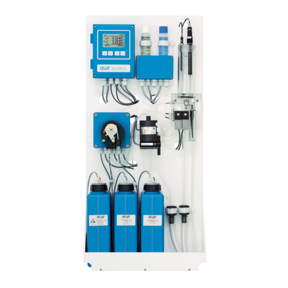
- Page 20 AMI Codes-II CC Product Description 2.2. Instrument Overview Panel Flow regulating valve Transmitter Sample inlet Peristaltic pump Valve 1 (Photometer) Reagent Oxycon on-line DPD Valve 2 (KI dosing) Reagent Oxycon on-line Buffer Inlet filter Photometer Reagent Oxycon on-line KI Temperature sensor...
- Page 21 AMI Codes-II CC Installation Installation 3.1. Installation Check List On-site AC variant: 100–240 VAC ( 10%), 50/60 Hz ( 5%) requirements DC variant: 10–36 VDC Power consumption: 35 VA maximum. Protective earth connection required. Sample line with sufficient sample flow and pressure (see Instrument Specification, p.
- Page 22 AMI Codes-II CC Installation Process Make 3 manual measurements. Use a high quality photometer, e.g. calibration Chematest from Swan. Calculate average value and compare this value to the value, indicated by the AMI. If necessary, correct the value. The zero point is done automatically before each measure- ment.
- Page 23 AMI Codes-II CC Installation 3.3. Connecting Sample and Waste 3.3.1 FEP Tube at Sample Inlet Use plastic tube (FEP, PA, or PE 6 x 8 mm) to connect the sample line. Mounting of Screw connection SERTO fitting Compression ferrule Knurled nut Flexible tube 3.3.2...
- Page 24 Installation of Flow Cell CAUTION Fragile Part Handle the constant head tube with care. To avoid damage during the transport, the constant head tube [C] of the AMI Codes-II CC is not installed. Constant head cover Overflow tube Constant head tube Gasket...
- Page 25 Install the pH Option 3.5.1 pH as Option ex works If the pH option was ordered with the AMI Codes-II CC, the pH sen- sor cable as well as the temperature sensor are already connected to the AMI transmitter. Connector cap...
- Page 26 AMI Codes-II CC Installation 3.5.2 pH Option as Retrofit Kit 2 Clamps with screws Frontend PCB pH sensor Temperature sensor Sensor cable Short overflow tube A-96.250.581 / 181120...
- Page 27 AMI Codes-II CC Installation WARNING Risk of electrical shock. Do not perform any work on electrical components if the transmit- ter is switched on. Failure to follow safety instructions can result in serious injury or death. 1 Screw the clamps for calibration solution onto the panel. Use the already drilled holes [A].
- Page 28 AMI Codes-II CC Installation Front end PCB pH sensor plug Temperature sensor plug A B C 7 Open the cover of the AMI transmitter housing. 8 Install the front end PCB. 9 Feed the cable of the pH sensor through one of the cable glands (see Cable thicknesses, p.
- Page 29 AMI Codes-II CC Installation 3.6. Electrical Connections WARNING Risk of electrical shock. Do not perform any work on electrical components if the transmit- ter is switched on. Failure to follow safety instructions can result in serious injury or death. Always turn off power before manipulating electric parts.
- Page 30 AMI Codes-II CC Installation WARNING External Voltage Externally supplied devices connected to relay 1 or 2 or to the alarm relay can cause electrical shocks Make sure that the devices connected to the following contacts are disconnected from the power before continuing installation.
- Page 31 AMI Codes-II CC Installation 3.6.1 Connection Diagram CAUTION Use only the terminals shown in this diagram, and only for the mentioned purpose. Use of any other terminals will cause short circuits with possible corresponding consequences to material and personnel. A-96.250.581 / 181120...
- Page 32 Mains cable to comply with standards IEC 60227 or IEC requirements 60245; flammable rating FV1 Mains equipped with an external switch or circuit-breaker – near the instrument – easily accessible to the operator – marked as interrupter for AMI Codes-II CC A-96.250.581 / 181120...
- Page 33 AMI Codes-II CC Installation 3.7. Input Note: Use only potential-free (dry) contacts. The total resistance (sum of cable resistance and resistance of the relay contact) must be less than 50 Ω. Terminals 30 and 31 For programming see chap. 9, menu Installation, 5.3.4, p.
- Page 34 AMI Codes-II CC Installation Note: Some error codes and the instrument status may influence the status of the relays described below. Relay Jumper config. Terminals pos. Description Relay configuration Normally 6/7: Relay 1 Inactive (opened) during Open 8/9: Relay 2 normal operation and loss of power.
- Page 35 AMI Codes-II CC Installation CAUTION Risk of damage of the relays in the AMI Transmitter due to heavy inductive load. Heavy inductive or directly controlled loads (solenoid valves, dos- ing pumps) may destroy the relay contacts. To switch inductive loads > 0.1 A use an AMI relay box avail- able as an option or suitable external power relays.
- Page 36 AMI Codes-II CC Installation 3.9. Signal Outputs 3.9.1 Signal Output 1 and 2 (current outputs) Note: Max. burden 510 Ω If signals are sent to two different receivers, use signal isolator (loop isolator). Signal output 1: Terminals 14 (+) and 13 (-)
- Page 37 AMI Codes-II CC Installation 3.10.1 Signal Output 3 Terminals 38 (+) and 37 (-). Requires the additional board for the third signal output 0/4–20 mA. The third signal output can be operated as a current source or as a current sink (switchable via switch [A]). For detailed information see the corresponding installation instruction.
- Page 38 AMI Codes-II CC Installation 3.10.3 HART Interface Terminals 38 (+) and 37 (-). The HART interface PCB allows for communication via the HART protocol. For detailed information, consult the HART manual. HART Interface PCB 3.10.4 USB Interface The USB Interface is used to store Logger data and for Firmware up- load.
- Page 39 AMI Codes-II CC Instrument Setup Instrument Setup After installation according to checklist proceed as following: 4.1. Prepare Reagents 1 Prepare reagents. See Refill or replace Reagents, p. 2 Insert the suction lances into the containers. 4.2. Peristaltic Pump The instrument is delivered with opened occlusion frames.
- Page 40 AMI Codes-II CC Instrument Setup 4.3. Establish Sample Flow WARNING Water pollution The drain of the photometer outlet contains DPD. At no means recirculate it into the water system. Cover Constant head tube Flow cell block Flow regulating valve...
- Page 41 AMI Codes-II CC Instrument Setup 4.4. Fill or Flush Reagent System Fill or flush the reagent tubing: upon the initial instrument setup, after refilling the reagent containers, before a system shut-down to flush the system with demineral- ized water until no more reagent is left in the system.
- Page 42 AMI Codes-II CC Instrument Setup 4.6. Calibration 1 Calibrate pH sensor (if pH option is installed). Standard pH, p. 2 Perform process calibration. Process Calibration of tc & fc, p. 54 If ordered: The instrument should be operating for 1 h before performing a pH calibration.
- Page 43 AMI Codes-II CC Operation Operation 5.1. Keys Exit Enter to exit a menu or command (rejecting any changes) to move back to the previous menu level to move DOWN in a menu list and to decrease digits to move UP in a menu list and to increase digits...
- Page 44 AMI Codes-II CC Operation 5.2. Display 12:56:02 0.22 12:55:35 12:52:40 0.26 0.04 12:52:40 47 B/s 26.8 °C A RUN normal operation HOLD input closed or cal delay: Instrument on hold (shows sta- tus of signal outputs). input closed: control/limit is interrupted (shows status of signal outputs).
- Page 45 AMI Codes-II CC Operation 5.3. Software Structure Main Menu Messages Diagnostics Maintenance Operation Installation Menu Messages 1 Messages Reveals pending errors as well as an event history Reagent Status (time and state of events that have occurred at an Pending Errors earlier point of time).
- Page 46 AMI Codes-II CC Operation 5.4. Changing Parameters and values Changing The following example shows how to change the logger interval: parameters 1 Select the parameter you want to Sensors Logger 5.1.2 4.4.1 change. Sensor type FOME Log interval 30 min 2 Press [Enter] Disinf.
- Page 47 AMI Codes-II CC Maintenance Maintenance 6.1. Maintenance Schedule Daily (dirty water) up Check sample supply for dirt. to every 2 weeks Clean all filters and strainers, if necessary. (clean water) Clean AMI Codes protection filter, if necessary. Check sample flow (see also Troubleshooting, p.
- Page 48 AMI Codes-II CC Maintenance 6.2. Stop of Operation for Maintenance 1 Put the suction lances into a bucket with clean water. 2 Start <Fill system>. The reagent tubes are flushed with water. 3 Remove the suction lances from the water.
- Page 49 AMI Codes-II CC Maintenance 6.3. Refill or replace Reagents The liquid level in the containers 2 and 3 is monitored. The following messages are displayed: Container almost Maintenance E065 - Reagents low and the empty remaining reagent volume in % (starting at 17 % = 340 ml).
- Page 50 AMI Codes-II CC Maintenance Oxycon On-line DPD WARNING Severe eye irritation and severe skin irritation. Concentrated Oxycon On-line DPD contains more than 10% min- eral acids. Do not swallow. Avoid any contact with eyes and skin. Wear protective goggles, ...
- Page 51 AMI Codes-II CC Maintenance Canister set up Suction lance without level detector (canister 1) Suction lance with level detector (canisters 2 and 3) Level detector 2 L mark Canister 1: Oxycon on-line DPD Canister 2: Oxycon on-line Buffer Canister 3: Oxycon...
- Page 52 AMI Codes-II CC Maintenance 7 Remove the screw cover and insert the suction lance [A] and tighten the screw cover. Prepare 1 Rinse the canister [F] labelled “OXYCON ON LINE Buffer” solu- tion with demineralized water. Oxycon On-line Buffer 2 Fill the canister up to the 2 liter mark [D] with demineralized wa- ter.
- Page 53 AMI Codes-II CC Maintenance 6.4. Verification The “Verification kit for AMI Photometer” is available as an accessory. An optical window with a precisely determined absorbance value is placed into the light beam of the photometer. The actual measured absorbance will be compared to the reference value labeled on each kit.
- Page 54 AMI Codes-II CC Maintenance 6.5. Calibration Process Note: Perform process calibration for free chlorine or total Calibration residual chlorine only if: of tc & fc • the sample concentration is close to the desired process value (stable value). • you are sure that the reagents are mixed completely and correctly.
- Page 55 AMI Codes-II CC Maintenance Process pH Use a Chematest photometer (or equivalent) to determine the sam- ple pH value. Insert the electrode through a hole in the constant head cover into the constant head. Note: Make sure your reference instrument is calibrated...
- Page 56 AMI Codes-II CC Maintenance Standard pH 1 Navigate to menu <Maintenance>/ Maintenance <Calibration>. Calibration Enter 2 Press [Enter]. Simulation Set Time 01.06.04 16:30:00 3 Remove the pH sensor from the Enter Fill System flow cell. Cleaning 4 Follow the instructions on the dis- Calibration play.
- Page 57 AMI Codes-II CC Maintenance 6.6. Cleaning the protective Filter Switch off the instrument according to instructions in Stop of Opera- tion for Maintenance, p. Flow cell block Flow regulating valve Filter shaft Filter Filter vessel Normally the filter in your sample supply line will retain most debris. If the filter shows deposits, proceed as follows: 1 Close the main tap of the sample inlet.
- Page 58 AMI Codes-II CC Maintenance 6.7. Cleaning the Photometer Clean the photometer after indication by alarm (E020, FOME dirty). Switch off the instrument according to instructions in Stop of Opera- tion for Maintenance, p. Material Small brush. Procedure Flow regulating valve...
- Page 59 AMI Codes-II CC Maintenance 6.8. Cleaning the Flow Cell CAUTION Acrylic glass parts are fragile and scratch-sensitive. Possible damage of acrylic glass parts due to scrubbing materials. Never use organic solvents or scrubbing materials to clean acrylic glass parts.
- Page 60 AMI Codes-II CC Maintenance Cleaning 1 Switch off the instrument according to instructions in Stop of Op- eration for Maintenance, p. 2 Remove the constant head cover [A]. 3 Remove the constant head tube [C] from the flow cell block.
- Page 61 AMI Codes-II CC Maintenance 6.8.2 Assemble the Flow Cell Constant head cover Overflow tube Constant head tube Gasket Flow cell block Level 1 Replace the gasket [D] before reassembling the flow cell. Note: A film of teflon paste (e.g. Fomblin from Solvay Solexis) on the gaskets improves tightness and life time.
- Page 62 AMI Codes-II CC Maintenance 6.9. Maintenance of pH sensor Connector pH sensor shaft Flow cell cover Flow cell Clean 1 Remove the pH sensor [B] from the flow cell. pH sensor 2 Unscrew and remove the connector [A] from the pH sensor.
- Page 63 AMI Codes-II CC Maintenance 6.10. Tube Replacement 6.10.1 Replace the Pump Tubes The pump tube [D] of the peristaltic pump is exposed to a minimal wear. It is therefore recommended to exchange the pump tube annu- ally. CAUTION Pollution of reagents possible.
- Page 64 AMI Codes-II CC Maintenance Dismount The pump tube can easily be dismounted and mounted. Proceed as follows: pump tubes Pump housing Occlusion frame open Rotor Pump tube Pump inlet Pump outlet 1 Switch off the instrument according to instructions in Stop of Op- eration for Maintenance, p.
- Page 65 AMI Codes-II CC Maintenance 6.10.2 Replace the Reagent Tubes Tube numbering Level from Pump outlet rear frame Flow cell block, connection 1 see Flow cell block side view Q Pump outlet middle frame Flow cell block, connection 2 see Flow cell block side view Q...
- Page 66 AMI Codes-II CC Maintenance 6.11. Cleaning the solenoid valve Disassemble The solenoid valves are mounted at the bottom of the flow cell block. The solenoid valve should be disassembled if it does not switch any- the solenoid more or if it is clogged.
- Page 67 AMI Codes-II CC Maintenance 4 Loosen the fixing screws of the valve body with a 2.5 mm Allen key (D). Note: The O-rings inside the valve body may stick on the flow cell and fall down if the valve body is removed.
- Page 68 AMI Codes-II CC Maintenance 6.12. Longer Stop of Operation 1 Put the suction lances into a bucket with clean water. 2 Start <Fill system>. The reagent tubes are flushed with water. 3 Remove the suction lances from the water.
- Page 69 AMI Codes-II CC Troubleshooting Troubleshooting This chapter provides some hints to make troubleshooting easier. For any detailed information how to handle or clean parts please see Maintenance, p. 47. For any detailed information how to program the instrument please see Program List and Explanations, p.
- Page 70 AMI Codes-II CC Troubleshooting 7.2. Calibration Errors 7.2.1 Process calibration tc or fc Possible error Slope error: message Possible cause Corrective Action Wrong manual Repeat the manual measurement. measurement. Use fresh reagents. Wrong reagent mixture Make a correct mixture.
- Page 71 AMI Codes-II CC Troubleshooting 7.3. Error List Error Non-fatal Error. Indicates an alarm if a programmed value is exceed- Such Errors are marked E0xx (bold and black). Fatal Error (blinking symbol) Control of dosing devices is interrupted. The indicated measured values are possibly incorrect.
- Page 72 AMI Codes-II CC Troubleshooting Error Description Corrective action – check process E001 Alarm high fac (Free available chlorine) – check programmed value 5.3.1.1.1.1, p. – check process E002 Alarm low fac (Free available chlorine) – check programmed value 5.3.1.1.1.26, p. 96 –...
- Page 73 AMI Codes-II CC Troubleshooting Error Description Corrective action – check wiring of temperature sensor, see E011 Temp. shorted Connection Diagram, p. 31 – check temperature sensor – check wiring of temperature sensor, see E012 Temp. disconnected Connection Diagram, p. 31 –...
- Page 74 AMI Codes-II CC Troubleshooting Error Description Corrective action – refill cleaning solution, see Refill or E023 Cleaning Solution replace Reagents, p. 49 – See If Fault Yes is programmed in Menu E024 Input active 5.3.4, p. 103 – call service...
- Page 75 AMI Codes-II CC Troubleshooting 7.4. Opening the peristaltic pump housing For some electrical connections (e.g. when replacing suction lanc- es), it is necessary to open the housing of the peristaltic pump. To do this, proceed as follows: 1 Switch off the analyzer according to Stop of Operation for Mainte- nance, p.
- Page 76 AMI Codes-II CC Troubleshooting 7.5. Replacing Fuses WARNING External Voltage. Externally supplied devices connected to relay 1 or 2 or to the alarm relay can cause electrical shocks. Make sure that the devices connected to the following contacts are disconnected from the power before resuming installation.
- Page 77 AMI Codes-II CC Program Overview Program Overview For explanations about each parameter of the menus see Program List and Explanations, p. Menu 1 Messages informs about pending errors and mainte- nance tasks and shows the error history. Password protection possible.
- Page 78 AMI Codes-II CC Program Overview 8.2. Diagnostics (Main Menu 2) Identification * Menu numbers Designation AMI Codes-II CC 2.1* Version V6.21 - 07/17 Peripherals 2.1.3.1* PeriClip 1 / 1.03 2.1.3* PeriClip 2 only with cleaning module Factory Test 2.1.4.1* Instrument 2.1.4*...
- Page 79 AMI Codes-II CC Program Overview 8.3. Maintenance (Main Menu 3) Calibration Free av. chlorine * Menu numbers Current Value 3.1* 3.1.1* Factor 3.1.1.4* Process Value Total chlorine 2 Current Value 3.1.2* Factor 3.1.2.4* Process Value Process pH Current Value 3.1.3* Offset 3.1.3.4*...
- Page 80 AMI Codes-II CC Program Overview 8.4. Operation (Main Menu 4) Sensors 4.1.1* * Menu numbers Filter Time Const. 4.1* Hold after Cal. 4.1.2* 4.1.3* Interval fac 4.1.4* Interval tc2 4.1.5* Default pH Relay Contacts Alarm Relay Free av. chlorine 4.2.1.1.1* Alarm High 4.2*...
- Page 81 AMI Codes-II CC Program Overview Logger 4.3.1* Log Interval 4.3* 4.3.2* Clear Logger 4.3.3* Eject USB Stick (If USB interface is installed) Display Screen 1 Row 1 4.4.1.1* 4.4* 4.4.1* 4.4.1.2* Row 2 4.4.1.3* Row 3 Screen 2 4.4.2.1* Row 1 4.4.2*...
- Page 82 AMI Codes-II CC Program Overview 8.5. Installation (Main Menu 5) Sensors 5.1.1* * Menu numbers Dimension 5.1* Interpolation 5.1.2* 5.1.3* Ref. Verification Standards 5.1.4.1* Standard 1 only with pH option 5.1.4* 5.1.4.2* Standard 2 5.1.5 Cleaning only with Cleaning Module Signal Outputs Signal Output 1 &...
- Page 83 AMI Codes-II CC Program Overview Relay 1 & 2 5.3.2.1 & 5.3.3.1* Function 5.3.2* & 5.3.3* 5.3.2.x & 5.3.3.x* Parameter 5.3.2.x & 5.3.3.x* Setpoint Hysteresis 5.3.2.x & 5.3.3.x* 5.3.2.x & 5.3.3.x* Delay Input 5.3.4.1* Active 5.3.4* 5.3.4.2* Signal Outputs 5.3.4.3*...
- Page 84 AMI Codes-II CC Program List and Explanations Program List and Explanations 1 Messages 1.1 Reagent Status 1.1.1 DPD/Buffer: Shows the fill level of the DPD/Buffer. Potassium Iodide: Shows the fill level of the Potassium Iodide. Cleaning solution: Shows the fill level of the Cleaning solution.
- Page 85 AMI Codes-II CC Program List and Explanations 2.2.1.4 Cal. History: Shows the diagnostic values of the last calibrations. Number: Counter for the calibrations Date, Time: Date and time assigned to a number. Factor fc: Factor fc is the multiplier applied to the slope of the free chlorine calibration line.
- Page 86 AMI Codes-II CC Program List and Explanations 2.4 I/O State Shows current status of all in- and outputs. 2.4.1 & 2.4.2 Active or inactive Alarm Relay: Active or inactive Relay 1 & 2: Open or closed Input: Signal Output 1 & 2: Actual current in mA...
- Page 87 AMI Codes-II CC Program List and Explanations 3.3 Simulation To simulate a value or a relay state, select the alarm relay, relay 1 or 2 signal output 1 or 2 valve 1 or 2 with the [ ] or [ ] key.
- Page 88 AMI Codes-II CC Program List and Explanations 3.5.1.3 Delay: During cleaning plus the delay time, the status of the signal and control outputs is as set in 3.5.1.4 and 3.5.1.5. Range: 0–6000 s 3.5.1.4 Signal Outputs: Select the operation mode of the signal outputs during cleaning: Signal outputs continue to issue the measured value.
- Page 89 AMI Codes-II CC Program List and Explanations all modes 3.7.2 Fill Channel 11: Activates the cleaning pump and switches the valve to cleaning solution 1 (right canister). 3.7.3 Fill Channel 12: Activates the cleaning pump and switches the valve to cleaning solution 2 (left canister).
- Page 90 AMI Codes-II CC Program List and Explanations 4.3.1 Log Interval: Select a convenient log interval. Consult the table be- low to estimate the max logging time. When the login buffer is full, the oldest data record is erased to make room for the newest one.
- Page 91 AMI Codes-II CC Program List and Explanations 5 Installation 5.1 Sensors 5.1.1 Dimension: The measuring value can be displayed as ppm or mg /l 5.1.2 Interpolation: Yes: Calculates the average of the 2 last measuring values of free chlorine measurement. Use this mode to avoid high spikes in the control loop.
- Page 92 AMI Codes-II CC Program List and Explanations 5.2.1.3 Function: Define if the signal output is used to transmit a process val- ue or to drive a control unit. Available functions are: Linear, bilinear or logarithmic for process values. As process values, p. 92 ...
- Page 93 AMI Codes-II CC Program List and Explanations 5.2.1.40 Scaling: Enter beginning and end point (Range low & high) of the linear or logarithmic scale. In addition, the midpoint for the bilinear scale. Parameter Free av. chlorine 5.2.1.40.10 Range low: 0 –10 ppm or 0–10 mg/l 5.2.1.40.20...
- Page 94 AMI Codes-II CC Program List and Explanations As control out- Signal outputs can be used for driving control units. We distinguish different kinds of controls: P-controller: The controller action is proportional to the devia- tion from the setpoint. The controller is characterized by the P- Band.
- Page 95 AMI Codes-II CC Program List and Explanations Control upwards /downwards Setpoint: User-defined process value (Measured value or flow) P-Band: Range below (upwards control) or above (downwards control) the set-point, within the dosing intensity is reduced from 100% to 0% to reach the set-point without overshooting.
- Page 96 AMI Codes-II CC Program List and Explanations 5.3.2.32.31.4 Derivative time: The derivative time is the time till the ramp response of a single P-controller will reach the same value as it will be sudden- ly reached by a D-controller. Range: 0–9’000 Sec 5.3.2.32.31.5...
- Page 97 AMI Codes-II CC Program List and Explanations 5.3.1.1.1.46 Delay: Duration, the activation of the alarm relay is retarded after the measuring value has risen above/fallen below the programmed alarm. Range: 0.00–28‘800 Sec 5.3.1.1.2 Total chlorine 1 5.3.1.1.2.1 Alarm High: If the measured value rises above the alarm high value, the alarm relay is activated and E003 is displayed in the message list.
- Page 98 AMI Codes-II CC Program List and Explanations 5.3.1.4 Sample Flow: Define at which sample flow a flow alarm should be issued. 5.3.1.4.1 Flow Alarm: Program if the alarm relay should be activated if there is a flow alarm. Choose between yes or no. The flow alarm will always be indicated in the display, pending error list, saved in the message list and the logger.
- Page 99 AMI Codes-II CC Program List and Explanations 5.3.2 and 5.3.3 Relay 1 and 2: The contacts can be set as normally open or normal- ly closed with a jumper. See Relay 1 and 2, p. The function of relay contacts 1 or 2 are defined by the user.
- Page 100 AMI Codes-II CC Program List and Explanations 5.3.2.400 Hysteresis: within the hysteresis range, the relay does not switch. This prevents damage of relay contacts when the measured value fluctuates around the alarm value. Parameter Range Free av. chlorine 0–10 ppm Total chlorine 1 0–10 ppm...
- Page 101 AMI Codes-II CC Program List and Explanations 5.3.2.32.1 Actuator = Time proportional Examples of metering devices that are driven time proportional are solenoid valves, peristaltic pumps. Dosing is controlled by the operating time. 5.3.2.32.20 Cycle time: duration of one control cycle (on/off change).
- Page 102 AMI Codes-II CC Program List and Explanations 5.3.2.54 Delay: during run time plus the delay time the signal and control out- puts are held in the operating mode programmed below. Range: 0–6’000 Sec. 5.3.2.6 Signal Outputs: Select operating mode of the signal output: Signal outputs continue to issue the measured value.
- Page 103 AMI Codes-II CC Program List and Explanations 5.3.2.342 Calendar: 5.3.2.342.1 Start time: The programmed start time is valid for each of the pro- grammed days. To set the start time see 5.3.2.341, p. 102. Range: 00:00:00–23:59:59 5.3.2.342.2 Monday: Possible settings, on or off 5.3.2.342.8...
- Page 104 AMI Codes-II CC Program List and Explanations 5.3.4.3 Output/Control: (relay or signal output): Controller continues normally. Cont.: Controller continues on the last valid value. Hold: Off: Controller is switched off. 5.3.4.4 Fault: No message is issued in pending error list and the alarm relay does not close when input is active.
- Page 105 AMI Codes-II CC Program List and Explanations 5.5 Interface Select one of the following communication protocols. Depending on your selection, different parameters must be defined. 5.5.1 Protocol: Profibus 5.5.20 Device address: Range: 0–126 5.5.30 ID-Nr.: Range: Analyzer; Manufacturer; Multivariable 5.5.40...
- Page 106 AMI Codes-II CC Material Safety Data sheets Material Safety Data sheets 10.1. Reagents Catalogue No.: A-85.410.120 Product name: OXYCON ON-LINE DPD Catalogue No.: A-85.410.120 Product name: OXYCON ON-LINE Buffer Catalogue No: A-85.419.200 Product name: OXYCON ON-LINE KI Catalogue No.: A-85.112.300...
- Page 107 AMI Codes-II CC Default Values Default Values Note: The parameter Cleaning is only visible if an optional Cleaning Module is connected to the AMI Codes II. The parameters pH and temperature are only visible if the pH option is installed.
- Page 108 AMI Codes-II CC Default Values Scaling: Sample Flow: Range low: ..........0 B/s Scaling: Sample Flow: Range high:........200 B/s Alarm Relay Disinfection Free av. chlorine, Alarm high: ..........10.00 ppm Free av. chlorine, Alarm low: ..........0.00 ppm Free av. chlorine, Hysteresis: ..........0.10 ppm Free av.
- Page 109 AMI Codes-II CC Default Values Parameter: ..............Calc. monochl. Settings: Actuator: ............. Frequency Settings: Pulse Frequency: ..........120/min Settings: Control Parameters: Setpoint: ......5.00 ppm Settings: Control Parameters: P-band:......0.10 ppm Parameter: ..............Calc. comb. cl. Settings: Actuator: ............. Frequency Settings: Pulse Frequency: ..........120/min Settings: Control Parameters: Setpoint: ......
- Page 110 AMI Codes-II CC Default Values If Function = Timer: Mode:..................Interval Interval: ...................1 min Mode: ..................daily Start time:................00.00.00 Mode:..................weekly Calendar; Start time: ............00.00.00 Calendar; Monday to Sunday:.............Off Run time: ..................10 s Delay: .....................5 s Signal output:................cont Output/Control: ................cont Input Active................
- Page 111 AMI Codes-II CC Index Index ....HART ....Modbus Alarm ....
- Page 112 AMI Codes-II CC Index ..... . Sample Flow USB Interface ..Sample requirements .
- Page 113 AMI Codes-II CC Notes Notes A-96.250.581 / 181120...
- Page 114 Swan Products - Analytical Instruments for: Swan is represented worldwide by subsidiary companies and distributors and cooperates with independent representatives all over the world. For contact in- formation, please scan the QR code. Swan Analytical Instruments ∙ CH-8340 Hinwil www.swan.ch ∙ swan@swan.ch AMI Codes-II CC...
Need help?
Do you have a question about the AMI Codes-II CC and is the answer not in the manual?
Questions and answers