Table of Contents
Advertisement
Advertisement
Table of Contents

Related Manuals for Swan Analytical Instruments AMI Turbiwell


Summary of Contents for Swan Analytical Instruments AMI Turbiwell
- Page 1 A-96.250.511 / 091120 Operator’s Manual Firmware V6.23 and higher AMI Turbiwell...
- Page 2 For any technical question, contact your nearest Swan representative, or the manufacturer: Swan Analytische Instrumente AG Studbachstrasse 13 8340 Hinwil Switzerland Internet: www.swan.ch E-mail: support@swan.ch Document Status AMI Turbiwell Operator’s Manual Title: A-96.250.511 Revision Issue July 2009 including auto-drain Jan 2010 incl. W/LED, initial demonstration of performance Jan.
-
Page 3: Table Of Contents
AMI Turbiwell Table of Contents Safety Instructions .......... - Page 4 AMI Turbiwell Maintenance ........... 55 6.1.
-
Page 5: Safety Instructions
AMI Turbiwell Safety Instructions AMI Turbiwell–Operator’s Manual This document describes the main steps for instrument setup, opera- tion and maintenance. Safety Instructions General The instructions included in this section explain the potential risks associated with instrument operation and provide important safety practices designed to minimize these risks. -
Page 6: Warning Notices
AMI Turbiwell Safety Instructions 1.1. Warning Notices The symbols used for safety-related notices have the following meaning: DANGER Your life or physical wellbeing are in serious danger if such warn- ings are ignored. Follow the prevention instructions carefully. WARNING Severe injuries or damage to the equipment can occur if such warnings are ignored. - Page 7 AMI Turbiwell Safety Instructions Warning Signs The warning signs in this manual have the following meaning: Electrical shock hazard Corrosive Harmful to health Flammable Warning general Attention general A-96.250.511 / 091120...
-
Page 8: General Safety Regulations
AMI Turbiwell Safety Instructions 1.2. General Safety Regulations Legal The user is responsible for proper system operation. All precautions must be followed to ensure safe operation of the instrument. Requirements Spare Parts Use only official SWAN spare parts and disposables. If other parts are used during the normal warranty period, the manufacturer’s war-... -
Page 9: Restrictions For Use
AMI Turbiwell Safety Instructions 1.3. Restrictions for use Sample Re- Flow rate: 20–60 l/h quirements Temperature: 1–45 °C. Swan recommends that the sample temperature is no more than 20 °C above the ambient temperature. The outlet has to be pressure-free against atmosphere. -
Page 10: Product Description
Product Description Product Description Application The AMI Turbiwell is used to measure turbidity in potable water, sur- face water, effluents and water steam cycles. The turbidimeter is also suitable for the measurement of other liquids of which the turbidity correlates with the concentration of a suspend- ed solid or an emulsified liquid, e.g. - Page 11 AMI Turbiwell Product Description Alarm Relay Two potential free contacts. Alternatively: Open during normal operation, closed on error and loss of power. Closed during normal operation, open on error and loss of power. Summary alarm indication for programmable alarm values and in- strument faults.
-
Page 12: Operation
To obtain the turbidity value of the sample, the diffuse radiation is de- termined at an angle of 90°. The AMI Turbiwell uses a non-contact turbidimeter to avoid fouling of optical surfaces. The light beam of the LED (light emitting diode) impinges the water surface and is refracted. - Page 13 The kits are available as an option. Calibration The AMI Turbiwell is factory-calibrated, therefore it is not necessary to perform a calibration in the field. The emission intensity of the LED is monitored by an external photodiode. A loss of intensity due to ag- ing will be automatically compensated.
-
Page 14: Instrument Specification
AMI Turbiwell Product Description 2.1. Instrument Specification Power Supply AC variant: 100–240 VAC (±10%) 50/60 Hz (±5%) DC variant: 10–36 VDC Power consumption: max. 35 VA Transmitter Housing: aluminum housing with a protection Specifications degree of IP 66 / NEMA 4X Range of operation: -10 to +50 °C... - Page 15 AMI Turbiwell Product Description Turbidimeter Measuring range: 0.000–200.0 FNU, Turbiwell 7027 Specifications 0.000–200.0 FNU, Turbiwell Power 0.000–100.0 NTU, Turbiwell W/LED Precision: ±(0.003 FNU +1% of reading) Accuracy (based Range 0 –40 FNU: on formazine): ±(0.01 FNU +2% of reading) Range >40 FNU: ±5% of reading...
- Page 16 AMI Turbiwell Product Description Dimensions Panel: Turbiwell 7027 Dimensions: 400x850x200 mm and Turbiwell Screws: 6 pieces, 5 or 6 mm diameter W/LED Weight: 11.0 kg 400 mm / 15.75" 374 mm / 14.72" Exit Enter AMI Turbiwell 30 mm / 1.18"...
- Page 17 AMI Turbiwell Product Description Dimensions Turbidity meter mounted on small PVC plate for use with separate Swansensor transmitter. Turbiwell Dimensions: 400x420 mm Screws: 4 pieces, 5 or 6 mm diameter Weight: 3.5 kg 400 mm / 15.75" 374 mm / 14.72"...
- Page 18 AMI Turbiwell Product Description Dimensions Panel: stainless steel Turbiwell Dimensions: 400x850x150 mm Power Screws: 4 pieces, 8 mm diameter Weight: 14.0 kg 400 mm / 15.75" 374 mm / 14.72" Exit Enter AMI Turbiwell A-96.250.511 / 091120...
-
Page 19: Instrument Overview
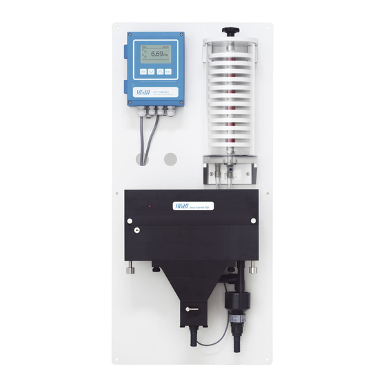
AMI Turbiwell Product Description 2.2. Instrument Overview Panel Quick fastener screw Transmitter Waste 1 Cover with optical Drain valve measurement system deltaT flow sensor (option) Measuring chamber A-96.250.511 / 091120... -
Page 20: Installation
AMI Turbiwell Installation Installation 3.1. Installation Checklist On-site AC variant: 100–240 VAC (10%), 50/60 Hz (5%) requirements DC variant: 10–36 VDC Power consumption: 35 VA maximum. Protective earth connection required. Sample line with sufficient sample flow and pressure (see Instrument Specification, p. -
Page 21: Mounting Of Instrument Panel
AMI Turbiwell Installation 3.2. Mounting of Instrument Panel The first part of this chapter describes the preparing and placing of the system for use. The instrument must only be installed by trained personnel. Mount the instrument in vertical position. - Page 22 Installation CAUTION Inaccurate measured values If the AMI Turbiwell is not exactly aligned in horizontal and verti- cal direction, this can lead to inaccurate measured values. Exactly align the panel in horizontal and vertical direction Use a spirit level to align the panel.
-
Page 23: Installation Of Sample Degasser Option
AMI Turbiwell Installation 3.3. Installation of Sample Degasser Option Overview Star knob Base plate Console Cover Cylinder pin (diam. 6 mm) Sample inlet Bracket Hole 5 mm Fixing screws (4 pcs) Outlet to measuring chamber Plates (12 pcs) Overflow to waste Counter nut A-96.250.511 / 091120... - Page 24 AMI Turbiwell Installation Installation Guide pin Bracket Console Hole 5 mm 1 Screw the brackets [D] to the panel with the enclosed M6 x 16 screws 2 Roughly align the brackets and slightly tighten the screws. 3 Insert the guide pins [C] into the bores of the brackets.
- Page 25 AMI Turbiwell Installation Star knob Cover with guide pin holes Guide pin Sample inlet Outlet to waste Outlet to constant head Degasser labyrinth Acrylic glass tube Threaded hole 5 Put the acrylic glass tube [O] onto the base plate. 6 Insert the degasser labyrinth [N] into the acrylic glass tube.
- Page 26 AMI Turbiwell Installation Q Elbow hose nozzle R Blind screw 14 Replace the elbow hose nozzle [Q] on the constant head with the enclosed blind screw [R]. A-96.250.511 / 091120...
-
Page 27: Installation Of Deltat Option
AMI Turbiwell Installation 3.4. Installation of deltaT Option Overview Sample inlet Manual drain valve deltaT sensor Measuring chamber Sample outlet Panel Locking pin Locking plate Elbow hose nozzle Screw Installation Install the deltaT sensor in vertical position with the sample inlet [A] looking downwards. - Page 28 AMI Turbiwell Installation 6 Turn the elbow hose nozzle [E] upwards clockwise. 7 Install the locking plate [I] 8 Tighten the screw [J]. 9 Screw the deltaT sensor [B] to the panel in vertical position. 10 Connect the tube supplied with the installation kit to the sample outlet [C] of the deltaT sensor and to the sample inlet (elbow hose nozzle [E]) of the constant head.
-
Page 29: Installation Of Flowcontroller Option
AMI Turbiwell Installation 3.5. Installation of Flowcontroller Option Preparations 1 Push the locking pin [D] upward to unlock the measuring chamber. 2 Swivel the measuring chamber [G] out. 3 Remove the sample inlet tube from the elbow hose nozzle [A]. - Page 30 AMI Turbiwell Installation 7 Unscrew the elbow fitting [E] from the inlet of the Flowcontroller. Flowcontroller Elbow fitting 8 Remove the teflon tape from the threads of fittings [A] and [E] and wrap them with new teflon tape. 9 Screw the elbow fitting [E] to the inlet of the constant head and the elbow hose nozzle [A] to the inlet of the flow controller.
- Page 31 AMI Turbiwell Installation Overview Sample inlet of Flowcontroller Elbow fitting Capillary Manual drain valve Flowcontroller Measuring chamber Locking pin Panel Installation 12 Screw the Flowcontroller [C] to the panel. 13 Connect the tube supplied with the installation kit to the sample outlet of the Flowcontroller and to the sample inlet [E] of the con- stant head.
- Page 32 AMI Turbiwell Installation Electrical Connection WARNING Electrical shock hazard Before opening the AMI Transmitter switch power off. 17 Use one of the PG7 cable glands to feed the cable of the sensor into the AMI transmitter housing. 18 Connect the cable to the terminals according to the Connection Diagram, p.
-
Page 33: Connect Sample And Waste
Installation 3.6. Connect Sample and Waste Sample inlet The AMI Turbiwell can be ordered in different configurations. Use plastic tubes with inner diameter 10 mm for: connection to the constant head connection to the deltaT flow meter connection to the Flowcontroller Use plastic tubes with outer diameter 6 mm for connection to the de- gasser. - Page 34 AMI Turbiwell Installation deltaT sensor deltaT sensor sample inlet Drain Waste Flowcontroller Capillary Flowcontroller sample inlet Drain Waste A-96.250.511 / 091120...
- Page 35 AMI Turbiwell Installation Degasser Degasser sample inlet Drain Waste A-96.250.511 / 091120...
-
Page 36: Electrical Connections
AMI Turbiwell Installation 3.7. Electrical Connections WARNING Electrical hazard. Always turn off power before manipulating electric parts. Grounding requirements: Only operate the instrument from a power outlet which has a ground connection. Make sure the power specification of the instrument corre- sponds to the power on site. - Page 37 AMI Turbiwell Installation WARNING External Voltage. Externally supplied devices connected to relay 1 or 2 or to the alarm relay can cause electrical shocks Make sure that the devices connected to the following contacts are disconnected from the power before resuming installation.
-
Page 38: Connection Diagram
AMI Turbiwell Installation 3.7.1 Connection Diagram CAUTION Use only the terminals shown in this diagram, and only for the mentioned purpose. Use of any other terminals will cause short circuits with possible corresponding consequences to material and personnel. A-96.250.511 / 091120... -
Page 39: Power Supply
Mains cable to comply with standards IEC 60227 or IEC requirements 60245; flammable rating FV1 Mains equipped with an external switch or circuit-breaker – near the instrument – easily accessible to the operator – marked as interrupter for AMI Turbiwell A-96.250.511 / 091120... -
Page 40: Relay Contacts
AMI Turbiwell Installation 3.8. Relay Contacts 3.8.1 Input Note: Use only potential-free (dry) contacts. The total resistance (sum of cable resistance and resistance of the relay contact) must be less than 50 Ω. Terminals 16/42 If signal output is set to hold, measurement is interrupted if input is active. -
Page 41: Relay 1 And 2
AMI Turbiwell Installation 3.8.3 Relay 1 and 2 Note: Max. load 1 A/250 VAC Relay 1 and 2 can be configured as normally open or as normally closed. Standard for both relays is normally open. To configure a Re- lay as normally closed, set the jumper in the upper position. - Page 42 AMI Turbiwell Installation CAUTION Risk of damage of the relays in the AMI Transmitter due to heavy inductive load. Heavy inductive or directly controlled loads (solenoid valves, dos- ing pumps) may destroy the relay contacts. To switch inductive loads > 0.1 A use an AMI relay box available as an option or suitable external power relays.
-
Page 43: Signal Outputs
AMI Turbiwell Installation 3.9. Signal Outputs 3.9.1 Signal Output 1 and 2 (current outputs) Note: Max. burden 510 Ω If signals are sent to two different receivers, use signal isolator (loop isolator). Signal output 1: Terminals 14 (+) and 13 (-) -
Page 44: Signal Output 3
AMI Turbiwell Installation 3.10.1 Signal Output 3 The AMI Turbiwell can display a maximum of two measured values: the measured turbidity and the sample flow, if a flow sensor is installed. Therefore, there is no need to install the optional third signal output. -
Page 45: Hart Interface
AMI Turbiwell Installation 3.10.3 HART Interface Terminals 38 (+) and 37 (-). The HART interface PCB allows for communication via the HART protocol. For detailed information, consult the HART manual. HART Interface PCB 3.10.4 USB Interface The USB Interface is used to store Logger data and for Firmware up- load. -
Page 46: Instrument Setup
AMI Turbiwell Instrument Setup Instrument Setup Open Sample Open the sample flow and wait until the measuring chamber is full and the sample flows via overflow into the waste. Flow Switch on power. First, the analyzer performs a self test, displays the firmware version and then starts normal operation. -
Page 47: Calibration, Matching And Verification
The calibration is accepted if the deviation is less than 25 % of the factory calibration. The long-term stability of the AMI Turbiwell can be verified with a ver- ification kit that must be matched against the current calibration. -
Page 48: Ppm Calculation, E.g. "Oil In Water
The calibration line is defined by 2 points: zero point and a scale point (slope). For the determination of the zero point, a sample with- out the opacifier (x = 0) must be supplied to the AMI Turbiwell. The average value over a defined time period is automatically saved as the zero point. - Page 49 AMI Turbiwell Instrument Setup Considerations Considerations for a reliable measurement: The sample must always have the same grade of homogeniza- tion to receive quantitative results. Adequate homogenization can be achieved with a centrifugal or a gear pump. The distance and the time period from sampling to measure- ment should be short enough to ensure that the drop size does not essentially change.
- Page 50 AMI Turbiwell Instrument Setup Process The following must be considered before starting calibration: Drain the measuring chamber and clean it if necessary. calibration For the calibration, oil-free process water and oil is needed. The calibration solutions are prepared in a vessel with a vol- ume of approx.10 liters.
-
Page 51: Operation
AMI Turbiwell Operation Operation 5.1. Function of the Keys Exit Enter to exit a menu or command (rejecting any changes) to move back to the previous menu level to move DOWN in a menu list and to decrease digits to move UP in a menu list and to increase digits... -
Page 52: Measured Values And Symbols On The Display
AMI Turbiwell Operation 5.2. Measured Values and Symbols on the Display 15:20:18 2.53 35.8 l/h A RUN normal operation HOLD input closed or cal delay: Instrument on hold (shows status of signal outputs). input closed: Control/limit is interrupted (shows status of signal outputs). -
Page 53: Software Structure
AMI Turbiwell Operation 5.3. Software Structure Main Menu Messages Diagnostics Maintenance Operation Installation Menu 1: Messages Messages Reveals pending errors as well as an event history Pending Errors (time and state of events that have occurred at an ear- Maintenance List lier point of time) and maintenance requests. -
Page 54: Changing Parameters And Values
AMI Turbiwell Operation 5.4. Changing Parameters and Values Changing The following example shows how to change the logger interval: parameters 1 Select the parameter you want to Sensors Logger 5.1.2 4.4.1 change. Sensor type FOME Log interval 30 min 2 Press [Enter] Disinf. -
Page 55: Maintenance
Maintenance 6.1. Maintenance Schedule The AMI Turbiwell is factory-calibrated using a primary standard (formazine) prior to shipment. The instrument does not require any further calibration before use. A verification is recommended quarter- ly using the Swan Verification Kit, a secondary standard, instead of calibration with a primary standard. -
Page 56: Cleaning The Measuring Chamber
AMI Turbiwell Maintenance 6.2. Cleaning the Measuring Chamber CAUTION Wrong measured values due to dirty optical components. Touching the optical components in the cover of the measuring cell may result in wrong measured values. Cleaning and re-calibration at SWAN is necessary. - Page 57 AMI Turbiwell Maintenance 5 Open the drain valve to flush out the polluted water. If the instru- ment is equipped with the automatic drain valve option: Select <Maintenance>/<Drainage>/<Manual operation>/<Motor valve>/ <open>. 6 Remove calcareous depositions using a common household de- liming agent in standard concentration.
-
Page 58: Cleaning The Degasser
AMI Turbiwell Maintenance 6.3. Cleaning the Degasser Note: Use a soft brush and a mild detergent. Eliminate calcareous depositions with a common household deliming agent in standard concentration. Cleaning To clean the degasser proceed as follows: Star knob Cover with guide pin holes... -
Page 59: Calibration
16 Check for leakage. 6.4. Calibration The AMI Turbiwell is calibrated at the factory using formazine and the curve is permanently stored in the transmitter. In addition, the emission intensity of the LED is monitored by an external photodi- ode. This automatically compensates for an age-related loss of in- tensity. - Page 60 AMI Turbiwell Maintenance Pipette 5 ml Fast-release pipette pump Rubber stopper Volumetric flask Prepare the 1 Put the pipette into the fast-release pipette pump. 20 NTU 2 Make sure that the pump piston is pushed in completely. formazine 3 Turn the pump wheel until the formazine standard 4000 NTU standard reaches the 5 ml level of the pipette.
- Page 61 AMI Turbiwell Maintenance Perform In the maintenance menu, choose calibration and follow the instruc- tions on the screen. calibration 1 Navigate to menu <Maintenance>/ Maintenance 3.32 <Calibration> and press [Enter]. Verification Matching Calibration Simulation Set Time 01.01.05 16:30:00 2 Stop sample flow.
- Page 62 AMI Turbiwell Maintenance You are prompted to choose between: Calibration 3.32.4 [Keep existing] Factor existing 1.00 Factor new 0.92 [Save new]. Keep existing Save new 11 Open the measuring chamber. Calibration 3.32.5 12 Open the drain valve. - Open meas. chamber - Drainage valve open? 13 Remove the rubber stopper.
- Page 63 AMI Turbiwell Maintenance Seal the overflow Cover Drain valve Measuring chamber Overflow (drain 1) Overflow chamber Rubber stopper Cover Measuring chamber Overflow chamber Drain valve Overflow (Drain 1) Rubber stopper Constant head A-96.250.511 / 091120...
-
Page 64: Verification
The <Matching> function can be started in menu <Maintenance>/<Matching>. Up to 10 Verikits can be matched for one AMI Turbiwell. An existing Verikit can be overwritten but not deleted. Note: It is very important that the drainage valve is closed during the matching process. - Page 65 AMI Turbiwell Maintenance The signal outputs are frozen during matching. When the matching is finished, the signal outputs remain frozen for the time programmed in <hold after cal.>. During this time the display shows HOLD. For possible error messages, see Troubleshooting, p.
- Page 66 AMI Turbiwell Maintenance 8 Select “Assign Value” with the Matching 3.2.1 ] key and press [Enter]. VERIKIT # 9 Set the required value using the Assign Value 5.00 FNU ] and [ ] keys. –Solid verikit: Enter the value print- <Enter>...
- Page 67 AMI Turbiwell Maintenance Verification 1 Navigate to menu <Maintenance>/ Verification 3.1.2 <Verification> and press [Enter]. SWAN Verikit 2 Select SWAN Verikit and press Other method [Enter]. 3 Choose a Verikit from the list. Verification 3.1.1 4 Press [Enter]. VERIKIT #...
- Page 68 AMI Turbiwell Maintenance Installation of Insert and fix the verification kit as shown below. If a liquid verifica- tion kit is used, also perform the steps described in Preparation be- the Verikit fore use, p. Cover Barrier Verification kit Fixing plate with cylindrical pin...
- Page 69 AMI Turbiwell Maintenance Verification The Verification Kit Turbiwell Liquid can be filled with any aqueous suspension or emulsion, provided that the suspension or emulsion is Kit Turbiwell compatible with the materials used. Liquid Housing: Windows: PMMA Screw plugs: PVDF Note: The Verification Kit Turbiwell Liquid is suitable for...
- Page 70 AMI Turbiwell Maintenance Preparation Before inserting the verification kit into the measuring chamber, per- form the following steps: before use 1 Shake to obtain a homogeneous mixture. 2 Place the cuvette as shown below. Tap against the cuvette to let all air rise to the top.
- Page 71 AMI Turbiwell Maintenance Cleaning the CAUTION Verification Kit Damage to optical surfaces Never use organic agents i. e. alcohol to clean the optical surfac- es of the verification kit. Use a dry cleaning cloth for lenses to clean the optical surfaces [A].
-
Page 72: Wet Verification
AMI Turbiwell Maintenance 6.5.2 Wet Verification Wet verification can be used instead of verification with a Verikit. It is performed with a standard with a known turbidity filled into the mea- suring chamber instead of the sample. Note: When performing a wet verification do not use a standard below 1 FNU/NTU. - Page 73 AMI Turbiwell Maintenance 12 Enter the turbidity of the standard as Other method 3.1.2.5 the reference value. Reference value 14.0 FNU 13 Press [Enter]. <Enter> to continue The verification is running. Other method 3.1.2.5 Actual value 21.7 FNU Reference value 21.6 FNU...
-
Page 74: Longer Stop Of Operation
AMI Turbiwell Maintenance 6.6. Longer Stop of Operation Do not switch off the instrument if your operation is suspended for less than a week. Power consumption is very low and the turbidime- ter remains ready for use. If water hardness is very high, lime deposition may precipitate. -
Page 75: Troubleshooting
AMI Turbiwell Troubleshooting Troubleshooting 7.1. Calibration Errors Error message: Deviation too big!! Please check manual. Possible cause Corrective Action Wrong formazine stan- Check formazine standard. If dard. necessary prepare a new formazine standard, see Prepare the 20 NTU formazine standard, p. -
Page 76: Error List
AMI Turbiwell Troubleshooting 7.4. Error List Error Non-fatal Error. Indicates an alarm if a programmed value is exceeded. Such Errors are marked E0xx (bold and black). Fatal Error (blinking symbol) Control of dosing devices is interrupted. The indicated measured values are possibly incorrect. - Page 77 AMI Turbiwell Troubleshooting Error Description Corrective action – check process E001 Alarm high – check programmed value 5.3.1.1.1, p. – check process E002 Alarm low – check programmed value 5.3.1.1.25, p. – turbidity out of range E005 Range – disappears if measuring chamber is filled –...
- Page 78 AMI Turbiwell Troubleshooting Error Description Corrective action – call service E031 Calibration Recout – call service E032 Wrong Frontend – none, normal status E033 Power-on – none, normal status E034 Power-down A-96.250.511 / 091120...
-
Page 79: Replacing Fuses
AMI Turbiwell Troubleshooting 7.5. Replacing Fuses WARNING External Voltage. Externally supplied devices connected to relay 1 or 2 or to the alarm relay can cause electrical shocks Make sure that the devices connected to the following contacts are disconnected from the power before resuming installation. -
Page 80: Program Overview
AMI Turbiwell Program Overview Program Overview For explanations about each parameter of the menus see Program List and Explanations, S. Menu 1 Messages: informs about pending errors and mainte- nance tasks and shows the error history. Password protection possible. No settings can be modified. -
Page 81: Diagnostics (Main Menu 2)
AMI Turbiwell Program Overview 8.2. Diagnostics (Main Menu 2) Identification Designation AMI Turbiwell * Menu numbers 2.1* Version V6.23-09/19 Version TURBI 1.35 Factory Test 2.1.4* Operating Time 2.1.5* Sensors Turbidity Turbidity FNU /NTU 2.2* 2.2.1* (Raw value) Quotient Scale Factor 1... -
Page 82: Maintenance (Main Menu 3)
AMI Turbiwell Program Overview I/O State 2.4.1* * Menu numbers Alarm Relay 2.4* 2.4.2* Relay 1/2 Input Signal Output 1/2 Interface 2.5.1* (only with RS485 Protocol 2.5* interface) Baud rate 8.3. Maintenance (Main Menu 3) Verification SWAN VERIKIT # 3.1.1* 3.1*... -
Page 83: Operation (Main Menu 4)
AMI Turbiwell Program Overview If the unit ppm is selected Process Cal. ppm 3.1.1* * Menu numbers Detect Zero 3.1* 3.1.2* Specify Slope Simulation 3.2* Set Time 3.3* Drainage 3.4* 8.4. Operation (Main Menu 4) Sensors 4.1.1* Filter Time Const. -
Page 84: Installation (Main Menu 5)
AMI Turbiwell Program Overview 8.5. Installation (Main Menu 5) Sensors * Menu numbers Sensor type 5.1.1* 5.1* Dimension 5.1.2* Flow 5.1.3.1* Flow measurement 5.1.3* Slope 5.1.3.2* 5.1.4 Offset Signal Outputs Signal Output 1 & 2 Parameter 5.2.1.1 & 5.2.2.1* 5.2* 5.2.1* &... - Page 85 AMI Turbiwell Program Overview Miscellaneous 5.4.1* * Menu numbers Language 5.4* 5.4.2* Set defaults Load Firmware 5.4.3* Password 5.4.4.1* Messages 5.4.4* 5.4.4.2* Maintenance 5.4.4.3* Operation 5.4.4.4* Installation Sample ID 5.4.5* 5.4.6 Line break detection Interface 5.5.1* (only with RS485 Protocol 5.5*...
-
Page 86: Program List And Explanations
AMI Turbiwell Program List and Explanations Program List and Explanations 1 Messages 1.1 Pending Errors Provides the list of active errors with their status (active, acknowl- edged). If an active error is acknowledged, the alarm relay is active again. Cleared errors are moved to the Message list. - Page 87 AMI Turbiwell Program List and Explanations 2.2.3.1.1 Number: Calibration counter. Date, Time: Date and time of the calibration. Factor cal.: Factor of the last calibration. Factor active: Current factor in use for the measurement. 2.2.3.2 Ver. history: Only for diagnostic purposes. Review the values of the last verifications.
-
Page 88: Maintenance
AMI Turbiwell Program List and Explanations 2.4 I/O State 2.4.1- 2.4.2 Shows the actual status of all in- and outputs. Active or inactive Alarm Relay: Active or inactive Relay 1 and 2: Open or closed Input: Signal Output 1 and 2: Actual current in mA... - Page 89 AMI Turbiwell Program List and Explanations 3.4 Simulation To simulate a value or a relay state, select the alarm relay, relay 1 and 2 signal output 1 and 2 with the [ ] or [ ] key.
- Page 90 AMI Turbiwell Program List and Explanations 3.6.2.1 Interval 3.6.1.20 Interval: The draining interval can be programmed within a range of 1–23 h. 3.6.2.3 Duration: Enter the duration of the draining valve being opened. Range: 5–300 sec. 3.6.2.4 Delay: During duration plus the delay time the signal and control out- puts are held in the operating mode.
- Page 91 AMI Turbiwell Program List and Explanations 3.6.2.22 Calendar: 3.6.2.22.1 Start time: The programmed start time is valid for each of the pro- grammed days. 3.6.2.22.2 Monday: Possible settings, on or off 3.6.2.22.8 Sunday: Possible settings, on or off 3.6.2.3 Duration: see Interval 3.6.2.4...
-
Page 92: Operation
AMI Turbiwell Program List and Explanations 4 Operation 4.1 Sensors 4.1.1 Filter time constant: Used to damp noisy signals. The higher the filter time constant, the slower the system reacts to changes of the mea- sured value. Range: 5–300 sec 4.1.2... -
Page 93: Installation
AMI Turbiwell Program List and Explanations 5 Installation 5.1 Sensors 5.1.1 Sensor type: Display of the used sensor type (e.g. Well IR) 5.1.2 Dimension: Choose the measurement unit (FNU, NTU or ppm) 5.1.3 Flow: Select a flow measurement method. 5.1.3.1 Flow measurement: Select the type of flow sensor if a flow sensor is installed. - Page 94 AMI Turbiwell Program List and Explanations As process The process value can be represented in 3 ways: linear, bilinear or logarithmic. See graphs below. values [mA] 0 / 4 linear X Measured value bilinear [mA] 0 / 4 1’000 10’000 X Measured value (logarithmic) 5.2.1.40...
- Page 95 AMI Turbiwell Program List and Explanations As control Signal outputs can be used for driving control units. We distinguish different kinds of controls: output P-controller: The controller action is proportional to the devia- tion from the setpoint. The controller is characterized by the P- Band.
- Page 96 AMI Turbiwell Program List and Explanations Control upwards or downwards 5.2.1.43 Control Parameters: Meas. value 5.2.1.43.10 Setpoint: User-defined process value (Measured value or flow) Range: 0–250 FNU/NTU 5.2.1.43.20 P-Band: Range below (upwards control) or above (downwards control) the set-point, within the dosing intensity is reduced from 100% to 0% to reach the set-point without overshooting.
- Page 97 AMI Turbiwell Program List and Explanations 5.3.1.1 Alarm 5.3.1.1.1 Alarm High: If the measured value rises above the alarm high value, the alarm relay is activated and E001, is displayed in the message list. Range: 0–250 FNU /NTU 5.3.1.1.25 Alarm Low: If the measured value falls below the alarm low value, the alarm relay is activated and E002 is displayed in the message list.
- Page 98 AMI Turbiwell Program List and Explanations Note: The navigation in the menu <Relay 1> and <Relay 2> is equal. For reason of simplicity only the menu numbers of Relay 1 are used in the following. 1 First select the functions as:...
- Page 99 AMI Turbiwell Program List and Explanations 5.3.2.32.20 Cycle time: duration of one control cycle (on/off change). Range: 0–600 sec. 5.3.2.32.30 Response time: Minimal time the metering device needs to react. Range: 0–240 sec. 5.3.2.32.4 Control Parameters: Range for each Parameter same as 5.2.1.43, p.
- Page 100 AMI Turbiwell Program List and Explanations 5.3.2.6 Signal Outputs: Select operating mode of the signal output: Signal outputs continue to issue the measured value. Cont.: Hold: Signal outputs hold the last valid measured value. Measurement is interrupted. Errors, except fatal errors, are not issued.
- Page 101 AMI Turbiwell Program List and Explanations 5.3.2.342.2 Monday: Possible settings, on or off 5.3.2.342.8 Sunday: Possible settings, on or off 5.3.2.44 Run Time: see Interval 5.3.2.54 Delay: see Interval 5.3.2.6 Signal Outputs: see Interval 5.3.2.7 Output/Control: see Interval 5.3.2.1 Function = Fieldbus The relay will be switched via the Profibus input.
- Page 102 AMI Turbiwell Program List and Explanations 5.3.4.5 Delay: Time which the instrument waits, after the input is deactivated, before returning to normal operation. Range: 0–6‘000 Sec 5.4 Miscellaneous 5.4.1 Language: Set the desired language. Available settings: German/English/French /Spanish 5.4.2 Set defaults: Reset the instrument to factory default values in three different ways: ...
- Page 103 AMI Turbiwell Program List and Explanations 5.5 Interface Select one of the following communication protocols. Depending on your selection, different parameters must be defined. 5.5.1 Protocol: Profibus 5.5.20 Device address: Range: 0–126 5.5.30 ID-Nr.: Range: Analyzer; Manufacturer; Multivariable 5.5.40 Local operation: Range: Enabled, Disabled 5.5.1...
-
Page 104: Default Values
AMI Turbiwell Default Values Default Values Operation Sensors Filter Time Const.: ................30 s Hold after Cal.:................300 s Alarm Relay .................same as in Installation Relay 1 & 2 .................same as in Installation Input .................same as in Installation Logger Logger Interval:................ 30 min Clear Logger:.................. - Page 105 AMI Turbiwell Default Values Settings: Control Parameters: Derivative Time: ......0 s Settings: Control Parameters: Control Timeout:..... 0 min Settings: Actuator:........... Time proportional Cycle time: ................60 s Response time: ............... 10 s Settings: Actuator............. Motor valve Run time: ................. 60 s Neutral zone: ................
-
Page 106: Index
AMI Turbiwell Index Index ... Instrument Setup ...... - Page 107 AMI Turbiwell Index ....Sample inlet .....
-
Page 108: Notes
AMI Turbiwell Notes Notes A-96.250.511 / 091120... - Page 109 AMI Turbiwell Notes A-96.250.511 / 091120...
- Page 110 Swan Products - Analytical Instruments for: Swan is represented worldwide by subsidiary companies and distributors and cooperates with independent representatives all over the world. For contact in- formation, please scan the QR code. Swan Analytical Instruments ∙ CH-8340 Hinwil www.swan.ch ∙ swan@swan.ch AMI Turbiwell...
Need help?
Do you have a question about the AMI Turbiwell and is the answer not in the manual?
Questions and answers
How often should i match? We currently perform monthly validations and sometimes the validation fails so i like to match. A chap here said you should only match yearly which doesnt make sense to me. Please could you clarify. I work at a water treatment works