Table of Contents
Advertisement
Quick Links
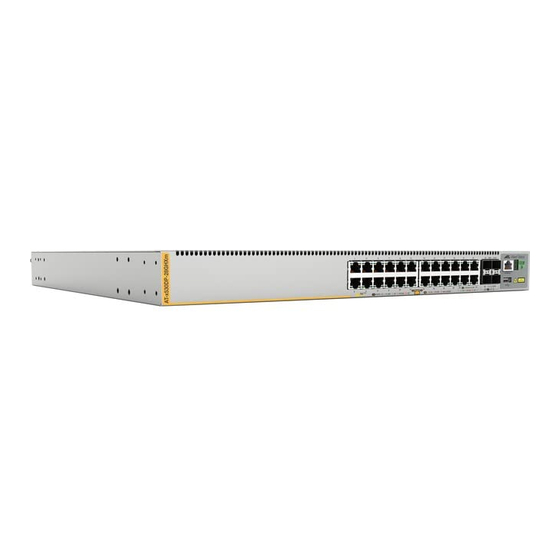
x530DP Series
Stackable Gigabit Layer 3+ Ethernet Switches
AlliedWare Plus™ v5.5.1-2.1
x530DP-28GHXm
x530DP-52GHXm
1
3
5
7
9
11
2
4
6
8
10
12
Installation Guide for Virtual Chassis
Stacking
613-002695 Rev. B
1
2
13
15
17
19
21
23
25
14
16
18
20
22
24
26
PORTS 1-40
1G LINK
ACT
100 LINK
ACT
PORTS 1-24
3
5
7
9
11
13
15
4
6
8
10
12
14
16
PORTS 1-20
1G LINK
ACT
100 LINK
ACT
PD ON
PD ERR
27
29
31
33
35
37
39
28
30
32
34
36
38
40
PD ON
PD ERR
MAX CURRENT
PORTS 25-48
17
19
21
23
25
SFP+
27/S1
CONSOLE
18
20
22
24
26
10G/1G
28/S2
5G/2.5G/1G LINK
MAX CURRENT
ACT
100 LINK
ACT
41
43
45
47
49
SFP+
51/S1
CONSOLE
42
44
46
48
50
10G/1G
52/S2
5G/2.5G/1G LINK
ACT
100 LINK
ACT
CLASS 1
LASER PRODUCT
4624
CLASS 1
LASER PRODUCT
4625
Advertisement
Table of Contents

Related Manuals for Allied Telesis x530DP Series


Summary of Contents for Allied Telesis x530DP Series
- Page 1 Series Stackable Gigabit Layer 3+ Ethernet Switches AlliedWare Plus™ v5.5.1-2.1 x530DP-28GHXm x530DP-52GHXm SFP+ 27/S1 CONSOLE CLASS 1 LASER PRODUCT 10G/1G 28/S2 5G/2.5G/1G LINK PORTS 1-20 1G LINK 100 LINK PD ON PD ERR MAX CURRENT 100 LINK 4624 SFP+...
- Page 2 Allied Telesis, Inc. has been advised of, known, or should have known, the...
- Page 3 Electrical Safety and Emissions Standards This product meets the following standards. U.S. Federal Communications Commission Radiated Energy Note: This equipment has been tested and found to comply with the limits for a Class A digital device pursuant to Part 5 of FCC Rules.
- Page 4 Translated Safety Statements Important: Safety statements that have the symbol are translated into multiple languages in the Translated Safety Statements document at www.alliedtelesis.com/en/documents/translated- safety-statements. Remarque: Les consignes de sécurité portant le symbole sont traduites dans plusieurs langues dans le document Translated Safety Statements, disponible à l'adresse www.alliedtelesis.com/en/ documents/translated-safety-statements.
-
Page 5: Table Of Contents
Contents Preface: .....................................13 Document Conventions ...............................14 Contacting Allied Telesis ..............................15 Chapter 1: Overview ................................ 17 Front and Rear Panels ................................18 Management Panel ................................19 Features ....................................20 x530DP Models ................................20 .....................................20 Twisted Pair Ports ................................20 Power Over Ethernet ..............................21 SFP+ Transceiver Ports ...............................21 LEDs.....................................22... - Page 6 Contents Stack Trunks of 5Gbps Twisted Pair Ports ......................... 58 Invalid Stack Trunks................................62 Example 1..................................62 Example 2..................................62 Example 3..................................63 Example 4..................................63 Master and Member Switches ............................64 Selection of the Master Switch ............................ 64 Switch ID Numbers ................................66 Optional Feature Licenses ..............................
- Page 7 Series Installation Guide for Virtual Chassis Stacking General Steps for the Master Switch..........................133 Configuring the Master Switch - Part I........................134 Configuring the Master Switch - Part II........................137 Verifying the Master Switch ............................139 What to Do Next .................................140 Configuring Member Switches............................142 General Steps for the Member Switch........................142...
- Page 8 Contents...
- Page 9 Figures Figure 1: Front Panel of the x530DP-28GHXm Switch......................18 Figure 2: Front Panel of the x530DP-52GHXm Switch......................18 Figure 3: Back Panel of the x530DP Series Switch......................18 Figure 4: Management Panel ...............................19 Figure 5: Non-PoE Power Supplies ............................25 Figure 6: System and PoE Power Supplies..........................26 Figure 7: FAN10 and FAN10R Fan Modules........................28...
- Page 10 Figures Figure 50: SHOW STACK Command ..........................151 Figure 51: Installing an SFP Transceiver..........................156 Figure 52: Positioning the SFP or SFP+ Handle in the Up Position ...................157 Figure 53: Connecting a Fiber Optic Cable to an SFP or SFP+ Transceiver ..............157 Figure 54: Installing SP10TW Cables ..........................159 Figure 55: x530DP-28GHXm and x530DP-52GHXm Switch Dimensions................167 Figure 56: FAN10 Dimensions............................167...
- Page 11 Tables Table 1: Basic Features ...............................20 Table 2: System and PoE Power Supply Summary ......................26 Table 3: x530DP-28GHXm Switch Twisted Pair Port Specifications ...................29 Table 4: x530DP-52GHXm Switch Twisted Pair Port Specifications ...................30 Table 5: x530DP-28GHXm Twisted Pair Ports 1 - 24 LED Functions .................33 Table 6: x530DP-52GHXm Twisted Pair Ports 1 - 48 LED Functions .................34 Table 7: IEEE Powered Device Classes ..........................37 Table 8: Power Supply Budgets of the Power Supplies ......................37...
- Page 12 Tables...
-
Page 13: Preface
Preface This guide contains the installation instructions for the x530DP Series of stackable Gigabit, Layer 3+ Ethernet switches. This preface contains the following sections: “Document Conventions” on page 14 “Contacting Allied Telesis” on page 15 Note This guide explains how to install switches as a stack with Virtual ™... -
Page 14: Document Conventions
Preface Document Conventions This document uses the following conventions: Note Notes provide additional information. Caution Cautions inform you that performing or omitting a specific action may result in equipment damage or loss of data. Warning Warnings inform you that performing or omitting a specific action may result in bodily injury. -
Page 15: Contacting Allied Telesis
guides, software release notes, white papers and data sheets for your product. Warranty - View a list of products to see if Allied Telesis warranty applies to the product you purchased and register your warranty. Allied Telesis Helpdesk - Contact a support representative. - Page 16 Preface...
-
Page 17: Chapter 1: Overview
Note This guide explains how to install switches as a stack with Virtual ™ Chassis Stacking (VCStack ). For instructions on how to install the devices as standalone switches, refer to the x530DP Series Installation Guide for Standalone Switches. -
Page 18: Front And Rear Panels
Chapter 1: Overview Front and Rear Panels The front panel of the x530DP Series switch is shown in Figure 1 and Figure 2. SFP+ 27/S1 CONSOLE CLASS 1 LASER PRODUCT 10G/1G 28/S2 5G/2.5G/1G LINK PORTS 1-20 1G LINK 100 LINK... -
Page 19: Management Panel
Series Installation Guide for Virtual Chassis Stacking Management Panel Figure 4 identifies the components on the management panel. Switch ID LED Console Management eco-friendly Port Button CONSOLE Port CLASS 1 LASER PRODUCT 4567 Figure 4. Management Panel... -
Page 20: Features
Chapter 1: Overview Features The Allied Telesis x530DP Series switches are stackable Gigabit, Layer 3+ Ethernet switches. The following sections list the features: x530DP Models Table 1 lists the basic features for the switch model. Table 1. Basic Features 10/100/1000T 10/100/1000T 100/1G/2.5G/5G... -
Page 21: Power Over Ethernet
Series Installation Guide for Virtual Chassis Stacking MDI/MDI-X at 100Mbps PoE+ supported on ports 1 to 24 PoE++ supported on ports 25 to 48 Port Link/Activity (L/A) and PoE LEDs The 24 twisted pair ports on the x530DP-28GHXm switch have these... -
Page 22: Leds
Industrial (-40 to 85° C) and extended (-40 to 105° C) temperature transceivers are available. Note For a current list of supported transceiver modules refer to the x530DP Series Data Sheet. The following restrictions on SFP+ transceivers apply: 100Mbps transceivers are not supported ... -
Page 23: Management Software And Interfaces
Series Installation Guide for Virtual Chassis Stacking Management The management software and interfaces are: Software and AlliedWare Plus Management Software Interfaces Command line interface (CLI) Management The following methods are used for managing the switches: Methods Local management through the Console port ... -
Page 24: Power Supplies
Chapter 1: Overview Power Supplies This section describes the two types of power supplies for the x530DP switches: “Non-PoE Power Supplies,” next “System and PoE Power Supplies” on page 25: Non-PoE Power Here are the non-PoE power supplies: Supplies PWR150 ... -
Page 25: System And Poe Power Supplies
Series Installation Guide for Virtual Chassis Stacking The PWR150, PWR150R, and PWR250 power supplies have AC power connectors. The PWR250-80 power supply has a DC connector for DC wiring environments. Figure 5. Non-PoE Power Supplies System and PoE... -
Page 26: General Guidelines
Chapter 1: Overview Figure 6. System and PoE Power Supplies The PoE power budgets and the maximum number of supported ports are summarized in Table 2. Table 2. System and PoE Power Supply Summary Number of Maximum Supported PoE Ports System and PoE Power Power Supply... - Page 27 Series Installation Guide for Virtual Chassis Stacking Warning Power cord is used as a disconnection device. To de-energize equipment, disconnect the power cord. E3 Warning This unit might have more than one power cord. To reduce the risk of electric shock, disconnect all power cords before servicing the unit.
-
Page 28: Fan10 And Fan10R Cooling Fans
Chapter 1: Overview FAN10 and FAN10R Cooling Fans The cooling units for the chassis are the FAN10 and FAN10R fan modules. Refer to Figure 7. Figure 7. FAN10 and FAN10R Fan Modules Here are the fan module guidelines: The fan modules have different airflow directions. The FAN10 ... -
Page 29: Twisted Pair Ports
Series Installation Guide for Virtual Chassis Stacking Twisted Pair Ports The specifications of the twisted pair ports are listed in Table 3 and Table 4 on page 30. Table 3. x530DP-28GHXm Switch Twisted Pair Port Specifications Specification Description Port Speed Ports 1 - 20: 10/100Mbps or 1Gbps. -
Page 30: Speed
Chapter 1: Overview Table 4. x530DP-52GHXm Switch Twisted Pair Port Specifications Specification Description Port Speed Ports 1 - 40: 10/100Mbps or 1Gbps. Ports 41 - 48: 1/2.5/5Gbps Ports 1 - 40: Set the port speed manually or with Auto-Negotiation at 10/100Mbps. Ports 41 - 48: The port speed is set with Auto-Negotiation only, at 1Gbps and higher. -
Page 31: Duplex Mode
Series Installation Guide for Virtual Chassis Stacking Note The ports must be set to Auto-Negotiation to function at 1/2.5/5Gbps speeds and are not compatible with devices that are not IEEE 802.3u-compliant. Duplex Mode The twisted pair ports can operate in either half- or full-duplex mode at 10/100Mbps and full-duplex mode only at higher speeds. -
Page 32: Cable Requirements
Chapter 1: Overview Cable The minimum category of twisted pair cable requirements are as follows: Requirements 10/100Mbps ports: Standard TIA/EIA 568-B-compliant Category 3 unshielded cabling. 1000Mbps ports: Standard TIA/EIA 568-A-compliant Category 5 or TIA/EIA 568-B-compliant Enhanced Category 5 (Cat 5e) unshielded cabling. -
Page 33: Table 5: X530Dp-28Ghxm Twisted Pair Ports 1 - 24 Led Functions
Series Installation Guide for Virtual Chassis Stacking Table 5. x530DP-28GHXm Twisted Pair Ports 1 - 24 LED Functions Ports State Description Solid Green The port has established a 1Gbps link to a network device. 1 - 20 Flashing Green The port is transmitting or receiving data at 1Gbps. -
Page 34: Figure 9: X530Dp-52Ghxm Twisted Pair Ports 1-48 Leds
Chapter 1: Overview x530DP-52GHXm The x530DP-52GHXm LEDs indicate Link/Activity (L/A) and PoE (PD ON/PD ERR/MAX CURRENT) information. These LEDs are shown in Figure 9. L/A LED PoE LED Figure 9. x530DP-52GHXm Twisted Pair Ports 1-48 LEDs The states of the x530DP-52GHXm LEDs are described in Table 6. Table 6. - Page 35 Series Installation Guide for Virtual Chassis Stacking Table 6. x530DP-52GHXm Twisted Pair Ports 1 - 48 LED Functions (Continued) Ports State Description Solid Green PD On - The switch is delivering power to a powered device connected to the port.
-
Page 36: Power Over Ethernet
(PD). Examples include wireless access points, IP telephones, webcams, and even other Ethernet switches. The x530DP Series switch automatically determines whether devices connected to its ports are powered devices. Ports that are connected to network nodes that are not powered devices (that is, devices that receive their power from another power source) function as regular Ethernet ports, without PoE. -
Page 37: Powered Device Classes
Series Installation Guide for Virtual Chassis Stacking Powered Device Powered devices are grouped into the seven classes listed in Table 7. The classes are based on the amount of power the devices require. The switch Classes supports all seven classes. -
Page 38: Table 9: Power Budgets Of The Pwr800 Power Supply
Chapter 1: Overview Another factor that determines the power budget of the switch is the number of PoE power supplies in the device. The power budget of a PoE switch that has only one PoE power supply is equal to the budget of the power supply. -
Page 39: Port Prioritization
Series Installation Guide for Virtual Chassis Stacking The switch can handle different power requirements on different ports. This enables you to connect different classes of PoE equipment to the ports on the switch. Port If the power requirements of the powered devices exceed the switch... -
Page 40: Wiring Implementation
10Base-T and 100Base-TX devices that carry the network data. With Mode B, power is provided over the spare wires. The ports on the x530DP Series switch deliver power using Mode A. Powered devices that comply with the IEEE 802.3af standard are required to support both Modes A and B. -
Page 41: Sfp+ Transceiver Ports
Series Installation Guide for Virtual Chassis Stacking SFP+ Transceiver Ports The x530DP-28GHXm switch has four ports (ports 25 - 28) and the x530DP-52GHXm switch has four ports (ports 49 - 52) for 1Gbps SFP and 10Gbps SFP+ transceivers. SFP and SFP+ See “SFP+ Transceiver Ports”... -
Page 42: Table 11: Link And Activity Status Leds For The 1Gbps And 10Gbps Ports
Chapter 1: Overview The LEDs display link status and activity. The possible LED states are described in Table 11. Table 11. Link and Activity Status LEDs for the 1Gbps and 10Gbps Ports State Description Solid Green The transceiver has established a 10Gbps link to a network device. -
Page 43: Eco-Friendly Button
Series Installation Guide for Virtual Chassis Stacking eco-friendly Button The eco-friendly button on the front panel of the switch is used to toggle the port LEDs on or off. You can turn off the LEDs to conserve electricity when you are not monitoring the device. You can also toggle the LEDs... -
Page 44: Vcstack Feature
Note This guide explains how to install switches as a stack with Virtual Chassis Stacking (VCStack). For instructions on how to install the devices as standalone switches, refer to the x530DP Series Installation Guide for Standalone Switches. -
Page 45: Switch Id Led
Series Installation Guide for Virtual Chassis Stacking Switch ID LED The switch ID LED, shown in Figure 11, displays the ID number of the switch. A standalone switch has the ID number 0. Switches in a VCStack have the numbers 1 to 8. Chapter 9, “Building the Stack Trunk with 5Gbps Multi-Speed Ports”... -
Page 46: Figure 12: Switch Id Led Description
Chapter 1: Overview The states of the LED when the switch is not operating in the low power mode are shown in Figure 12. The switch is booting up. The switch has encountered a fault condition. The switch is operating as a standalone unit. The switch has an ID number of 1 to 8 as part of a VCStack. -
Page 47: Usb Port
Series Installation Guide for Virtual Chassis Stacking USB Port The USB port on the management panel is used for the following functions: Store configuration files on flash drives. Restore configuration files to switches that have lost or corrupted ... -
Page 48: Console Port
Chapter 1: Overview Console Port The Console port is an RS232 serial management port. You use the port to access the AlliedWare Plus management software on the switch to configure the feature settings or monitor status or statistics. This type of management is commonly referred to as local management because you have to be at the physical location of the switch and use the management cable included with the unit. -
Page 49: Chapter 2: Virtual Chassis Stacking
Chapter 2 Virtual Chassis Stacking The sections in this chapter are listed here: “Overview” on page 50 “Stacking Guidelines” on page 51 “Stack Trunks” on page 53 “Stack Trunks of SFP+ 10Gbps Ports” on page 54 “Stack Trunks of 5Gbps Twisted Pair Ports”... -
Page 50: Overview
Chapter 2: Virtual Chassis Stacking Overview The VCStack feature is used to connect multiple x530DP Series switches into a single, virtual networking unit. Some of the benefits of the VCStack feature are listed here: Simplifies management - You can manage the devices of the stack ... -
Page 51: Stacking Guidelines
SFP+ transceivers and direct attach cables used for a stack trunk must be from Allied Telesis. Switches will not form a stack with transceivers from other network equipment providers. For a list of supported transceivers, refer to the product data sheet on the Allied Telesis web site. - Page 52 Chapter 2: Virtual Chassis Stacking On a 52-port switch with multi-speed ports, it is possible to create one stack link (maximum bandwidth 20Gbps) group with 4 ports (41 to 44) and one stack link (maximum bandwidth 20Gbps) group with 4 ports (45 to 48). The maximum bandwidth of the entire chassis unit is 20Gbps.
-
Page 53: Stack Trunks
Series Installation Guide for Virtual Chassis Stacking Stack Trunks Stack trunks connect the switches of a stack together. A stack trunk consists of a minimum of two ports on each device. For switches with AlliedWare Plus v5.5.0-1 or later, you can choose two ports of the trunk. -
Page 54: Stack Trunks Of Sfp+ 10Gbps Ports
SFP+ transceivers must be from Allied Telesis and be approved for use in the product. For a list of supported 10Gbps SFP+ transceivers, refer to the product data sheet on the Allied Telesis web site. Note Transceivers are purchased separately. -
Page 55: Figure 13: Stack Trunks Using The Default Stacking Sfp+ Ports
Series Installation Guide for Virtual Chassis Stacking Figure 13 shows examples of stack trunks of the default SFP+ stacking ports for two, three, and four x530DP Series switches. Stack of Two Switches Stack of Three Switches Stack of Four Switches... -
Page 56: Figure 14: Stack Trunks Using Sfp+ Ports
Chapter 2: Virtual Chassis Stacking In stacks of three or four x530DP Series switches the amount of inter- switch network traffic might require a stacking trunk with greater bandwidth than that provided by the default ports. For such situations the additional ports can also be used as trunk ports. -
Page 57: Figure 15: 10Gbps Stack Trunk With Both Sfp+ Fiber Optic Transceivers And Sp10Tw Direct Connect Cables
Series Installation Guide for Virtual Chassis Stacking 10Gbps stack trunks can have both fiber optic transceivers and SP10TW direct attach cables. The example in Figure 15 illustrates a stack of four switches located in two separate buildings. SP10TW direct attach cables connect switches that are in the same wiring closet while fiber optic transceivers connect the switches across the buildings. -
Page 58: Stack Trunks Of 5Gbps Twisted Pair Ports
Chapter 2: Virtual Chassis Stacking Stack Trunks of 5Gbps Twisted Pair Ports The 10Gbps SFP+ ports are not the only ports you can use for a trunk of a stack. If you prefer to use the 10Gbps ports for other functions you can use the 5Gbps twisted pair ports for the trunk instead. -
Page 59: Figure 16: Trunks Of 5Gbps Ports For Stacks Of Two Switches
Series Installation Guide for Virtual Chassis Stacking A trunk of 5Gbps ports for a stack of two switches can have two or more links per switch. As mentioned previously, the more links in a trunk, the greater its bandwidth and resiliency. Examples are shown in Figure 16. -
Page 60: Figure 17: Trunks Of 5Gbps Ports For Stacks Of Three Switches
Chapter 2: Virtual Chassis Stacking A trunk of 5Gbps ports for a stack of three switches can have two or more ports per switch. Refer to Figure 17. Figure 17. Trunks of 5Gbps Ports for Stacks of Three Switches... -
Page 61: Figure 18: Trunks Of 5Gbps Ports For Stacks Of Four Switches
Series Installation Guide for Virtual Chassis Stacking A trunk of 5Gbps ports for a stack of four switches can also have two or more ports per switch. Refer to Figure 18. Figure 18. Trunks of 5Gbps Ports for Stacks of Four Switches... -
Page 62: Invalid Stack Trunks
Chapter 2: Virtual Chassis Stacking Invalid Stack Trunks Figure 19 through Figure 22 on page 63 show examples of invalid stack trunks. Example 1 Stack trunks must be direct links between trunk ports. There cannot be any intermediary networking devices, such as media converters, Ethernet switches, or routers, between trunk ports. -
Page 63: Example 3
Series Installation Guide for Virtual Chassis Stacking Example 3 Trunks must have the same number of physical links between switches. Figure 21 is invalid because the top and middle switches are connected with two links while the top and middle switches are connected to the bottom switch with only one link each. -
Page 64: Master And Member Switches
assigns new ID numbers to resolve situations where two or more switches have the same ID number. Verify that the stacking transceivers are from Allied Telesis and they are cabled correctly. The parameter settings of the switches of the stack are stored in configuration files in the flash memories of the master and member switches. - Page 65 Series Installation Guide for Virtual Chassis Stacking When switches have the same priority values, they compare their MAC addresses to select the master switch. As with the priority value, the lower the MAC address, the higher the priority. The switch with the lowest MAC address becomes the master switch.
-
Page 66: Switch Id Numbers
Chapter 2: Virtual Chassis Stacking Switch ID Numbers Each switch in a stack must have a unique ID number. The possible ID numbers depend on the version number of the AlliedWare Plus management software. The ID numbers 1 to 8 for the eight switches in a stack with AlliedWare Plus v5.5.1 or later. -
Page 67: Optional Feature Licenses
Unlocking optional features requires licenses from Allied Telesis. For a list of optional feature licenses for the product, refer to its product sheet on the Allied Telesis web site. Here are the guidelines to feature licenses for a stack of x530DP Series switches: The VCStack feature is part of the base features of the switch. -
Page 68: Mixed Switch Stacks
Mode Licenses from Allied Telesis and install the licenses on the switches. Switches of mixed stacks need the licenses to form the stacks. The different switch series have different stack mixed-mode licenses. To receive the correct type and number of licenses, be sure to specify the number of x530L, x530, and x530DP switches when ordering the licenses. -
Page 69: Stack Mixed-Mode Commands
Series Installation Guide for Virtual Chassis Stacking Stack Mixed- After installing the stack mixed-mode licenses, you have to enter the STACK MIXED-MODE command in the Global Configuration mode of the Mode Commands AlliedWare Plus operating system. The command designates the switches as part of a mixed stack. - Page 70 Chapter 2: Virtual Chassis Stacking Mixed stacks do support the G8032 ring protection and continuous PoE power licenses. If optional licenses are installed on the switches, all the units must have the same licenses. Switches that have different feature licenses might still be able to form the stack, but the feature inconsistencies are logged and appear in the show license output.
-
Page 71: Planning The Stack
Series Installation Guide for Virtual Chassis Stacking Planning the Stack Here are factors to consider when planning a stack: How many x530DP switches will be in the stack? The maximum is eight devices. If you are using the SFP+ ports for the trunk, have you determined ... -
Page 72: Configuring Mixed-Mode Vcstacking
Chapter 2: Virtual Chassis Stacking Configuring Mixed-Mode VCStacking To configure mixed-mode VCStacking, on each unit in the stack you must: 1. Install the mixed-mode stacking license. Once you have downloaded your license, you can transfer it onto the device’s Flash storage by any preferred method. -
Page 73: Stacking Worksheet
Series Installation Guide for Virtual Chassis Stacking Stacking Worksheet Configuring and maintaining a stack may be easier if you use the worksheet in Table 13. Table 13. Stacking Worksheet Switch Model/ Switch Priority Version Trunk Ports Location Number Master... -
Page 74: Table 14: Stacking Worksheet Columns
ID LEDs on the front panels and you use the numbers to configure the individual ports. Allied Telesis recommends assigning the ID 1, the default value, to the master switch. You should decide ahead of time, before beginning the configuration procedures, the ID assignments of the switches. - Page 75 Series Installation Guide for Virtual Chassis Stacking Table 14. Stacking Worksheet Columns (Continued) Column Description AW+ Version This column is for writing down the version Number numbers of the AlliedWare Plus management software on the switches. The switches might not be able to form the stack if they have different versions.
- Page 76 Chapter 2: Virtual Chassis Stacking...
-
Page 77: Chapter 3: Beginning The Installation
Chapter 3 Beginning the Installation The chapter contains the following sections: “Reviewing Safety Precautions” on page 78 “Choosing a Site for the Switch” on page 83 “Installation Options” on page 84 “Unpacking the Switch” on page 85 ... -
Page 78: Reviewing Safety Precautions
Chapter 3: Beginning the Installation Reviewing Safety Precautions Important: Safety statements that have the symbol are translated into multiple languages in the Translated Safety Statements document at https://www.alliedtelesis.com/en/documents/translated-safety- statements. Remarque: Les consignes de sécurité portant le symbole sont traduites dans plusieurs langues dans le document Translated Safety Statements, disponible à... - Page 79 Series Installation Guide for Virtual Chassis Stacking Warning To prevent electric shock, do not remove the cover. No user- serviceable parts inside. This unit contains hazardous voltages and should only be opened by a trained and qualified technician. To avoid the possibility of electric shock, disconnect electric power to the product before connecting or disconnecting the LAN cables.
- Page 80 E25 Warning The chassis may be heavy and awkward to lift. Allied Telesis recommends that you get assistance when mounting the chassis in an equipment rack. E28 Note Use dedicated power circuits or power conditioners to supply reliable electrical power to the device.
- Page 81 Series Installation Guide for Virtual Chassis Stacking Warning This unit might have more than one power cord. To reduce the risk of electric shock, disconnect all power cords before servicing the unit. E30 Note If installed in a closed or multi-unit rack assembly, the operating ambient temperature of the rack environment may be greater than the room ambient temperature.
- Page 82 Chapter 3: Beginning the Installation Warning This equipment must be installed in a Restricted Access location. E45 Caution The unit does not contain serviceable components. Please return damaged units for servicing. E42 Warning The temperature of an operational SFP or SFP+ transceiver may exceed 70°...
-
Page 83: Choosing A Site For The Switch
Series Installation Guide for Virtual Chassis Stacking Choosing a Site for the Switch Observe these requirements when planning the installation of the switch. Before installing the switch in an equipment rack, check that the rack is safely secured so that it will not tip over. Devices in a rack should be installed starting at the bottom, with the heavier devices near the bottom of the rack. -
Page 84: Installation Options
Chapter 3: Beginning the Installation Installation Options Figure 23 illustrates the four installation options. SFP+ SFP+ 27/S1 51/S1 CONSOLE CONSOLE CLASS 1 LASER PRODUCT LASER PRODUCT CLASS 1 10G/1G 10G/1G 28/S2 52/S2 5G/2.5G/1G LINK PORTS 1-24 PORTS 1-40 1G LINK 100 LINK PD ON PD ERR... -
Page 85: Unpacking The Switch
Series Installation Guide for Virtual Chassis Stacking Unpacking the Switch The main items provided in the shipping box for the switch are: The switch Note The switch comes with the FAN10 fan module, a PNL800/1200 blank panel pre-installed in slot B, and a Styrofoam block in power supply slot A. -
Page 86: Verifying The Accessory Kit
Chapter 3: Beginning the Installation Verifying the Accessory Kit Figure 25 lists the accessory items that are included with the switch. One 2 m (6.6 ft) local management cable with RJ-45 (8P8C) and DB-9 (D-sub 9-pin) connectors. Sixteen bracket screws Four standard equipment rack or wall mounting brackets Four anchors for concrete... - Page 87 Series Installation Guide for Virtual Chassis Stacking Note If any item is missing or damaged, contact your Allied Telesis sales representative for assistance.
-
Page 88: Unpacking The Power Supply
Allied Telesis. 3. Visually inspect the product for damage. Note If any item is missing or damaged, contact your Allied Telesis sales representative for assistance. 4. After unpacking the switch and power supplies, go to Chapter 4, “Installing the Power Supplies” on page 89. -
Page 89: Chapter 4: Installing The Power Supplies
Chapter 4 Installing the Power Supplies The sections in this chapter are listed here: “Installing the Power Supplies” on page 90 “Installing a Blank Power Supply Slot Cover” on page 96 ... -
Page 90: Installing The Power Supplies
Chapter 4: Installing the Power Supplies Installing the Power Supplies This section contains the procedure for installing a power supply in the switch. If you are planning to install the switch in an equipment rack, you may install the power supplies either before or after installing the device in the rack. -
Page 91: Figure 26: Removing The Pnl800/1200 Blank Panel
Series Installation Guide for Virtual Chassis Stacking 4940b Figure 26. Removing the PNL800/1200 Blank Panel 3. Unpack the power supply from its shipping container. Caution The device is heavy. Use both hands to lift it. You might injure yourself or damage the device if you drop it. E94 4. -
Page 92: Figure 27: Power Supply Accessory Items
Chapter 4: Installing the Power Supplies Table 15. Accessory Items Included with a Power Supply One Power Cord Power Supply One Power Cord Retaining Clip PWR150 / PWR150R PWR250 PWR250-80 PWR800 PWR1200 Power Cord Power Cord Retaining Clip 3376 Figure 27. Power Supply Accessory Items Note The power cord that comes with the PWR1200 Power Supply for installations in North America has a 20 Amp, 125 V NEMA 5-20P... -
Page 93: Figure 28: Installing A Power Supply
Series Installation Guide for Virtual Chassis Stacking The power supply unit is field-replaceable and hot-swappable. Refer to Figure 28. Handle Figure 28. Installing a Power Supply Caution Do not use excessive force when seating the module, because this may damage the system or the module. -
Page 94: Figure 29: Improper Installation Of A Power Supply
Chapter 4: Installing the Power Supplies Figure 29. Improper Installation of a Power Supply 6. Secure the power supply to the switch by tightening the two captive screws with a cross-head screwdriver. Refer to Figure 30. Figure 30. Tightening the Captive Screws on the Power Supply 7. -
Page 95: Figure 31: Installing The Power Cord Retaining Clip
Series Installation Guide for Virtual Chassis Stacking Figure 31. Installing the Power Cord Retaining Clip Note The PWR250-80 and PWR1200 Power Supplies do not come with a retaining clip. 8. To install a second power supply, repeat this procedure, starting with step 3. -
Page 96: Installing A Blank Power Supply Slot Cover
Chapter 4: Installing the Power Supplies Installing a Blank Power Supply Slot Cover If you installed only one power supply in the switch, perform this procedure to install a blank panel over the empty power supply slot: 1. Position the appropriate blank panel over the empty power supply slot. Use the PNL800/1200 Blank Panel included in the accessory kit if the switch has only one PWR800 or PWR1200 Power Supply. -
Page 97: Figure 33: Tightening The Captive Screws On The Power Supply Blank Panel
Series Installation Guide for Virtual Chassis Stacking Figure 33. Tightening the Captive Screws on the Power Supply Blank Panel 3. Do one of the following: To install the switch on a table, go to Chapter 5, “Installing the ... - Page 98 Chapter 4: Installing the Power Supplies...
-
Page 99: Chapter 5: Installing The Switch On A Table
Chapter 5 Installing the Switch on a Table This chapter contains the instructions for installing the switch on a table or desktop. The sections in this chapter is listed here: “Installing the Rubber Feet on the Switch” on page 100 ... -
Page 100: Installing The Rubber Feet On The Switch
Chapter 5: Installing the Switch on a Table Installing the Rubber Feet on the Switch The switch comes with seven rubber feet in the accessory kit. The feet, which are reusable, are used when installing the switch on a table. Note Although you cannot stack the switches on top of each other, they can be placed next to each other. -
Page 101: Placing The Switch On A Desk Or Table
Series Installation Guide for Virtual Chassis Stacking Placing the Switch on a Desk or Table To install the switch on a table, perform the following procedure: 1. Turn the switch over and place it on a flat, secure desk or table, leaving ample space around it for ventilation. - Page 102 Chapter 5: Installing the Switch on a Table...
-
Page 103: Chapter 6: Installing The Switch In An Equipment Rack
Chapter 6 Installing the Switch in an Equipment Rack This chapter provides instructions for installing the switch in an equipment rack. This chapter contains the following section: “Installing the Switch in an Equipment Rack” on page 104 ... -
Page 104: Installing The Switch In An Equipment Rack
Chapter 6: Installing the Switch in an Equipment Rack Installing the Switch in an Equipment Rack This section contains the procedure for installing the switch in a standard 19-inch equipment rack using the brackets supplied with the unit. Note For sliding rack mount installation instructions see Appendix B, “Installing the Switch in the RKMT-SL01 Sliding Rack”... -
Page 105: Installing The Switch
Please review the installation guidelines in “Choosing a Site for the Switch” on page 83 before installing the switch in an equipment rack. Caution The chassis can be heavy and awkward to lift. Allied Telesis recommends that you get assistance when mounting the chassis in an equipment rack. E28... -
Page 106: Figure 36: Example Of Attaching The Brackets To The Switch
Chapter 6: Installing the Switch in an Equipment Rack To install the switch in a 19-inch equipment rack, perform the following procedure: 1. Place the switch on a level, secure surface. 2. Attach the two brackets to the sides of the switch in the selected position, using the eight M4x6mm screws supplied with the unit. -
Page 107: Figure 37: Installing The Switch In An Equipment Rack
Series Installation Guide for Virtual Chassis Stacking 3. Have another person hold the switch at the desired location in the equipment rack while you secure it using four standard equipment rack screws (not provided). Refer to Figure 37. 4572b Figure 37. - Page 108 Chapter 6: Installing the Switch in an Equipment Rack...
-
Page 109: Chapter 7: Installing The Switch On A Wall
Chapter 7 Installing the Switch on a Wall The procedures in this chapter are listed here: “Switch Orientations on a Wall” on page 110 “Installation Guidelines” on page 111 “Plywood Base for a Wall with Wooden Studs” on page 113 ... -
Page 110: Switch Orientations On A Wall
Chapter 7: Installing the Switch on a Wall Switch Orientations on a Wall Install the switch on a wall with the front panel facing left or right, as shown in Figure 38. Do not install the switch with the front panel facing up or down. -
Page 111: Installation Guidelines
Series Installation Guide for Virtual Chassis Stacking Installation Guidelines Here are the guidelines for installing the switch on a wall: Install the switch on a wall that has wooden studs or on a concrete wall. If you are installing the switch on a wall with wooden studs, use a ... -
Page 112: Tools And Material
Chapter 7: Installing the Switch on a Wall Tools and The following tools and material are required for installing the switch on a wall. Material Included with switch: Four wall/equipment rack brackets for the switch. Sixteen screws for attaching the wall/equipment rack brackets to ... -
Page 113: Plywood Base For A Wall With Wooden Studs
Series Installation Guide for Virtual Chassis Stacking Plywood Base for a Wall with Wooden Studs If you are installing the switch on a wall that has wooden studs, use plywood base for the device. (A plywood base is not required for a concrete wall.) Refer to Figure 39. -
Page 114: Installing A Plywood Base To The Wall
Chapter 7: Installing the Switch on a Wall Installing a Plywood Base to the Wall A plywood base is recommended when installing the switch on a wall that has wooden studs. Refer to “Plywood Base for a Wall with Wooden Studs” on page 113. -
Page 115: Installing The Switch On A Plywood Base
After the plywood base for the switch has been installed on the wall, install the switch. See “Reviewing Safety Precautions” on page 78 and “Choosing a Site for the Switch” on page 83 before performing this procedure. Allied Telesis recommends a minimum of two people for this procedure. Warning The device is heavy. -
Page 116: Figure 42: Securing The Switch To The Plywood Base
Chapter 7: Installing the Switch on a Wall 4. Follow these guidelines as you position the switch on the wall: Position it so that the front panel is left or right. Refer to Figure 42. Do not install it with the front panel facing up or down. Provide sufficient space from other devices or walls so that you ... -
Page 117: Installing The Switch On A Concrete Wall
Series Installation Guide for Virtual Chassis Stacking Installing the Switch on a Concrete Wall This section contains the instructions for installing the switch on a concrete wall. Please review the information in the following sections before performing the procedure: “Switch Orientations on a Wall”... -
Page 118: Figure 43: Marking The Locations Of The Bracket Holes On A Concrete Wall
Chapter 7: Installing the Switch on a Wall 4596b Figure 43. Marking the Locations of the Bracket Holes on a Concrete Wall 4. Place the switch on a table. 5. Use a drill and a 1/4-inch carbide drill bit to pre-drill the holes you marked in step 3. -
Page 119: Figure 44: Installing The Switch On A Concrete Wall
Series Installation Guide for Virtual Chassis Stacking 7. Have another person hold the switch at the selected wall location while you secure it to the wall with the M4x32mm screws provided. Refer to Figure 44. 4597b Figure 44. Installing the Switch on a Concrete Wall 8. - Page 120 Chapter 7: Installing the Switch on a Wall...
-
Page 121: Chapter 8: Wiring The Dc Connector On The Pwr250-80 Power Supply
Chapter 8 Wiring the DC Connector on the PWR250-80 Power Supply This chapter contains instructions on how to wire the DC connector on the PWR250-80 DC power supply. Warning As a safety precaution, install a circuit breaker with a minimum value of 15 Amps between the equipment and the DC power source. -
Page 122: Figure 45: On/Off Switch On Pwr250-80 Power Supply
Chapter 8: Wiring the DC Connector on the PWR250-80 Power Supply To wire the DC connector on the PWR250-80 DC Power Supply, perform the following procedure: 1. Power off the DC circuit to which the switch will be connected. 2. Verify that the On/Off switch on the power supply is in the Off position. Refer to Figure 45 on page 122. -
Page 123: Figure 47: Stripped Wire
x530 Series Installation Guide for Virtual Chassis Stacking 4. With a 14-gauge wire-stripping tool, strip the three wires in the tray cable coming from the DC input power source to 8mm 1mm (0.31 in., 0.039 in.), as shown in Figure 47 on page 123. Warning Do not strip more than the recommended amount of wire. -
Page 124: Figure 48: Connecting The Ground Wire To The Dc Terminal Block
Chapter 8: Wiring the DC Connector on the PWR250-80 Power Supply Figure 48. Connecting the Ground Wire to the DC Terminal Block 6. Connect the +48 VDC (RTN) feed wire to the terminal block marked + (plus). 7. Connect the -48 VDC feed wire to the terminal block marked - (minus). Warning Check to see if there are any exposed copper strands coming from the installed wires. - Page 125 x530 Series Installation Guide for Virtual Chassis Stacking 10. Connect the supply-cable wires to the circuit breaker. Note Do not power on the switch at this time. 11. If the switch has two PWR250-80 Power Supplies, repeat this procedure to wire the second DC connector. 12.
- Page 126 Chapter 8: Wiring the DC Connector on the PWR250-80 Power Supply...
-
Page 127: Chapter 9: Building The Stack Trunk With 5Gbps Multi-Speed Ports
Chapter 9 Building the Stack Trunk with 5Gbps Multi-Speed Ports This chapter contains the following sections: “Introduction” on page 128 “Command Summary” on page 130 “Configuring the Master Switch” on page 133 “Configuring Member Switches” on page 142 ... -
Page 128: Introduction
Chapter 9: Building the Stack Trunk with 5Gbps Multi-Speed Ports Introduction As explained in “Stack Trunks of 5Gbps Twisted Pair Ports” on page 58, you can choose the ports of the stack trunk. The default trunk ports are 10Gbps ports: Ports 27 and 28 on the x530DP-28GHXm switch ... - Page 129 Series Installation Guide for Virtual Chassis Stacking Note Cabling the ports of the stack trunk before configuring the switches can result in loops in your network topology, which can cause poor network performance.
-
Page 130: Command Summary
Chapter 9: Building the Stack Trunk with 5Gbps Multi-Speed Ports Command Summary The following sections briefly describe the commands for configuring the master and member switches for stacking with the 5Gbps ports. For further instructions, refer to the Command Reference: x530 Series Switches Running AlliedWare Plus Version 5.5.0 at www.alliedtelesis.com/library. -
Page 131: Stack Enable
A switch can have only one priority number. Allied Telesis recommends changing a switch’s priority number to match its ID number. For example, the switch with ID should be assigned priority 1, switch with ID 2 should be assigned priority 2, and so on. This is not required, but it can make managing and troubleshooting the stack easier. -
Page 132: Stack Renumber
Chapter 9: Building the Stack Trunk with 5Gbps Multi-Speed Ports STACK Every switch in a stack must have a unique ID number. The range is 1 to 8. The default is 1. The master switch should use the default value. RENUMBER The number is set on the member switches with the STACK RENUMBER command. -
Page 133: Configuring The Master Switch
Series Installation Guide for Virtual Chassis Stacking Configuring the Master Switch This section contains the following procedures for configuring the master switch of the stack: “General Steps for the Master Switch,” next “Configuring the Master Switch - Part I” on page 134 ... -
Page 134: Configuring The Master Switch - Part I
Chapter 9: Building the Stack Trunk with 5Gbps Multi-Speed Ports 6. Designate the 5Gbps ports as the stack trunk on the master switch, with the STACKPORT command. 7. Save the changes with the WRITE command in the Privileged Exec mode. Here are the general steps to Part II: 1. - Page 135 Series Installation Guide for Virtual Chassis Stacking Table 16. Configuring the Master Switch for 5Gbps Stacking Ports - Part I (Continued) Step Description and Command Verify that the switch hardware is operating correctly by entering the SHOW SYSTEM ENVIRONMENT command. All components should have the status Ok.
- Page 136 Chapter 9: Building the Stack Trunk with 5Gbps Multi-Speed Ports Table 16. Configuring the Master Switch for 5Gbps Stacking Ports - Part I (Continued) Step Description and Command Step 8 assigns priority 1 to the switch with the STACK PRIORITY command, so that it functions as the master unit of the stack.
-
Page 137: Configuring The Master Switch - Part Ii
Series Installation Guide for Virtual Chassis Stacking Table 16. Configuring the Master Switch for 5Gbps Stacking Ports - Part I (Continued) Step Description and Command Enter the WRITE command to save your change. If this is the first management session, the switch adds the configuration file DEFAULT.CFG to flash memory, for... -
Page 138: Table 17: Configuring The Master Switch For 5Gbps Stacking Ports - Part Ii
Chapter 9: Building the Stack Trunk with 5Gbps Multi-Speed Ports Table 17. Configuring the Master Switch for 5Gbps Stacking Ports - Part II (Continued) Step Description and Command Remove the stacking function from the ports to convert them into regular Ethernet ports, with the NO STACKPORT command: awplus(config-if)# no stackport % Save the config and restart the system for this change to take... -
Page 139: Verifying The Master Switch
Series Installation Guide for Virtual Chassis Stacking Table 17. Configuring the Master Switch for 5Gbps Stacking Ports - Part II (Continued) Step Description and Command Go to “Verifying the Master Switch” on page 139. Verifying the Perform the steps in Table 18 to confirm the configuration of the master switch. -
Page 140: What To Do Next
Chapter 9: Building the Stack Trunk with 5Gbps Multi-Speed Ports Table 18. Verifying the Master Switch (Continued) Step Description and Command Enter the SHOW RUNNING-CONFIG command to display the running configuration of the master switch. You should use the display to confirm that you designated the correct 5Gbps trunk ports for the master and member switches. - Page 141 Series Installation Guide for Virtual Chassis Stacking 4. Power on the master and member switches of the stack. Refer to “Powering on the Stack” on page 150. 5. Verify that the switches formed the stack by referring to “Verifying the Stack”...
-
Page 142: Configuring Member Switches
Chapter 9: Building the Stack Trunk with 5Gbps Multi-Speed Ports Configuring Member Switches Here are the procedures for configuring member switches of the stack. “General Steps for the Member Switch” on page 142 “Configuring Member Switches - Part I” on page 143 ... -
Page 143: Configuring Member Switches - Part I
Series Installation Guide for Virtual Chassis Stacking The general steps in Part II are listed here: 1. Start a new local management session with the switch. 2. Assign the member switch a priority number equal to its ID number, with the STACK PRIORITY command in the Global Configuration mode. - Page 144 Chapter 9: Building the Stack Trunk with 5Gbps Multi-Speed Ports Table 19. Configuring Member Switches - Part I (Continued) Step Description and Command Verify that the switch hardware is operating correctly, with the SHOW SYSTEM ENVIRONMENT command. All components should have the status Ok. awplus# show system environment Environment Monitoring Status Overall Status: Normal...
-
Page 145: Configuring Member Switches - Part Ii
Series Installation Guide for Virtual Chassis Stacking Table 19. Configuring Member Switches - Part I (Continued) Step Description and Command Return to the Privileged Exec mode. awplus(config)# exit Enter the WRITE command to save your change. If this is the first management session, the switch adds the configuration file DEFAULT.CFG to flash memory, for... -
Page 146: Table 20: Configuring Member Switches - Part Ii
Chapter 9: Building the Stack Trunk with 5Gbps Multi-Speed Ports Table 20. Configuring Member Switches - Part II (Continued) Step Description and Command Enter the ENABLE command to move from the User Exec mode to the Privileged Exec mode. awplus> enable Steps 3 and 4 set the switch’s priority value to be the same as its ID number. -
Page 147: Verifying Member Switches
Series Installation Guide for Virtual Chassis Stacking Table 20. Configuring Member Switches - Part II (Continued) Step Description and Command Designate the ports as the stack trunk with the STACKPORT command. awplus(config-if)# stackport % Save the config and restart the system for this change to take effect. -
Page 148: What To Do Next
Chapter 9: Building the Stack Trunk with 5Gbps Multi-Speed Ports Table 21. Verifying Member Switches (Continued) Step Description and Command Enter the SHOW STACK DETAIL command and examine the display for the entry that has the same ID number of the member switch. Here is an example for the member switch with the ID 2: awplus# show stack detail Stack member 2:... - Page 149 Series Installation Guide for Virtual Chassis Stacking 4. Cable the 5Gbps ports of the stack trunk, on the master and member switches. Refer to “Cabling Twisted Pair Ports” on page 154. 5. Power on the master and member switches of the stack, as explained in “Powering on the Stack”...
-
Page 150: Powering On The Stack
Chapter 9: Building the Stack Trunk with 5Gbps Multi-Speed Ports Powering on the Stack After configuring the master and member switches, you are ready to cable the 5Gbps ports of the stack trunk and power on the stack for the first time. (If you want to monitor the power-on sequence, connect a terminal or computer with a terminal emulator program to the Console port on either switch.) -
Page 151: Verifying The Stack
Series Installation Guide for Virtual Chassis Stacking Verifying the Stack To verify the stack, perform the following procedure: 1. Start a local management session on any switch in the stack. Refer to “Starting a Local Management Session” on page 136. - Page 152 Chapter 9: Building the Stack Trunk with 5Gbps Multi-Speed Ports...
-
Page 153: Chapter 10: Cabling The Networking Ports
Chapter 10 Cabling the Networking Ports This chapter contains the following procedures: “Cabling Twisted Pair Ports” on page 154 “Guidelines to Handling SFP and SFP+ Transceivers” on page 155 “Installing SFP or SFP+ Transceivers” on page 156 “Installing SP10TW Direct Connect Twinax Cables”... -
Page 154: Cabling Twisted Pair Ports
Chapter 10: Cabling the Networking Ports Cabling Twisted Pair Ports Here are the guidelines to cabling the twisted pair ports on the switch: The category of twisted pair cable requirements are as follows: – 10/100Mbps ports: Standard TIA/EIA 568-B- compliant Category 3 unshielded cabling. -
Page 155: Guidelines To Handling Sfp And Sfp+ Transceivers
Series Installation Guide for Virtual Chassis Stacking Guidelines to Handling SFP and SFP+ Transceivers Review the following guidelines before installing SFP or SFP+ transceivers in the switches: The transceivers are hot-swappable. You can install them while the switch is powered on. -
Page 156: Installing Sfp Or Sfp+ Transceivers
3. If you are installing the transceiver in a top port, position the transceiver with the Allied Telesis label facing up. If you are installing the transceiver in a bottom port, position the transceiver with the label facing down. -
Page 157: Figure 52: Positioning The Sfp Or Sfp+ Handle In The Up Position
Series Installation Guide for Virtual Chassis Stacking 5. Verify the position of the handle on the transceiver. If the transceiver is in a top port, the handle must be in the up position, as shown in Figure 52. If the transceiver is in a bottom port, the handle must be in the down position. -
Page 158: Installing Sp10Tw Direct Connect Twinax Cables
3. To install the transceiver in a port in the top row, position the transceiver with the Allied Telesis label facing up. To install the transceiver in a port in the bottom row, position the transceiver with the... -
Page 159: Figure 54: Installing Sp10Tw Cables
Series Installation Guide for Virtual Chassis Stacking Figure 54. Installing SP10TW Cables 4. Slide the transceiver into the port until it clicks into place. 5. Connect the other end of the cable into an SFP+ port on another network device. - Page 160 Chapter 10: Cabling the Networking Ports...
-
Page 161: Chapter 11: Troubleshooting
This chapter contains suggestions on how to troubleshoot problems with the switch. Note For further assistance, please contact Allied Telesis Technical Support at www.alliedtelesis.com/support. Problem 1: All the port LEDs and Switch ID LED are off, and the fans are not operating. - Page 162 Chapter 11: Troubleshooting Problem 3: A twisted pair port on the switch is connected to an active network device but the port’s LINK/ACT LED is off. Solutions: The port is unable to establish a link to a network device. Try the following: Verify that the network device connected to the twisted pair port is ...
- Page 163 If you are using SPI0TW direct connect twinax cables, verify that they are from Allied Telesis. The trunk will not work with cables from other network equipment manufacturers. Verify that VCStack is activated on the switches. For instructions, ...
- Page 164 Problem 8: The Switch ID LED on the front of the switch is flashing the letter “F.” Solutions: One or more of the following problems has occurred: A cooling fan has failed. The switch might be overheating and may have to shut down. Contact your Allied Telesis sales representative for assistance.
-
Page 165: Appendix A: Technical Specifications
Appendix A Technical Specifications This appendix contains the following sections: ”Physical Specifications” on page 166 ”Environmental Specifications” on page 169 ”Power Specifications” on page 170 ”Certifications” on page 172 ”RJ-45 Twisted Pair Port Pinouts” on page 173 ... -
Page 166: Physical Specifications
Appendix A: Technical Specifications Physical Specifications Dimensions Table 22 lists the dimensions of the switches. Table 22. Product Dimensions Model Dimension (W x D x H) x530DP-28GHXm 44.05 cm x 41.91 cm x 4.37 cm (17.34 in. x 16.50 in. x 1.72 in.) x530DP-52GHXm 44.05 cm x 41.91 cm x 4.37 cm (17.34 in. -
Page 167: Figure 55: X530Dp-28Ghxm And X530Dp-52Ghxm Switch Dimensions
Series Installation Guide for Stand-alone Switches Figure 55 illustrates the dimensions of the x530DP-28GHXm and x530DP-52GHXm switch. Width SFP+ 27/S1 CONSOLE CLASS 1 LASER PRODUCT 10G/1G 28/S2 5G/2.5G/1G LINK PORTS 1-20 1G LINK 100 LINK PD ON PD ERR... -
Page 168: Table 23: Product Weights
Appendix A: Technical Specifications Weights Table 23 lists the weights of the switches. Table 23. Product Weights x530DP-28GHXm 5.36 kg (11.82 lb.) x530DP-52GHXm 5.56 kg (12.26 lb.) PWR150 / PWR150R 1.28 kg (2.80 lb) PWR250 1.50 kg (3.30 lb.) PWR250-80 1.50 kg (3.30 lb.) PWR800 1.77 kg (3.90 lb.) -
Page 169: Environmental Specifications
Series Installation Guide for Stand-alone Switches Environmental Specifications Table 25 lists the environmental specifications of the switches. Table 25. Environmental Specifications Storage Temperature -25° C to 85° C (-13° F to 185° F) Operating Humidity 5% to 90% noncondensing... -
Page 170: Power Specifications
Appendix A: Technical Specifications Power Specifications This section contains the maximum power consumption values, input voltages, and heat dissipation values. Maximum Power Consumption Table 27 and Table 28 list the maximum power consumptions of the switches with the different power supplies. Table 27. -
Page 171: Table 30: Maximum Heat Dissipation With The Pwr150, Pwr250, Or Pwr250-80 Power Supply
Series Installation Guide for Stand-alone Switches Heat Dissipation Table 30 and Table 31 list the heat dissipation for the switches. Table 30. Maximum Heat Dissipation with the PWR150, PWR250, or PWR250-80 Power Supply x530DP-28GHXm 375 BTU/h x530DP-52GHXm 512 BTU/h Table 31. -
Page 172: Certifications
Appendix A: Technical Specifications Certifications Table 32 lists the product certificates. Table 32. Product Certifications EMI (RFI Emissions) FCC Class A, EN55032 Class A, EN61000- 3-2, EN61000-3-3, EN55024, EN62368-1, VCCI Class A, RCM EMC (Immunity) EN55024 Electrical and Laser Safety EN60950-1 (TUV), UL 60950-1 ( CSA-C22-2 No. -
Page 173: Twisted Pair Port Pinouts
Series Installation Guide for Stand-alone Switches RJ-45 Twisted Pair Port Pinouts Figure 57 illustrates the pin layout of the RJ-45 connectors on the front panel of the switch. Pin 1 2054 Figure 57. RJ-45 Socket Pin Layout (Front View) Table 33 lists the pin signals. -
Page 174: Style Serial Console Port Pinouts
Appendix A: Technical Specifications RJ-45 Style Serial Console Port Pinouts Table 34 lists the pin signals of the RJ-45 style serial console port. Table 34. RJ-45 Style Serial Console Port Pin Signals Signal RTS# Not used Transmit Data Ground Ground Receive Data Not used... -
Page 175: Usb Port
Series Installation Guide for Stand-alone Switches USB Port Table 35 lists the pin signals of the USB port. Table 35. USB Port Pin Signals Signal DATA- DATA+... - Page 176 Appendix A: Technical Specifications...
-
Page 177: Appendix B: Installing The Switch In The Rkmt-Sl01 Sliding Rack
Appendix B Installing the Switch in the RKMT-SL01 Sliding Rack This appendix contains the following sections: “Introduction” on page 178 “Rack Mount Kit Components” on page 179 “Equipment Rack Requirements” on page 181 “Reviewing Safety Precautions” on page 182 ... -
Page 178: Introduction
Introduction The RKMT-SL01 Rack Mount Kit is a slide-rail type rack-mount kit for Allied Telesis switches in EIA standard 19-inch equipment racks. The kit makes installation and maintenance of network equipment easier by letting you slide switches into or out of equipment racks, including server racks with deep dimensions. -
Page 179: Rack Mount Kit Components
Series Installation Guide for Virtual Chassis Stacking Rack Mount Kit Components Note The illustrations in this chapter show a generic switch, but the installation procedures are the same for similar switches. The kit has three main components. Adjustable Outer Two adjustable outer rails attach to the equipment rack. -
Page 180: Extension Brackets
Appendix B: Installing the Switch in the RKMT-SL01 Sliding Rack Extension Two extension brackets attach to the front of the inner rails and control the amount the switch is recessed in the equipment rack. The brackets also Brackets have a captive screw for securing the switch in the equipment rack. Refer to Figure 60 on page 180. -
Page 181: Equipment Rack Requirements
Series Installation Guide for Virtual Chassis Stacking Equipment Rack Requirements The Rack Mount Kit is designed for equipment racks that meet the following requirements: The depth can be from 600 mm (23.6 in) to 900 mm (35.4 in). ... -
Page 182: Reviewing Safety Precautions
available in a PDF document titled Translated Safety Statements posted on the Allied Telesis website at www.alliedtelesis.com/en/ documents/translated-safety-statements. Warning Mounting of the equipment in the rack should be such that a hazardous condition is not created due to uneven mechanical loading. - Page 183 Series Installation Guide for Virtual Chassis Stacking Caution Use the adjustment bracket screws supplied with the inner rail. Using screws other than those supplied may result in equipment damage. Warning When installing the outer and inner rails, and adjustment bracket, ensure the components are securely attached with the appropriate screws.
- Page 184 Appendix B: Installing the Switch in the RKMT-SL01 Sliding Rack Warning Do not pull the switch out past the front rack posts. ...
-
Page 185: Installation Overview
Series Installation Guide for Virtual Chassis Stacking Installation Overview The following steps summarize the installation procedure for the RKMT- SL01 Rack Mount Kit: 1. Verify the contents of the shipping box. Refer to “Unpacking the Shipping Container” on page 186. -
Page 186: Unpacking The Shipping Container
Appendix B: Installing the Switch in the RKMT-SL01 Sliding Rack Unpacking the Shipping Container The contents of the shipping container are shown in Figure 61. Two inner rails - They attach to Two outer rails - They attach to the the sides of the switch. - Page 187 Series Installation Guide for Virtual Chassis Stacking Note Store the packaging material in a safe location. You should use the original shipping material if you need to return the kit to Allied Telesis. Warning When installing the outer and inner rails, and extension brackets, ensure the components are securely attached with the appropriate screws.
-
Page 188: Installing The Outer Rails On The Equipment Rack
Appendix B: Installing the Switch in the RKMT-SL01 Sliding Rack Installing the Outer Rails on the Equipment Rack To install the outer rails to the equipment rack, perform the following procedure. 1. Locate the FRONT and REAR labels on the sides of the rails. You have to install the rails with the FRONT labels at the front of the equipment rack and the REAR Labels at the back. -
Page 189: Figure 63: Installing The Outer Rails On The Equipment Rack
Series Installation Guide for Virtual Chassis Stacking Front of Equipment Rack Figure 63. Installing the Outer Rails on the Equipment Rack... -
Page 190: Installing The Extension Brackets On The Inner Rails
Appendix B: Installing the Switch in the RKMT-SL01 Sliding Rack Installing the Extension Brackets on the Inner Rails The kit comes with two extension brackets. Refer to Figure 64. Figure 64. Extension Brackets You use the brackets to recess the switch in the equipment rack. The maximum distance will depend on the depth of the equipment rack. -
Page 191: Figure 66: Inserting An Inner Rail Into An Outer Rail
Series Installation Guide for Virtual Chassis Stacking Figure 66. Inserting an Inner Rail into an Outer Rail 2. Position the inner rail at the planned location for the front panel of switch in the sliding rack. Refer to Figure 67. -
Page 192: Assembling The Extension Brackets
Appendix B: Installing the Switch in the RKMT-SL01 Sliding Rack 4. Remove the inner rail from the outer rail. Refer to Figure 69. Figure 69. Removing the Inner Rail 5. Go to “Assembling the Extension Brackets,” next. Assembling the Now that you know the approximate length for the extension brackets, you are ready to assemble them. -
Page 193: Figure 71: Extension Bracket Configurations
Series Installation Guide for Virtual Chassis Stacking You adjust the lengths of the brackets by connecting them in different combinations. There are seven possible configurations. Refer to Figure 71. The default configuration is number 5. To adjust the extension brackets, perform the following procedure: 1. -
Page 194: Figure 72: Example Of Attaching The Extension Brackets To The Inner Rails
Appendix B: Installing the Switch in the RKMT-SL01 Sliding Rack Note The long brackets have to be used between the fixed and short brackets. You cannot connect them directly to the inner rails. 2. Assemble the extension brackets to match the selected length in the table. -
Page 195: Figure 73: Testing The Inner Rails With The Extension Brackets
Series Installation Guide for Virtual Chassis Stacking Figure 73. Testing the Inner Rails with the Extension Brackets 5. Measure the distance from the front of the equipment rack to the front of the inner rail. Refer to Figure 74. This should approximately match the value you measured in “Measuring the Extension Bracket Lengths”... -
Page 196: Installing The Inner Rails On The Switch
Appendix B: Installing the Switch in the RKMT-SL01 Sliding Rack Installing the Inner Rails on the Switch The sides of the x530DP-28GHXm and x530DP-52GHXm switch have two sets of bracket screw holes. The smaller M3 holes are for the standard brackets that come with the switch and the larger M4 screw holes are for the inner rails of the RKMT-SL01 sliding rack. -
Page 197: Installing The Switch In The Equipment Rack
Series Installation Guide for Virtual Chassis Stacking Installing the Switch in the Equipment Rack After attaching the inner rails and extension brackets to the switch, perform the following procedure to install the switch in the sliding rack: Warning When installing or removing the switch from the rack, disconnect the media and power cables. -
Page 198: Figure 78: Affixing The Warning Labels
Appendix B: Installing the Switch in the RKMT-SL01 Sliding Rack Figure 78. Affixing the Warning Labels 3. Slide the switch fully into the rack. 4. Tighten the two screws on the fixed brackets to secure the switch to the equipment rack. Refer to Figure 79. Figure 79. -
Page 199: Figure 80: Tightening The Screws On The Outer Rails
Series Installation Guide for Virtual Chassis Stacking Warning Pull the switch out slowly if you must remove it from the rack for maintenance. If you pull the switch out past the front of the rack posts, or if you pull it out too quickly, there is a risk that the weight of the switch will cause the sliding rail assemblies to fail and cause the switch to fall out. - Page 200 Appendix B: Installing the Switch in the RKMT-SL01 Sliding Rack...
-
Page 201: Appendix C: Removing Modules
Appendix C Removing Modules This chapter contains the following procedures: “Removing AC Power Supplies” on page 202 “Removing the PWR250-80 DC Power Supply” on page 205 “Installing a Blank Power Supply Slot Cover” on page 209 “Removing and Replacing the FAN10 or FAN10R Module” on page 211 ... -
Page 202: Removing Ac Power Supplies
PSU B. Note Allied Telesis recommends saving a backup copy of the configuration file in the switch before removing or replacing power supplies. For instructions, refer to the Command Reference for x530 Series Switches Running AlliedWare Plus at www.alliedtelesis.com. -
Page 203: Figure 82: Disconnecting The Power Cord From The Power Supply
Series Installation Guide for Stand-alone Switches 2. Disconnect the AC power cord from the AC power supply. Refer to Figure 82. Figure 82. Disconnecting the Power Cord from the Power Supply 3. Loosen the two retaining screws on the power supply with a cross- head screwdriver. -
Page 204: Figure 84: Removing A Power Supply
Appendix C: Removing Modules Warning The power supply is heavy. Use both hands to hold it when removing it from the switch. Figure 84. Removing a Power Supply 5. Do one of the following: To install a new power supply, refer to Chapter 4, “Installing the ... -
Page 205: Removing The Pwr250-80 Dc Power Supply
Series Installation Guide for Stand-alone Switches Removing the PWR250-80 DC Power Supply This section contains the procedure for removing the PWR250-80 DC power supply. Warning As a safety precaution, install a circuit breaker with a minimum value of 15 Amps between the equipment and the DC power source. -
Page 206: Figure 85: On/Off Switch On Pwr250-80 Power Supply
Appendix C: Removing Modules On/Off Switch Figure 85. On/Off Switch on PWR250-80 Power Supply 3. Use the legend above the terminal block to identify the terminals. The terminals are positive, power supply ground and negative, from left to right, as shown in Figure 86. +48 VDC Positive Ground -48 VDC Negative... -
Page 207: Figure 87: Disconnecting The Ground Wire To The Dc Terminal Block
Series Installation Guide for Stand-alone Switches Warning When installing/removing this equipment, always ensure that the power supply ground connection is installed first and disconnected last. E11 Figure 87. Disconnecting the Ground Wire to the DC Terminal Block 8. Loosen the two retaining screws on the power supply with a cross- head screwdriver. -
Page 208: Figure 89: Removing A Power Supply
Appendix C: Removing Modules Warning The power supply is heavy. Use both hands to hold it when removing it from the switch. 4 0 -6 0 V D O U T P U T F A U P O W 4988 Figure 89. -
Page 209: Installing A Blank Power Supply Slot Cover
Series Installation Guide for Stand-alone Switches Installing a Blank Power Supply Slot Cover If you installed only one power supply in the switch, perform this procedure to install a blank panel over the empty power supply slot: 1. Position the appropriate blank panel over the empty power supply slot. -
Page 210: Figure 91: Tightening The Captive Screws On The Power Supply Blank Panel
Appendix C: Removing Modules Figure 91. Tightening the Captive Screws on the Power Supply Blank Panel 3. Do one of the following: To install the switch on a table, go to Chapter 5, “Installing the Switch on a Table” on page 99. To install the switch in an equipment rack, refer to Chapter 6, ... -
Page 211: Removing And Replacing The Fan10 Or Fan10R Module
FAN10 / FAN10R is hot swappable. You can replace it without having to power off the switch. Note Allied Telesis recommends saving a backup copy of the configuration file in the switch before replacing the fan module. For instructions, refer to the Command Reference for x530 Series Switches Running AlliedWare Plus at www.alliedtelesis.com. -
Page 212: Installing The Fan Module
Appendix C: Removing Modules Figure 93. Removing the FAN10 / FAN10R Module from the Switch 3. Continue with the next procedure to install a new FAN10 / FAN10R module. Installing the Fan This procedure requires the following tool: Module #2 Phillips-head screwdriver (not provided) ... -
Page 213: Figure 95: Seating The Fan10 / Fan10R Module On The Internal Connector
Series Installation Guide for Stand-alone Switches 2. When you feel the module make contact with the internal connector, gently press on both sides to seat the module on the connector. Refer to Figure 95. Figure 95. Seating the FAN10 / FAN10R Module on the Internal Connector 3. -
Page 214: Ence For X530 Series Switches Running Alliedware Plus At Www.alliedtelesis.com.reverse Airflow Combinations
The following combinations supported for reverse airflow are: FAN10R / PWR250R-80 FAN10R / PWR250R-80 / PWR250R-80 The following combinations are not supported by the x530DP Series switches: Mixed AC and DC power supply units 4. Mixed normal and reverse airflow modules...
Need help?
Do you have a question about the x530DP Series and is the answer not in the manual?
Questions and answers