Sign In
Upload
Manuals
Brands
Allied Telesis Manuals
Switch
x530DP Series
Allied Telesis x530DP Series Manuals
Manuals and User Guides for Allied Telesis x530DP Series. We have
1
Allied Telesis x530DP Series manual available for free PDF download: Installation Manual
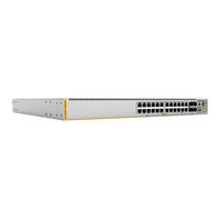
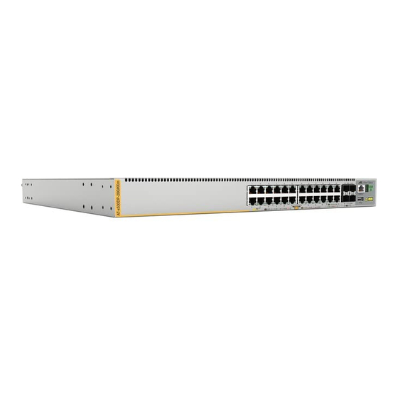
Allied Telesis x530DP Series Installation Manual (214 pages)
Stackable Gigabit Layer 3+ Ethernet Switches AlliedWare Plus v5.5.1-2.1
Brand:
Allied Telesis
| Category:
Switch
| Size: 13.14 MB
Table of Contents
Table of Contents
5
Preface
13
Document Conventions
14
Contacting Allied Telesis
15
Chapter 1: Overview
17
Front and Rear Panels
18
Figure 1: Front Panel of the X530Dp-28Ghxm Switch
18
Figure 2: Front Panel of the X530Dp-52Ghxm Switch
18
Figure 3: Back Panel of the X530Dp Series Switch
18
Management Panel
19
Figure 4: Management Panel
19
Features
20
X530Dp Models
20
Twisted Pair Ports
20
Table 1: Basic Features
20
Power over Ethernet
21
SFP+ Transceiver Ports
21
Leds
22
Installation Options
22
Management Software and Interfaces
23
Management Methods
23
Power Supplies
24
Non-Poe Power Supplies
24
System and Poe Power Supplies
25
Figure 5: Non-Poe Power Supplies
25
General Guidelines
26
Figure 6: System and Poe Power Supplies
26
Table 2: System and Poe Power Supply Summary
26
FAN10 and FAN10R Cooling Fans
28
Figure 7: FAN10 and FAN10R Fan Modules
28
Twisted Pair Ports
29
Table 3: X530Dp-28Ghxm Switch Twisted Pair Port Specifications
29
Speed
30
Table 4: X530Dp-52Ghxm Switch Twisted Pair Port Specifications
30
Duplex Mode
31
Wiring Configuration
31
Maximum Distance
31
Cable Requirements
32
Port Pinouts
32
Leds
32
Figure 8: X530Dp-28Ghxm Twisted Pair Ports1-24 Leds
32
Table 5: X530Dp-28Ghxm Twisted Pair Ports 1 - 24 LED Functions
33
Figure 9: X530Dp-52Ghxm Twisted Pair Ports 1-48 Leds
34
Table 6: X530Dp-52Ghxm Twisted Pair Ports 1 - 48 LED Functions
34
Power over Ethernet
36
Poe Standards
36
Powered Device Classes
37
Power Budget
37
Table 7: IEEE Powered Device Classes
37
Table 8: Power Supply Budgets of the Power Supplies
37
Table 9: Power Budgets of the PWR800 Power Supply
38
Table 10: Power Budgets of the PWR1200 Power Supply
38
Port Prioritization
39
Wiring Implementation
40
SFP+ Transceiver Ports
41
SFP and SFP+ Transceivers
41
Leds
41
Figure 10: Link and Activity Leds for the 1Gbps Sfp/10Gbps SFP+ Ports
41
Table 11: Link and Activity Status Leds for the 1Gbps and 10Gbps Ports
42
Eco-Friendly Button
43
Vcstack Feature
44
Switch ID LED
45
Figure 11: Switch ID LED
45
Figure 12: Switch ID LED Description
46
USB Port
47
Console Port
48
Chapter 2: Virtual Chassis Stacking
49
Overview
50
Stacking Guidelines
51
Stack Trunks
53
Table 12: Default (10Gbps) and Optional (5Gbps) Trunk Ports
53
Stack Trunks of SFP+ 10Gbps Ports
54
Figure 13: Stack Trunks Using the Default Stacking SFP+ Ports
55
Figure 14: Stack Trunks Using SFP+ Ports
56
Figure 15: 10Gbps Stack Trunk with both SFP+ Fiber Optic Transceivers and SP10TW Direct Connect Cables
57
Stack Trunks of 5Gbps Twisted Pair Ports
58
Figure 16: Trunks of 5Gbps Ports for Stacks of Two Switches
59
Figure 17: Trunks of 5Gbps Ports for Stacks of Three Switches
60
Figure 18: Trunks of 5Gbps Ports for Stacks of Four Switches
61
Invalid Stack Trunks
62
Example 1
62
Example 2
62
Figure 19: Invalid Stack Trunk with an Intermediary Networking Device
62
Figure 20: Invalid Stack Trunk with One Port Used Per Switch
62
Example 3
63
Example 4
63
Figure 21: Invalid Stack Trunk with Different Numbers of Links
63
Figure 22: Invalid Stack Trunk with Different Port Types
63
Master and Member Switches
64
Selection of the Master Switch
64
Switch ID Numbers
66
Optional Feature Licenses
67
Mixed Switch Stacks
68
Stack Mixed-Mode Licenses
68
Stack Mixed-Mode Commands
69
Trunk Ports
69
Optional Licenses
69
Alliedware Plus
69
Guidelines
69
Planning the Stack
71
Configuring Mixed-Mode Vcstacking
72
Stacking Worksheet
73
Table 13: Stacking Worksheet
73
Table 14: Stacking Worksheet Columns
74
Chapter 3: Beginning the Installation
77
Reviewing Safety Precautions
78
Choosing a Site for the Switch
83
Installation Options
84
Figure 23: Installation Options
84
Unpacking the Switch
85
Figure 24: Switch Shipping Box
85
Verifying the Accessory Kit
86
Figure 25: Accessory Kit
86
Unpacking the Power Supply
88
Chapter 4: Installing the Power Supplies
89
Installing the Power Supplies
90
Figure 26: Removing the PNL800/1200 Blank Panel
91
Figure 27: Power Supply Accessory Items
92
Table 15: Accessory Items Included with a Power Supply
92
Figure 28: Installing a Power Supply
93
Figure 29: Improper Installation of a Power Supply
94
Figure 30: Tightening the Captive Screws on the Power Supply
94
Figure 31: Installing the Power Cord Retaining Clip
95
Installing a Blank Power Supply Slot Cover
96
Figure 32: Installing a Blank Panel on a Power Supply Slot
96
Figure 33: Tightening the Captive Screws on the Power Supply Blank Panel
97
Chapter 5: Installing the Switch on a Table
99
Installing the Rubber Feet on the Switch
100
Placing the Switch on a Desk or Table
101
Chapter 6: Installing the Switch in an Equipment Rack
103
Installing the Switch in an Equipment Rack
104
Required Items
104
Switch Orientations in the Equipment Rack
104
Figure 34: Bracket Holes on the Switch
104
Installing the Switch
105
Figure 35: Switch Orientations in an Equipment Rack
105
Figure 36: Example of Attaching the Brackets to the Switch
106
Figure 37: Installing the Switch in an Equipment Rack
107
Chapter 7: Installing the Switch on a Wall
109
Switch Orientations on a Wall
110
Figure 38: Positioning the Switch on the Wall
110
Installation Guidelines
111
Tools and Material
112
Plywood Base for a Wall with Wooden Studs
113
Figure 39: Switch on the Wall with Plywood Base
113
Installing a Plywood Base to the Wall
114
Figure 40: Installing the Plywood Base to the Wall
114
Installing the Switch on a Plywood Base
115
Figure 41: Installing Brackets on the Switch
115
Figure 42: Securing the Switch to the Plywood Base
116
Installing the Switch on a Concrete Wall
117
Figure 43: Marking the Locations of the Bracket Holes on a Concrete Wall
118
Figure 44: Installing the Switch on a Concrete Wall
119
Chapter 8: Wiring the DC Connector on the PWR250-80 Power Supply
121
Figure 45: On/Off Switch on PWR250-80 Power Supply
122
Figure 46: DC Terminal Block
122
Figure 47: Stripped Wire
123
Figure 48: Connecting the Ground Wire to the DC Terminal Block
124
Chapter 9: Building the Stack Trunk with 5Gbps Multi-Speed Ports
127
Introduction
128
Command Summary
130
Stackport
130
Stack Enable
131
Stack Priority
131
Stack Renumber
132
Switch Provision
132
Configuring the Master Switch
133
General Steps for the Master Switch
133
Configuring the Master Switch - Part I
134
Table 16: Configuring the Master Switch for 5Gbps Stacking Ports - Part I
134
Configuring the Master Switch - Part II
137
Table 17: Configuring the Master Switch for 5Gbps Stacking Ports - Part II
138
Verifying the Master Switch
139
Table 18: Verifying the Master Switch
139
What to Do Next
140
Figure 49: Powering off the Switch
140
Configuring Member Switches
142
General Steps for the Member Switch
142
Configuring Member Switches - Part I
143
Table 19: Configuring Member Switches - Part I
143
Configuring Member Switches - Part II
145
Table 20: Configuring Member Switches - Part II
146
Verifying Member Switches
147
Table 21: Verifying Member Switches
147
What to Do Next
148
Powering on the Stack
150
Verifying the Stack
151
Figure 50: SHOW STACK Command
151
Chapter 10: Cabling the Networking Ports
153
Cabling Twisted Pair Ports
154
Guidelines to Handling SFP and SFP+ Transceivers
155
Installing SFP or SFP+ Transceivers
156
Figure 51: Installing an SFP Transceiver
156
Figure 52: Positioning the SFP or SFP+ Handle in the up Position
157
Figure 53: Connecting a Fiber Optic Cable to an SFP or SFP+ Transceiver
157
Installing SP10TW Direct Connect Twinax Cables
158
Figure 54: Installing SP10TW Cables
159
Chapter 11: Troubleshooting
161
Appendix A: Technical Specifications
165
Physical Specifications
166
Table 22: Product Dimensions
166
Figure 55: X530Dp-28Ghxm and X530Dp-52Ghxm Switch Dimensions
167
Figure 56: FAN10 Dimensions
167
Table 23: Product Weights
168
Table 24: Ventilation Requirements
168
Environmental Specifications
169
Table 25: Environmental Specifications
169
Table 26: Maximum Operating Temperature
169
Power Specifications
170
Table 27: Maximum Power Consumptions with the PWR150, PWR250, or PWR250-80 Power Supply
170
Table 28: Maximum Power Consumptions with the PWR800 or PWR1200 Power Supply
170
Table 29: Input Voltages
170
Table 30: Maximum Heat Dissipation with the PWR150, PWR250, or PWR250-80 Power Supply
171
Table 31: Maximum Heat Dissipation with the PWR800 or PWR1200 Power Supply
171
Certifications
172
Table 32: Product Certifications
172
Twisted Pair Port Pinouts
173
Figure 57: RJ-45 Socket Pin Layout (Front View)
173
Table 33: Pin Signals for 10/100M and 2.5G/5G Base-T Connectors
173
Style Serial Console Port Pinouts
174
Table 34: RJ-45 Style Serial Console Port Pin Signals
174
USB Port
175
Table 35: USB Port Pin Signals
175
Appendix B: Installing the Switch in the RKMT-SL01 Sliding Rack
177
Introduction
178
Rack Mount Kit Components
179
Adjustable Outer Rails
179
Inner Rails
179
Figure 58: Outer Rails
179
Figure 59: Inner Rails
179
Extension Brackets
180
Figure 60: Extension Brackets
180
Equipment Rack Requirements
181
Reviewing Safety Precautions
182
Installation Overview
185
Unpacking the Shipping Container
186
Figure 61: Shipping Container Contents
186
Installing the Outer Rails on the Equipment Rack
188
Figure 62: FRONT and REAR Labels on the Outer Rails
188
Figure 63: Installing the Outer Rails on the Equipment Rack
189
Installing the Extension Brackets on the Inner Rails
190
Measuring the Extension Bracket Lengths
190
Figure 64: Extension Brackets
190
Figure 65: Example of a Switch Recessed in an Equipment Rack
190
Figure 66: Inserting an Inner Rail into an Outer Rail
191
Figure 67: Example of Positioning the Inner Rail
191
Figure 68: Measuring for the Extension Brackets
191
Assembling the Extension Brackets
192
Figure 69: Removing the Inner Rail
192
Figure 70: Extension Bracket Parts
192
Table 36: Extension Bracket Parts
192
Figure 71: Extension Bracket Configurations
193
Figure 72: Example of Attaching the Extension Brackets to the Inner Rails
194
Figure 73: Testing the Inner Rails with the Extension Brackets
195
Figure 74: Verifying the Length of the Extension Bracket
195
Installing the Inner Rails on the Switch
196
Figure 75: Inner Rail Screw Holes for the X530Dp-28Ghxm Switch
196
Figure 76: Attaching the Inner Rails to the X530Dp-28Ghxm Switch
196
Installing the Switch in the Equipment Rack
197
Figure 77: Sliding the Inner Rails on the Switch into the Outer Rails
197
Figure 78: Affixing the Warning Labels
198
Figure 79: Tightening the Two Screws on the Fixed Brackets
198
Figure 80: Tightening the Screws on the Outer Rails
199
Appendix C: Removing Modules
201
Removing AC Power Supplies
202
Figure 81: Lifting the Power Cord Restraining Clip
202
Figure 82: Disconnecting the Power Cord from the Power Supply
203
Figure 83: Loosening the Two Captive Screws
203
Figure 84: Removing a Power Supply
204
Removing the PWR250-80 DC Power Supply
205
Figure 85: On/Off Switch on PWR250-80 Power Supply
206
Figure 86: DC Terminal Block
206
Figure 87: Disconnecting the Ground Wire to the DC Terminal Block
207
Figure 88: Loosening the Two Captive Screws
207
Figure 89: Removing a Power Supply
208
Installing a Blank Power Supply Slot Cover
209
Figure 90: Installing a Blank Panel on a Power Supply Slot
209
Figure 91: Tightening the Captive Screws on the Power Supply Blank Panel
210
Removing and Replacing the FAN10 or FAN10R Module
211
Removing the Fan Module
211
Figure 92: Loosening the Screws on the FAN10 / FAN10R Module
211
Installing the Fan Module
212
Figure 93: Removing the FAN10 / FAN10R Module from the Switch
212
Figure 94: Aligning the FAN10 / FAN10R Module in the Switch Slot
212
Figure 95: Seating the FAN10 / FAN10R Module on the Internal Connector
213
Figure 96: Tightening the Two Captive Screws on the FAN10 / FAN10R Module
213
Ence for X530 Series Switches Running Alliedware Plus at Www.alliedtelesis.com.reverse Airflow Combinations
214
Guidelines
214
Advertisement
Advertisement
Related Products
Allied Telesis x530DP-28GHXm
Allied Telesis x530DP-52GHXm
Allied Telesis x530 Series
Allied Telesis x530-28GPXm
Allied Telesis x530L-10GHXm
Allied Telesis x530L-18GHXm
Allied Telesis x530L-28GTX
Allied Telesis x530L-52GPX
Allied Telesis x530-10GHXm
Allied Telesis x530-28GSX
Allied Telesis Categories
Switch
Network Router
Media Converter
Network Hardware
Wireless Access Point
More Allied Telesis Manuals
Login
Sign In
OR
Sign in with Facebook
Sign in with Google
Upload manual
Upload from disk
Upload from URL