Allied Telesis x530 Series Installation Manual
Stackable gigabit layer 3 ethernet switches
Hide thumbs
Also See for x530 Series:
- Installation manual (128 pages) ,
- Quick installation manual (24 pages)
Table of Contents
Advertisement
Quick Links
x530 Series
Stackable Gigabit Layer 3 Ethernet Switches
AlliedWare Plus™ v5.5.2-2
x530-10GHXm
x530-18GHXm
x530-28GTXm
x530-28GPXm
x530-28GSX
x530-52GTXm
x530-52GPXm
1
3
5
7
9
11
2
4
6
8
10
12
PORTS 1-40
1G LINK
Installation Guide for Virtual Chassis
Stacking
613-002668 Rev. G
1
2
PORTS 1-20
1G LINK
ACT
100 LINK
13
15
17
19
21
23
25
14
16
18
20
22
24
26
PORTS 41-48
ACT
100 LINK
ACT
5G/2.5G/1G LINK
ACT
100 LINK
ACT
PD ON
5G/2.5G/1G LINK
100 LINK
ACT
ACT
1
3
5
7
2
4
6
8
5G/2.5G/1G LINK
ACT
100 LINK
ACT
3
5
7
9
11
13
15
4
6
8
10
12
14
16
PORTS 21-24
ACT
5G/2.5G/1G LINK
ACT
100 LINK
ACT
PD ON
PD ERR
27
29
31
33
35
37
39
28
30
32
34
36
38
40
PD ERR
MAX CURRENT
1
3
5
7
9/S1
SFP+
CONSOLE
2
4
6
8
10/S2
PD ON
PD ERR
MAX CURRENT
10G/1G
9
11
13
15
17/S1
SFP+
CONSOLE
10
12
14
16
18/S2
PD ON
PD ERR
MAX CURRENT
10G/1G
17
19
21
23
25
SFP+
27/S1
CONSOLE
18
20
22
24
26
10G/1G
28/S2
MAX CURRENT
5G/2.5G/1G/100
41
43
45
47
49
SFP+
51/S1
CONSOLE
42
44
46
48
50
10G/1G
52/S2
5G/2.5G/1G/100
CLASS 1
LASER PRODUCT
CLASS 1
LASER PRODUCT
CLASS 1
LASER PRODUCT
CLASS 1
LASER PRODUCT
Advertisement
Table of Contents

Related Manuals for Allied Telesis x530 Series


Summary of Contents for Allied Telesis x530 Series
- Page 1 Series Stackable Gigabit Layer 3 Ethernet Switches AlliedWare Plus™ v5.5.2-2 x530-10GHXm x530-18GHXm x530-28GTXm x530-28GPXm x530-28GSX x530-52GTXm x530-52GPXm 9/S1 SFP+ CONSOLE CLASS 1 LASER PRODUCT 10/S2 5G/2.5G/1G LINK 100 LINK PD ON PD ERR MAX CURRENT 10G/1G 17/S1 SFP+ CONSOLE...
- Page 2 Allied Telesis, Inc. has been advised of, known, or should have known, the...
- Page 3 Electrical Safety and Emissions Standards This product meets the following standards. U.S. Federal Communications Commission Radiated Energy Note: This equipment has been tested and found to comply with the limits for a Class A digital device pursuant to Part 15 of FCC Rules.
- Page 4 Translated Safety Statements Important: Safety statements that have the symbol are translated into multiple languages in the Translated Safety Statements document at https://www.alliedtelesis.com/us/en/documents/ translated-safety-statements. Remarque: Les consignes de sécurité portant le symbole sont traduites dans plusieurs langues dans le document Translated Safety Statements, disponible à l'adresse https:// www.alliedtelesis.com/us/en/documents/translated-safety-statements.
-
Page 5: Table Of Contents
Contents Preface: .....................................13 Document Conventions ...............................14 Contacting Allied Telesis ..............................15 Chapter 1: Overview ................................ 17 Front and Rear Panels ................................18 Features ....................................21 x530 Models .................................21 Power Over Ethernet ..............................22 SFP/SFP+ Transceiver Ports ............................23 LEDs.....................................24 Installation Options ...............................24 Management Software and Interfaces .........................24 Management Methods..............................25... - Page 6 Contents Example 4..................................77 Master and Member Switches ............................78 Selection of the Master Switch ............................ 78 Switch ID Numbers ................................80 Optional Feature Licenses ..............................81 Mixed Switch Stacks ................................82 Stack Mixed-Mode Licenses............................82 Stack Mixed-Mode Commands............................ 83 Trunk Ports ..................................
- Page 7 Series Installation Guide for Virtual Chassis Stacking Configuring the Master Switch - Part I........................156 Configuring the Master Switch - Part II........................158 Verifying the Master Switch ............................160 What to Do Next .................................162 Configuring Member Switches............................163 General Steps for the Member Switch........................163 Configuring Member Switches - Part I........................164...
- Page 8 Contents...
- Page 9 Figures Figure 1: Front Panel of the x530-10GHXm Switch......................18 Figure 2: Front Panel of the x530-18GHXm Switch......................18 Figure 3: Front Panel of the x530-28GTXm Switch ......................18 Figure 4: Front Panel of the x530-28GPXm Switch......................19 Figure 5: Front Panel of the x530-28GSX Switch.........................19 Figure 6: Front Panel of the x530-52GTXm Switch ......................19 Figure 7: Front Panel of the x530-52GPXm Switch......................20 Figure 8: Back Panel of the x530-10GHXm, x530-18GHXm, x530-28GPXm, and x530-52GPXm PoE Switches ....20...
- Page 10 Figures Figure 48: Securing the x530-28GTXm or x530-28GSX Switch to the Plywood Base ............125 Figure 49: Securing the x530-10GHXm, x530-18GHXm, x530-28GPXm, x530-52GTXm or x530-52GPXm Switch to the Plywood Base..........................126 Figure 50: Marking the Locations of the Bracket Holes on a Concrete Wall...............128 Figure 51: Installing the Switch on a Concrete Wall ......................129 Figure 52: Management Cable Included with Switch......................138 Figure 53: VT-Kit3 Management Cable ..........................138...
- Page 11 Tables Table 1: Basic Features ...............................21 Table 2: Copper Port Features ............................27 Table 3: x530-10GHXm Switch Copper Port Specifications ....................28 Table 4: x530-18GHXm Switch Copper Port Specifications ....................29 Table 5: x530-28GTXm Switch Copper Port Specifications ....................30 Table 6: x530-28GPXm Switch Copper Port Specifications ....................31 Table 7: x530-52GTXm Switch Copper Port Specifications ....................32 Table 8: x530-52GPXm Switch Copper Port Specifications ....................33 Table 9: IEEE Powered Device Classes ..........................36...
- Page 12 Tables...
-
Page 13: Preface
Preface This guide contains the installation instructions for the x530 Series of stackable Gigabit, Layer 3 Ethernet switches. This preface contains the following sections: “Document Conventions” on page 14 “Contacting Allied Telesis” on page 15 Note This guide explains how to install switches as a stack with Virtual ™... -
Page 14: Document Conventions
Preface Document Conventions This document uses the following conventions: Note Notes provide additional information. Caution Cautions inform you that performing or omitting a specific action may result in equipment damage or loss of data. Warning Warnings inform you that performing or omitting a specific action may result in bodily injury. -
Page 15: Contacting Allied Telesis
guides, software release notes, white papers and data sheets for your product. Warranty - View a list of products to see if Allied Telesis warranty applies to the product you purchased and register your warranty. To contact a sales representative or find Allied Telesis office locations, go... - Page 16 Preface...
-
Page 17: Chapter 1: Overview
Note This guide explains how to install switches as a stack with Virtual ™ Chassis Stacking (VCStack ). For instructions on how to install the devices as standalone switches, refer to the x530 Series Installation Guide for Standalone Switches. -
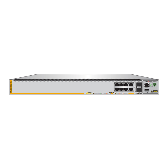
Page 18: Front And Rear Panels
Chapter 1: Overview Front and Rear Panels The front panels on the x530 Series switches are shown in Figure 1 through Figure 7 on page 20. 9/S1 SFP+ CONSOLE CLASS 1 LASER PRODUCT 10/S2 5G/2.5G/1G LINK 100 LINK PD ON... -
Page 19: Figure 4: Front Panel Of The X530-28Gpxm Switch
Series Installation Guide for Virtual Chassis Stacking SFP+ 27/S1 CONSOLE CLASS 1 LASER PRODUCT 10G/1G 28/S2 PORTS 1-20 PORTS 21-24 1G LINK 100 LINK 5G/2.5G/1G LINK 100 LINK PD ON PD ERR MAX CURRENT 5G/2.5G/1G/100 POE+ Ports 1-24 4563... -
Page 20: Figure 7: Front Panel Of The X530-52Gpxm Switch
Panel Ports 41-48 10Gbps SFP+/1Gbps SFP Transceiver Ports 49-52 Figure 7. Front Panel of the x530-52GPXm Switch The back panels of the x530 Series switches are shown in Figure 8 and Figure 9. PSU 2 PSU 1 100-240 VAC~ 100-240 VAC~... -
Page 21: Features
Series Installation Guide for Virtual Chassis Stacking Features The Allied Telesis x530 Series switches are stackable Gigabit, Layer 3 Ethernet switches. The following sections list the features. x530 Models Table 1 lists the basic features for each switch model. -
Page 22: Power Over Ethernet
Chapter 1: Overview Power Over The basic features of PoE+ on the copper ports of the x530-28GPXm and x530-52GPXm switches are: Ethernet Supported on all ports. Supports PoE (15.4W maximum) and PoE+ (30W maximum) powered devices 740W maximum power budget (370W per power supply) ... -
Page 23: Sfp/Sfp+ Transceiver Ports
Series Installation Guide for Virtual Chassis Stacking SFP/SFP+ The SFP transceivers slots (ports 1 to 24) on the x530-28GSX switch support the following types of transceivers: Transceiver Ports 100Mbps/1Gbps SFP transceivers The four SFP+ transceiver slots in the x530-28GTXm, x530-28GPXm, and... -
Page 24: Leds
Chapter 1: Overview Note The switches do not support the 7-meter AT-SP10TW7 direct attach cable. Note For a current list of supported transceiver modules refer to the x530 Series Data Sheet. The following restrictions on SFP+ transceivers apply: 100Mbps transceivers are not supported ... -
Page 25: Management Methods
Series Installation Guide for Virtual Chassis Stacking Management The following methods are used for managing the switches: Methods Local management through the Console port Remote Telnet or Secure Shell management Vista Manager mini Autonomous Management Framework (AMF) with Vista ... -
Page 26: Management Panel
Chapter 1: Overview Management Panel Figure 10 identifies the components on the management panel. Switch ID LED Console Management eco-friendly Port Button CONSOLE Port CLASS 1 LASER PRODUCT 4567 Figure 10. Management Panel... -
Page 27: Copper Ports
Series Installation Guide for Virtual Chassis Stacking Copper Ports Table 2 lists the copper ports features for each switch model. Table 2. Copper Port Features x530- x530- x530- x530- x530- x530- Feature 10GHXm 18GHXm 28GTXm 28GPXm 52GTXm 52GPXm (PoE++) -
Page 28: Table 3: X530-10Ghxm Switch Copper Port Specifications
Chapter 1: Overview The specifications of the copper ports are listed in: Table 3 for the x530-10GHXm switch, next Table 4 on page 29 for the x530-18GHXm switch Table 5 on page 30 for the x530-28GTXm switch Table 6 on page 31 for the x530-28GPXm switch ... -
Page 29: Table 4: X530-18Ghxm Switch Copper Port Specifications
Series Installation Guide for Virtual Chassis Stacking Table 4. x530-18GHXm Switch Copper Port Specifications Specification Description Port Speed Ports 1 - 16: 100Mbps or 1/2.5/5Gbps. 100Mbps: Set the port speed manually or with Auto-Negotiation. 1/2.5/5Gbps: The port speed is set with Auto- Negotiation only. -
Page 30: Table 5: X530-28Gtxm Switch Copper Port Specifications
Chapter 1: Overview Table 5. x530-28GTXm Switch Copper Port Specifications Specification Description Port Speed Ports 1 - 20: 10Mbps/100Mbps/1000Mbps. Ports 21 - 24: 100Mbps or 1/2.5/5Gbps Ports 1 - 20: Set the port speed manually or with Auto-Negotiation at 10Mbps and 100Mbps. -
Page 31: Table 6: X530-28Gpxm Switch Copper Port Specifications
Series Installation Guide for Virtual Chassis Stacking Table 6. x530-28GPXm Switch Copper Port Specifications Specification Description Port Speed Ports 1 - 20: 10Mbps/100Mbps/1000Mbps. Ports 21 - 24: 100Mbps or 1/2.5/5Gbps Ports 1 - 20: Set the port speed manually or with Auto-Negotiation at 10Mbps and 100Mbps. -
Page 32: Table 7: X530-52Gtxm Switch Copper Port Specifications
Chapter 1: Overview Table 7. x530-52GTXm Switch Copper Port Specifications Specification Description Port Speed Ports 1 - 40: 10Mbps/100Mbps/1000Mbps. Ports 41 - 48: 100Mbps or 1/2.5/5Gbps Ports 1 - 40: Set the port speed manually or with Auto-Negotiation at 10Mbps, and 100Mbps. -
Page 33: Duplex Mode
Series Installation Guide for Virtual Chassis Stacking Table 8. x530-52GPXm Switch Copper Port Specifications Specification Description Port Speed Ports 1 - 40: 10Mbps/100Mbps/1000Mbps. Ports 41 - 48: 100Mbps or 1/2.5/5Gbps Ports 1 - 40: Set the port speed manually or with Auto-Negotiation at 10Mbps, and 100Mbps. -
Page 34: Wiring Configuration
Chapter 1: Overview Note Switch ports default to half-duplex mode when connected to 10Mbps or 100Mbps network devices that do not support Auto-Negotiation. If a network device supports full-duplex only, a duplex mode mismatch can occur, resulting in poor network performance. To prevent this, disable Auto-Negotiation and set the duplex mode manually on ports connected to 10Mbps or 100Mbps devices that support full-duplex only. -
Page 35: Power Over Ethernet
Series Installation Guide for Virtual Chassis Stacking Power Over Ethernet The x530-10GHXm, x530-18GHXm, x530-28GPXm and x530-52GPXm switches feature PoE on copper ports. With PoE, the switches supply DC power to network devices over the same copper cables that carry the network traffic. -
Page 36: Powered Device Classes
Chapter 1: Overview Powered Device Powered devices are grouped into the nine classes listed in Table 9. The classes are based on the amount of power the devices require. The x530- Classes 28GPXm and x530-52GPXm switches support classes 0 to 4. The x530- 10GHXm and x530-18GHXm switches support classes 0 to 8. -
Page 37: Port Prioritization
Series Installation Guide for Virtual Chassis Stacking x530-10GHXm switch can support Class 8 power devices on all eight of its copper ports, while the x530-18GHXm switch can support up to eleven Class 8 devices. Port The power requirements of the PoE devices determine the maximum number of devices the switch can support at one time. -
Page 38: Wiring Implementation
Chapter 1: Overview Power allocation is dynamic. Ports supplying power to powered devices can cease power transmission if the switch power budget is at maximum usage and new powered devices, connected to ports with higher priorities become active. Wiring The IEEE 802.3af standard defines two methods for delivering DC power over copper cable by a switch to powered devices. -
Page 39: Eco-Friendly Button
Series Installation Guide for Virtual Chassis Stacking eco-friendly Button The eco-friendly button on the front panel of the switch is used to toggle the port LEDs on or off. You can turn off the LEDs to conserve electricity when you are not monitoring the device. You can also toggle the LEDs... -
Page 40: Leds
Chapter 1: Overview LEDs Each copper port has two LEDs that display the port status. x530-10GHXm The LEDs indicate Link/Activity (L/A) and PoE (PD ON/PD ERR/MAX CURRENT) information. These LEDs are shown in Figure 11. L/A LED PoE LED Figure 11. x530-10GHXm Copper Ports The states of the x530-10GHXm LEDs are described in Table 10. -
Page 41: Figure 12: X530-18Ghxm Copper Ports
Series Installation Guide for Virtual Chassis Stacking Table 10. x530-10GHXm Copper Ports 1 - 8 LED Functions (Continued) Ports State Description Solid Green PD On - The switch is delivering power to a powered device connected to the port. -
Page 42: Table 11: X530-18Ghxm Copper Ports 1 - 16 Led Functions
Chapter 1: Overview Table 11. x530-18GHXm Copper Ports 1 - 16 LED Functions Ports State Description Solid Green The port has established a 1/2.5/5Gbps link to a network device. Flashing The port is transmitting or receiving data at 1/2.5/ Green 5Gbps. -
Page 43: Figure 13: X530-28Gtxm And X530-52Gtxm Copper Ports Leds
Series Installation Guide for Virtual Chassis Stacking x530-28GTXm and x530-52GTXm The x530-28GTXm and x530-52GTXm LEDs indicate Link/Activity (L/A) and Duplex/Collision (FDX/HDX/COL) information. These LEDs are shown in Figure 13. L/A LED D/C LED Figure 13. x530-28GTXm and x530-52GTXm Copper Ports LEDs The states of the x530-28GTXm LEDs are described in Table 12. -
Page 44: Table 13: X530-52Gtxm Copper Ports 1 - 48 Led Functions
Chapter 1: Overview Table 12. x530-28GTXm Copper Ports 1 - 24 LED Functions (Continued) Ports State Description Solid Green The port is operating in full-duplex mode. Solid Amber The port is operating in half-duplex mode. 1 - 24 Flashing Amber The port is operating in half-duplex mode with collisions. -
Page 45: Figure 14: X530-28Gpxm And X530-52Gpxm Copper Ports Leds
Series Installation Guide for Virtual Chassis Stacking Table 13. x530-52GTXm Copper Ports 1 - 48 LED Functions (Continued) Ports State Description Solid Green The port is operating in full-duplex mode. Solid Amber The port is operating in half-duplex mode. -
Page 46: Table 14: X530-28Gpxm Copper Ports 1 - 24 Led Functions
Chapter 1: Overview The states of the x530-28GPXm LEDs are described in Table 14. Table 14. x530-28GPXm Copper Ports 1 - 24 LED Functions Ports State Description Solid Green The port has established a 1Gbps link to a network device. Flashing The port is transmitting or receiving data at 1Gbps. - Page 47 Series Installation Guide for Virtual Chassis Stacking Table 14. x530-28GPXm Copper Ports 1 - 24 LED Functions (Continued) Ports State Description Solid Green PD On - The switch is delivering power to a powered device on the port. Solid Amber PD Error - The switch has shut down PoE on the port because of a fault condition.
-
Page 48: Table 15: X530-52Gpxm Copper Ports 1 - 48 Led Functions
Chapter 1: Overview The states of the x530-52GPXm LEDs are described in Table 15. Table 15. x530-52GPXm Copper Ports 1 - 48 LED Functions Ports State Description Solid Green The port has established a 1Gbps link to a network device. Flashing The port is transmitting or receiving data at 1Gbps. -
Page 49: Leds For The Sfp Ports
Series Installation Guide for Virtual Chassis Stacking Table 15. x530-52GPXm Copper Ports 1 - 48 LED Functions (Continued) Ports State Description Solid Green PD On - The switch is delivering power to a powered device connected to the port. -
Page 50: S1 And S2 Sfp+ Port Leds
Chapter 1: Overview The states of the x530-28GSX LEDs are described in Table 16. Table 16. x530-28GSX SFP Network / Stacking LEDs Ports State Description Solid Green The port has established at 1Gbps link to a network device. Flashing Green The port is transmitting or receiving data at 1Gbps. -
Page 51: Figure 16: Link And Activity Leds For The 1Gbps/10Gbps Sfp+ Ports
Series Installation Guide for Virtual Chassis Stacking Here are the S1 and S2 ports on the switches: x530-10GHXm switch - ports 9/S1 - 10/S2 x530-18GHXm switch - ports 17/S1 - 18/S2 x530-28GPXm, x530-28GTXm, and x530-28GSX switches - ports ... -
Page 52: Switch Id Led
Chapter 1: Overview The LEDs display link status and activity. The possible LED states are described in Table 17. Table 17. Link and Activity Status LEDs for the 1Gbps and 10Gbps Ports State Description Solid Green The transceiver has established a 10Gbps link to a network device. -
Page 53: Figure 18: Switch Id Led Description
Series Installation Guide for Virtual Chassis Stacking The states of the LED when the switch is not operating in the low power mode are shown in Figure 18. The switch is booting up. The switch has encountered a fault condition. -
Page 54: Vcstack Feature
Note This guide explains how to install switches as a stack with Virtual ™ Chassis Stacking (VCStack ). For instructions on how to install the devices as standalone switches, refer to the x530 Series Installation Guide for Standalone Switches. -
Page 55: Usb Port
Series Installation Guide for Virtual Chassis Stacking USB Port The USB port on the management panel is used for the following functions: Store configuration files on flash drives. Restore configuration files to switches that have lost or corrupted ... -
Page 56: Console Port
Chapter 1: Overview Console Port The Console port is an RS232 serial management port. You use the port to access the AlliedWare Plus management software on the switch to configure the feature settings or monitor status or statistics. This type of management is commonly referred to as local management because you have to be at the physical location of the switch and use the management cable included with the unit. -
Page 57: Power Supplies
Series Installation Guide for Virtual Chassis Stacking Power Supplies The x530 Series switches come with dual pre-installed AC power supplies. Refer to “Power Specifications” on page 195 for the input voltage ranges. Warning The power cord is used as a disconnection device. To de-energize equipment, disconnect the power cord. -
Page 58: Software And Hardware Releases
Chapter 1: Overview Software and Hardware Releases Software and hardware releases for the AlliedWare Plus operating software and x530 Series switches are listed in Table 18. Table 18. Software and Hardware Releases Software Hardware VCStack Version v5.4.8-2 x530-28GPXm switch Allows stacks of up to eight... -
Page 59: Chapter 2: Virtual Chassis Stacking
“Configuring Mixed-Mode VCStacking” on page 86 “Stacking Worksheet” on page 87 Note For more information on VCStack, refer to the Stacking Introduction and Stacking Commands chapters in the Command Reference: x530 Series Switches Running AlliedWare Plus Version 5.5.0 at www.alliedtelesis.com/library. -
Page 60: Overview
Chapter 2: Virtual Chassis Stacking Overview The VCStack feature is used to connect multiple x530 Series switches into a single, virtual networking unit. Some of the benefits of the VCStack feature are listed here: Simplifies management - You can manage the devices of the stack ... -
Page 61: Stacking Guidelines
You must connect the switches of a stack together with a trunk, consisting of a minimum of two ports per switch. Here are the ports that you can use as trunk ports on x530 Series switches: – SFP+ ports with 10Gbps transceivers or direct connect cables –... - Page 62 – Maximum eight ports per switch for trunks of 1Gbps SFP ports 1 to 24 on the x530-28GSX Switch The default trunk ports on the x530 Series switches are the last two SFP+ ports: – Ports 9/S1 and 10/S2 on the x530-10GHXm Switch –...
-
Page 63: Stack Trunks
Series Installation Guide for Virtual Chassis Stacking Stack Trunks Stack trunks connect the switches of a stack together. A stack trunk consists of a minimum of two ports on each device. For switches with AlliedWare Plus v5.5.1-1.2 or later, you can choose the ports of the trunk. -
Page 64: Stack Trunks Of The Default 10Gbps Sfp+ S1 And S2 Stacking Ports
SFP+ transceivers must be from Allied Telesis and be approved for use in the product. For a list of supported 10Gbps SFP+ transceivers, refer to the product data sheet on the Allied Telesis web site. Note Transceivers are purchased separately. -
Page 65: Figure 19: Stack Trunks Of Default S1 And S2 Ports
Series Installation Guide for Virtual Chassis Stacking Figure 19 shows examples of stack trunks for two, three and four switches, using the x530-28GTXm default stacking ports S1 and S2. 27/S1 SFP+ 27/S1 CONSOLE CLASS 1 LASER PRODUCT 28/S2 28/S2... - Page 66 Chapter 2: Virtual Chassis Stacking In stacks of three or more switches the amount of inter-switch network traffic might require a stacking trunk with greater bandwidth than that provided by the default ports of: x530-28GTXm, x530-28GSX, and x530-28GPXm ports 27/S1 and ...
-
Page 67: Figure 20: Stack Trunks Using All Four Ports
Series Installation Guide for Virtual Chassis Stacking Figure 20 shows examples of stacks of three and four switches using all four SFP+ ports for the stack trunk. SFP+ 27/S1 CONSOLE CLASS 1 LASER PRODUCT 10G/1G 28/S2 5G/2.5G/1G LINK PORTS 1-20... -
Page 68: Figure 21: 10Gbps Stack Trunk With Both Sfp+ Fiber Optic Transceivers And Sp10Tw Direct Connect Cables
Chapter 2: Virtual Chassis Stacking 10Gbps stack trunks can have both fiber optic transceivers and SP10TW direct attach cables. The example in Figure 21 illustrates a stack of four switches located in two separate buildings. SP10TW direct attach cables connect switches that are in the same wiring closet while fiber optic transceivers connect the switches across the buildings. -
Page 69: Stack Trunks Of 5Gbps Copper Ports
Series Installation Guide for Virtual Chassis Stacking Stack Trunks of 5Gbps Copper Ports The 10Gbps SFP+ ports S1 and S2 are not the only ports you can use for a trunk of a stack. If you prefer to use the 10Gbps SFP+ ports for other functions you can use the 5Gbps Multi-speed copper ports for the trunk instead. -
Page 70: Figure 22: Trunks Of 5Gbps Multi-Speed Ports For Stacks Of Two Switches
Chapter 2: Virtual Chassis Stacking A stack trunk of 5Gbps Multi-speed ports for two switches can have from two to eight links per switch. As mentioned previously, the more links in a trunk, the greater its bandwidth and resiliency. Examples are shown in Figure 22. -
Page 71: Figure 23: Trunks Of 5Gbps Ports For Stacks Of Three Switches
Series Installation Guide for Virtual Chassis Stacking A trunk of 5Gbps Multi-speed ports for a stack of three or more switches can have two or four ports per switch. Refer to Figure 23. Figure 23. Trunks of 5Gbps Ports for Stacks of Three Switches... -
Page 72: Stack Trunks Of 1Gbps Copper Ports
Chapter 2: Virtual Chassis Stacking Stack Trunks of 1Gbps Copper Ports The 10Gbps SFP+ ports are not the only ports you can use for a trunk of a stack. If you prefer to use the 10Gbps ports for other functions you can use the 1Gbps copper ports for the trunk instead. -
Page 73: Figure 24: Stack Trunks Of 1Gbps Copper Ports
Series Installation Guide for Virtual Chassis Stacking Figure 24 illustrates stacks of two, three, and four switches with four trunk ports of 1Gbps copper per switch. (The maximum is eight trunk ports per switch.) Figure 24. Stack Trunks of 1Gbps Copper Ports... -
Page 74: Stack Trunks Of 1Gbps Sfp Ports 1 To 24 On X530-28Gsx Switches
Chapter 2: Virtual Chassis Stacking Stack Trunks of 1Gbps SFP Ports 1 to 24 on x530-28GSX Switches Unlike the other switches in the x530 Series, the x530-28GSX Switch does not have any 1Gbps copper ports or 5Gbps multi-speed copper ports. Instead, it has four SFP+ ports and twenty four 1Gbps SFP ports.To build a stack of x530-28GSX Switches, you can use either the SFP+ ports or up to eight of the 1Gbps SFP ports. -
Page 75: Figure 25: Trunks Of 1Gbps Sfp Copper Ports For Stacks Of Three X530-28Gsx Switches
Series Installation Guide for Virtual Chassis Stacking Figure 25. Trunks of 1Gbps SFP Copper Ports for Stacks of Three x530- 28GSX Switches... -
Page 76: Invalid Stack Trunks
Chapter 2: Virtual Chassis Stacking Invalid Stack Trunks Figure 26 through Figure 29 on page 77 show examples of different types of invalid stack trunks. Example 1 Stack trunks must be direct links between trunk ports. There cannot be any intermediate networking devices, such as media converters, Ethernet switches, or routers, between trunk ports. -
Page 77: Example 3
Series Installation Guide for Virtual Chassis Stacking Example 3 Trunks must have the same number of physical links between switches. Figure 28 is invalid because the top and middle switches are connected with two links while the top and middle switches are connected to the bottom switch with only one link each. -
Page 78: Master And Member Switches
assigns new ID numbers to resolve situations where two or more switches have the same ID number. Verify that the stacking transceivers are from Allied Telesis and they are cabled correctly. The parameter settings of the switches of the stack are stored in configuration files in the flash memories of the master and member switches. - Page 79 Series Installation Guide for Virtual Chassis Stacking When switches have the same priority values, they compare their MAC addresses to select the master switch. As with the priority value, the lower the MAC address, the higher the priority. The switch with the lowest MAC address becomes the master switch.
-
Page 80: Switch Id Numbers
Chapter 2: Virtual Chassis Stacking Switch ID Numbers Each switch in a stack must have a unique ID number. The possible ID numbers depend on the version number of the AlliedWare Plus management software. The ID numbers are 1 to 8 for the eight switches in a stack with AlliedWare Plus v5.5.1. -
Page 81: Optional Feature Licenses
Unlocking optional features requires licenses from Allied Telesis. For a list of optional feature licenses for the product, refer to its product sheet on the Allied Telesis web site. Here are the guidelines to feature licenses for a stack of x530 Series switches: The VCStack feature is part of the base features of the switch. -
Page 82: Mixed Switch Stacks
However, the x530 family of switches does permit stacks of switches from different x530 series. For instance, you might build stacks of both x530 and x530DP switches, or models from all three series. -
Page 83: Stack Mixed-Mode Commands
Mode Commands AlliedWare Plus operating system. The command designates the switches as part of a mixed stack. When you issue this command on x530 series or x530DP switches, they configure their base feature sets to match the feature set in the base licenses in x530L switches. - Page 84 Chapter 2: Virtual Chassis Stacking If optional licenses are installed on the switches, all the units must have the same licenses. Switches that have different feature licenses might still be able to form the stack, but the feature inconsistencies are logged and appear in the show license output. A mixed stack generates the following log message if the STACK ...
-
Page 85: Planning The Stack
Series Installation Guide for Virtual Chassis Stacking Planning the Stack Here are factors to consider when planning a stack: How many x530 Series switches will be in the stack? The maximum number of switches depends on the type of trunk ports. -
Page 86: Configuring Mixed-Mode Vcstacking
Chapter 2: Virtual Chassis Stacking Configuring Mixed-Mode VCStacking To configure mixed-mode VCStacking, on each unit in the stack you must: 1. Install the mixed-mode stacking license. Once you have downloaded your license, you can transfer it onto the device’s Flash storage by any preferred method. -
Page 87: Stacking Worksheet
Series Installation Guide for Virtual Chassis Stacking Stacking Worksheet Configuring and maintaining a stack will be easier if you use the worksheet in Table 20. Table 20. Stacking Worksheet Switch Switch/Location Switch ID Priority Version Trunk Ports Number Master... -
Page 88: Table 21: Stacking Worksheet Columns
Again, as with priority numbers, the lower the MAC address, the higher the priority. Allied Telesis recommends setting each switch’s priority value to match its ID value. This is to ensure that the switch you have chosen to be the master unit will indeed function in that role. - Page 89 Series Installation Guide for Virtual Chassis Stacking Table 21. Stacking Worksheet Columns (Continued) Column Description AW+ Version This column is for writing down the version Number numbers of the AlliedWare Plus management software on the switches. The switches might not be able to form the stack if they have different versions.
- Page 90 Chapter 2: Virtual Chassis Stacking...
-
Page 91: Chapter 3: Beginning The Installation
Chapter 3 Beginning the Installation The chapter contains the following sections: “Reviewing Safety Precautions” on page 92 “Choosing a Site for the Switch” on page 97 “Unpacking the Switch” on page 98 ... -
Page 92: Reviewing Safety Precautions
Chapter 3: Beginning the Installation Reviewing Safety Precautions Please review the following safety precautions before you begin to install the switches Important: Safety statements that have the symbol are translated into multiple languages in the Translated Safety Statements document, which is available at www.alliedtelesis.com/library. - Page 93 Series Installation Guide for Virtual Chassis Stacking Warning Power cord is used as a disconnection device. To de-energize equipment, disconnect the power cord. E3 Warning Class I Equipment. This equipment must be earthed. The power plug must be connected to a properly wired earth ground socket outlet.
- Page 94 E25 Warning The chassis may be heavy and awkward to lift. Allied Telesis recommends that you get assistance when mounting the chassis in an equipment rack. E28 Note Use dedicated power circuits or power conditioners to supply reliable electrical power to the device.
- Page 95 Series Installation Guide for Virtual Chassis Stacking Note If installed in a closed or multi-unit rack assembly, the operating ambient temperature of the rack environment may be greater than the room ambient temperature. Therefore, consideration should be given to installing the equipment in an environment compatible with the manufacturer’s maximum rated ambient temperature (Tmra).
- Page 96 Chapter 3: Beginning the Installation Caution An Energy Hazard exists inside this equipment. Do not insert hands or tools into open chassis ports or plugs. E44...
-
Page 97: Choosing A Site For The Switch
Series Installation Guide for Virtual Chassis Stacking Choosing a Site for the Switch Observe these requirements when planning the installation of the switch. If you plan to install the switch in an equipment rack, check to be sure that the rack is safely secured so that it will not tip over. -
Page 98: Unpacking The Switch
Chapter 3: Beginning the Installation Unpacking the Switch The main items provided in the shipping box for the switch are: x530 Series switch Accessory kit (refer to Figure 31 on page 99) Note Retain the original packaging material in case you need to return the unit to Allied Telesis. -
Page 99: Figure 31: Accessory Kit Items
Figure 31 lists the items that are included in the accessory kit for the x530- 28GPXm, x530-28GTXm, x530-28GSX, x530-52GPXm, and x530- 52GTXm. Contact your Allied Telesis sales representative for assistance if any item is missing or damaged. One 2m (6.6 ft) local management cable with RJ-45 (8P8C) and DB-9 (D-sub 9-pin) connectors. -
Page 100: Figure 32: Accessory Kit Items
Chapter 3: Beginning the Installation Figure 32 lists the items that are included in the accessory kit for thex530- 10GHXm and x530-18GHXm. Contact your Allied Telesis sales representative for assistance if any item is missing or damaged. One 2m (6.6 ft) local management cable with RJ-45 (8P8C) and DB-9 (D-sub 9-pin) connectors. -
Page 101: Table 22: Accessory Kit Items
Series Installation Guide for Virtual Chassis Stacking Table 22 lists the items that come in the accessory kit for each switch. Table 22. Accessory Kit Items x530- x530- x530- x530- x530- x530- x530- Accessory Kit 10GHXm 18GHXm 28GTXm 28GPXm... - Page 102 Chapter 3: Beginning the Installation...
-
Page 103: Chapter 4: Installing The Switch On A Table
Chapter 4 Installing the Switch on a Table This chapter contains the instructions for installing the switch on a table or desktop. “Installing the Rubber Feet on the Switch” on page 104 “Placing the Switch on a Desk or Table” on page 108 ... -
Page 104: Installing The Rubber Feet On The Switch
Chapter 4: Installing the Switch on a Table Installing the Rubber Feet on the Switch The x530-28GPXm, x530-28GTXm, x530-28GSX, x530-52GPXm, and x530-52GTXm switches come with seven rubber feet in the accessory kit. The feet, which are reusable, are used when installing the switch on a table. -
Page 105: Installing The Bumper Feet With Rivets On The Switch
Series Installation Guide for Virtual Chassis Stacking Installing the Bumper Feet with Rivets on the Switch The x530-10GHXm and x530-18GHXm switches come with four bumper feet in the accessory kit. The feet, which are reusable, are used when installing the switch on a table. If they are already assembled, disassemble them by removing the rivets and rivet housings from the bumper feet. -
Page 106: Figure 34: Holes For Bumper Feet
Chapter 4: Installing the Switch on a Table Rear of Chassis Front of Chassis Figure 34. Holes for Bumper Feet To install the switch on a table, perform the following procedure: 1. Place the switch upside down on a table. 2. -
Page 107: Figure 36: Placing The Bumper Foot On A Base Corner Hole
Series Installation Guide for Virtual Chassis Stacking 3. Place the bumper foot with rivet housing onto one of the holes in the base of the switch. Refer to Figure 36. Figure 36. Placing the Bumper Foot on a Base Corner Hole 4. -
Page 108: Placing The Switch On A Desk Or Table
Chapter 4: Installing the Switch on a Table Placing the Switch on a Desk or Table To install the switch on a table, perform the following procedure: 1. Place the switch on a flat, secure desk or table, leaving ample space around it for ventilation. -
Page 109: Chapter 5: Installing The Switch In An Equipment Rack
Chapter 5 Installing the Switch in an Equipment Rack This chapter provides instructions for installing the switch in an equipment rack. This chapter contains the following section: “Beginning the Installation” on page 110 “Installing the Switch” on page 112 ... -
Page 110: Beginning The Installation
Chapter 5: Installing the Switch in an Equipment Rack Beginning the Installation This section contains the procedure for installing the switch in a standard 19-inch equipment rack using the brackets supplied with the unit. Required Items The following items are required to install the switch in an equipment rack: Two or four (depending on model) equipment rack brackets ... -
Page 111: Figure 39: Switch Orientations In An Equipment Rack
Series Installation Guide for Virtual Chassis Stacking You can use the different sets of holes on the switch to install the switch in the equipment rack in a variety of orientations. You can install it with the front panel flush with, extending in front of, or recessed behind the front of the equipment rack. -
Page 112: Installing The Switch
Please review the installation guidelines in “Choosing a Site for the Switch” on page 97 before installing the switch in an equipment rack. Caution The chassis can be heavy and awkward to lift. Allied Telesis recommends that you get assistance when mounting the chassis in an equipment rack. E28... -
Page 113: Figure 41: Installing The Switch In An Equipment Rack
Series Installation Guide for Virtual Chassis Stacking 3. Have another person hold the switch at the desired location in the equipment rack while you secure it using four standard equipment rack screws (not provided). Refer to Figure 41. Figure 41. Installing the Switch in an Equipment Rack 4. - Page 114 Chapter 5: Installing the Switch in an Equipment Rack...
-
Page 115: Chapter 6: Installing The Switch On A Wall
Chapter 6 Installing the Switch on a Wall The procedures in this chapter are listed here: “Switch Orientations on a Wall” on page 116 “Installation Guidelines” on page 118 “Plywood Base for a Wall with Wooden Studs” on page 120 ... -
Page 116: Switch Orientations On A Wall
Chapter 6: Installing the Switch on a Wall Switch Orientations on a Wall Follow these guidelines for positioning the switch on a wall: Install the x530-28GTXm or x530-28GSX switch on a wall with the front panel facing up, left or right, as shown in Figure 42. Do not install the switch with the front panel facing down. -
Page 117: Figure 43: Positioning The X530-10Ghxm, X530-18Ghxm, X530-28Gpxm, X530-52Gtxm,Or X530-52Gpxm
Series Installation Guide for Stand-alone Switches AT -x 53 0- 28 G PX m 4604 Figure 43. Positioning the x530-10GHXm, x530-18GHXm, x530-28GPXm, x530-52GTXm,or x530-52GPXm Switch on the Wall... -
Page 118: Installation Guidelines
Chapter 6: Installing the Switch on a Wall Installation Guidelines Here are the guidelines for installing the switch on a wall: Install the switch on a wall that has wooden studs or on a concrete wall. If you are installing the switch on a wall with wooden studs, use a ... - Page 119 Series Installation Guide for Stand-alone Switches Anchors for concrete walls – Two for the x530-28GTXm or x530-28GSX switch – Four for the x530-10GHXm, x530-18GHXm, x530-28GPXm, x530-52GTXm or x530-52GPXm switch Length: 29.6 mm (1.2 in.) Diameter: 6 mm (0.2 in.).
-
Page 120: Plywood Base For A Wall With Wooden Studs
Chapter 6: Installing the Switch on a Wall Plywood Base for a Wall with Wooden Studs If you are installing the switch on a wall that has wooden studs, use a plywood base for the device. (A plywood base is not required for a concrete wall.) Refer to Figure 44. -
Page 121: Installing A Plywood Base
Series Installation Guide for Stand-alone Switches Installing a Plywood Base A plywood base is recommended when installing the switch on a wall that has wooden studs. Refer to “Plywood Base for a Wall with Wooden Studs” on page 120. Consult a qualified building contractor for installation instructions for the plywood base. -
Page 122: Installing The Switch On A Plywood Base
After the plywood base for the switch has been installed on the wall, install the switch. See “Reviewing Safety Precautions” on page 92 and “Choosing a Site for the Switch” on page 97 before performing this procedure. Allied Telesis recommends a minimum of two people for this procedure. Warning The device is heavy. -
Page 123: Figure 46: Installing Two Brackets On The X530-28Gtxm Or X530-28Gsx Switch
Series Installation Guide for Stand-alone Switches Brackets positions to install the switch with the front panel on the left. Brackets positions to install the switch with the front panel on the right. Figure 46. Installing Two Brackets on the x530-28GTXm or x530-28GSX... -
Page 124: Figure 47: Installing Four Brackets On The X530-10Ghxm, X530-18Ghxm, X530-28Gpxm, X530-52Gtxm Or
Chapter 6: Installing the Switch on a Wall 45 68 S 1-2 10 0 S 21 /2. 5G 10 0 27 /S /2 .5 G/ 1G /1 00 O LE 28 /S Figure 47. Installing Four Brackets on the x530-10GHXm, x530-18GHXm, x530-28GPXm, x530-52GTXm or x530-52GPXm Switch 3. -
Page 125: Figure 48: Securing The X530-28Gtxm Or X530-28Gsx Switch To The Plywood Base
Series Installation Guide for Stand-alone Switches Figure 48. Securing the x530-28GTXm or x530-28GSX Switch to the Plywood Base... -
Page 126: Figure 49: Securing The X530-10Ghxm, X530-18Ghxm, X530-28Gpxm, X530-52Gtxm Or X530-52Gpxm Switch To The Plywood Base
Chapter 6: Installing the Switch on a Wall AT -x 53 0- 28 G TX m 4592 Figure 49. Securing the x530-10GHXm, x530-18GHXm, x530-28GPXm, x530-52GTXm or x530-52GPXm Switch to the Plywood Base 4. Install the other switches of the stack. 5. -
Page 127: Installing The Switch On A Concrete Wall
Series Installation Guide for Stand-alone Switches Installing the Switch on a Concrete Wall This section contains the instructions for installing the switch on a concrete wall. Please review the information in the following sections before performing the procedure: “Switch Orientations on a Wall” on page 116 ... -
Page 128: Figure 50: Marking The Locations Of The Bracket Holes On A Concrete Wall
Chapter 6: Installing the Switch on a Wall Provide sufficient space from other devices or walls so that you can access the front and back panels, and for adequate air flow and ventilation. A T- x 5 3 0 -2 8 G T X m 4596... -
Page 129: Figure 51: Installing The Switch On A Concrete Wall
Series Installation Guide for Stand-alone Switches 7. Have another person hold the switch at the selected wall location while you secure it to the wall with the M4x32mm screws provided. Refer to Figure 51. A T -x 5 3 0... - Page 130 Chapter 6: Installing the Switch on a Wall...
-
Page 131: Chapter 7: Building The Trunk With The Default Sfp+ S1 And S2 10Gbps Stacking Ports
Chapter 7 Building the Trunk with the Default SFP+ S1 and S2 10Gbps Stacking Ports This chapter contains the following procedures: “Introduction” on page 132 “Powering On the Switches Sequentially” on page 133 “Powering On the Switches Simultaneously” on page 136 ... -
Page 132: Introduction
As explained in “Stack Trunks” on page 63, you can connect the same ports together (e.g., S1 to S1 and S2 to S2) or you can cross them over (e.g., S1 to S2 and S2 to S1). Allied Telesis recommends the latter. -
Page 133: Powering On The Switches Sequentially
Series Installation Guide for Virtual Chassis Stacking Powering On the Switches Sequentially This procedure explains how to control the assignment of the ID numbers of the switches by powering on the units one at a time during the first power-on sequence. - Page 134 Chapter 7: Building the Trunk with the Default SFP+ S1 and S2 10Gbps Stacking Ports To power on the stack for the first time and control the assignment of the ID numbers, perform the following procedure: 1. If you have not already cabled ports, do so now. For background information, refer to “Stack Trunks”...
- Page 135 Series Installation Guide for Virtual Chassis Stacking The new switch automatically boots up twice before joining the stack as a new member, once with the default ID number 1 and again with the next available number, which is 2.
-
Page 136: Powering On The Switches Simultaneously
As explained in “Stack Trunks” on page 63, you can connect the same ports together (e.g., S1 to S1 and S2 to S2) or you can cross them over (e.g., S1 to S2 and S2 to S1). Allied Telesis recommends the latter. - Page 137 Series Installation Guide for Virtual Chassis Stacking To have the switches automatically assign the ID numbers, perform the following procedure: 1. Cable the SFP+ ports S1 and S2 on the switches of the stack. For background information, refer to “Stack Trunks” on page 63, For cabling instructions, refer to Chapter 9, “Cabling the Networking Ports”...
-
Page 138: Starting A Management Session
If your computer has a USB port, you may need to purchase a USB-to-Serial converter that is compatible with its operating system. An example is the VT-Kit3 converter from Allied Telesis, shown in Figure 53. The VT-Kit3 converter is sold separately. Figure 53. VT-Kit3 Management Cable Local management sessions do not interfere with the network ... -
Page 139: Figure 54: , Vt-Kit3 Management Cable With Workstation And Switch
If your computer has a USB port, use a USB-to-Serial converter. To use the VT-Kit3 from Allied Telesis, connect the USB connector on the VT-Kit3 to a USB port on your computer or terminal. To connect the kit to the Console port on the switch, use a standard, straight-through Ethernet cable. -
Page 140: With A Dhcp Or Dhcpv6 Server
Chapter 7: Building the Trunk with the Default SFP+ S1 and S2 10Gbps Stacking Ports Note The baud rate must be set to the default 9600 bps to configure the boot loader. 3. Press Enter. You are prompted for the name and password of the manager account. -
Page 141: Without A Dhcp Or Dhcpv6 Server
Series Installation Guide for Virtual Chassis Stacking awplus> The prompt identifies the User Exec mode of the command line interface. 6. Go to “Verifying the Stack” on page 143. Without a DHCP To start a management session on the switch over a network without a... - Page 142 The User Exec mode is the first level in the command mode interface. For complete information on the modes and commands, refer to the Command Reference: x530 Series Switches Running AlliedWare Plus Version 5.5.0 at www.alliedtelesis.com/library. 11. Go to “Verifying the Stack” on page 143.
-
Page 143: Verifying The Stack
Series Installation Guide for Virtual Chassis Stacking Verifying the Stack To verify the stack, perform the following procedure: 1. Start a local management session on any switch in the stack. Refer to “Starting a Management Session” on page 138. -
Page 144: Adding Sfp+ Ports To The Stack Trunk
Chapter 7: Building the Trunk with the Default SFP+ S1 and S2 10Gbps Stacking Ports Adding SFP+ Ports to the Stack Trunk This procedure explains how to add the following SFP+ ports to the stack trunk. SFP+ ports 25 to 26 on the 28-port x530-28GTXm, x530-28GPXm, ... - Page 145 Series Installation Guide for Virtual Chassis Stacking Table 23. Adding SFP+ Ports to the Default SFP+ Trunk (Continued) Step Description and Command Return to the Global Configuration mode. awplus(config-if)# exit Return to the Privileged Exec mode. awplus(config)# exit Enter the WRITE command to save your change.
-
Page 146: Powering On A Switch
Chapter 7: Building the Trunk with the Default SFP+ S1 and S2 10Gbps Stacking Ports Powering on a Switch Before powering on a switch, review the information in “Power Specifications” on page 195 for the power specifications of the switches. Warning Power cord is used as a disconnection device. -
Page 147: Figure 57: Connecting The Ac Power Cord To The Switch
Series Installation Guide for Virtual Chassis Stacking P S U 2 1 0 0 - 2 4 0 V A C 4589 Figure 57. Connecting the AC Power Cord to the Switch 3. Lower the power cord retaining clips to secure the cord to the switch. -
Page 148: Figure 59: Plugging In The Ac Power Cord To An Ac Sources
Chapter 7: Building the Trunk with the Default SFP+ S1 and S2 10Gbps Stacking Ports 5. Connect the power cords to appropriate AC power sources. Refer to Figure 59. 6. Repeat this procedure to connect the second power cord to the switch. Figure 59. -
Page 149: Chapter 8: Building The Stack With Gigabit Or 5G Multi-Speed Ports
Chapter 8 Building the Stack with Gigabit or 5G Multi-speed Ports This chapter explains how to build a stack of x530 Switches using the gabit SFP Gigabit Copper, Multi-speed Copper, or Gi ports as the trunk. The chapter contains the following sections: “Introduction”... -
Page 150: Introduction
Chapter 8: Building the Stack with Gigabit or 5G Multi-speed Ports Introduction This chapter contains instructions on building a stack using the following ports as the trunk: Gigabit Copper ports 5G Multi-speed copper ports SFP Gigabit ports on the AT-x530-28GSX Switch ... -
Page 151: Command Summary
MAC addresses to select the master. The lower the MAC address, the higher the priority. Allied Telesis recommends setting the priority numbers to match the switch ID numbers. For example, the switch with ID 1 should be assigned priority 1, switch with ID 2 should be assigned priority 2, and so on. - Page 152 Chapter 8: Building the Stack with Gigabit or 5G Multi-speed Ports You can set the priority number on the master switch before building the stack, but you have to wait until the member switches are part of the stack before setting their priority values. Note Setting the priority values can protect the stack’s configuration if you later add a new switch that has a lower MAC address than the active...
-
Page 153: Stack Renumber Command
Series Installation Guide for Virtual Chassis Stacking STACK Every switch in the stack must have a unique ID number. They display their numbers on the ID LEDs on the front panels. The range is 1 to 8 or 1 RENUMBER to 4, depending on the type of trunk ports. -
Page 154: Configuring The Master Switch
The procedures should be performed in the order presented here. Note The procedures require reseting the switch. Some network traffic will be lost if its ports are connected to active networks. Allied Telesis recommends filling out the “Stacking Worksheet” on page 87 before building the stack. -
Page 155: General Steps For The Master Switch
Series Installation Guide for Virtual Chassis Stacking General Steps for There are two parts to configuring the master switch to use copper, Multi- speed 5G, or Gigabit SFP as the stack trunk. Here are the main steps to the Master... -
Page 156: Configuring The Master Switch - Part I
Chapter 8: Building the Stack with Gigabit or 5G Multi-speed Ports Configuring the To designate the trunk ports on the master switch, start by performing the procedure in Table 24. Master Switch - Part I Table 24. Configuring the Master Switch to Use Gigabit or Multi-speed 5G Ports as the Stack Trunk - Part I Step Description and Command... - Page 157 Series Installation Guide for Virtual Chassis Stacking Table 24. Configuring the Master Switch to Use Gigabit or Multi-speed 5G Ports as the Stack Trunk - Part I (Continued) Step Description and Command Steps 5 and 6 designate the copper Gigabit, copper Multi-speed 5G, or Gigabit SFP ports of the trunk.
-
Page 158: Configuring The Master Switch - Part Ii
Chapter 8: Building the Stack with Gigabit or 5G Multi-speed Ports Configuring the In Part II you add the member switches to the configuration of the master switch and designate their trunk ports. This is referred to as provisioning Master Switch - the master switch. -
Page 159: Table 25: Configuring The Master Switch To Use Gigabit Or 5G Multi-Speed Ports As The Stack Trunk - Part Ii
Series Installation Guide for Virtual Chassis Stacking Table 25. Configuring the Master Switch to Use Gigabit or 5G Multi-speed Ports as the Stack Trunk - Part II (Continued) Step Description and Command Enter the port interface modes of the ports provisioned on the member switches to be the stack trunk. -
Page 160: Verifying The Master Switch
Chapter 8: Building the Stack with Gigabit or 5G Multi-speed Ports Verifying the To confirm the configuration of the master switch, perform the following steps: Master Switch 1. Start a new local management session on the master switch. Refer to “Starting a Management Session”... -
Page 161: Figure 61: Show Running-Config Interface Command On The Master Switch
Series Installation Guide for Virtual Chassis Stacking awplus# show running-config interface interface port1.0.1-1.0.23 switchport switchport mode access stack enable front-panel-ports Trunk ports on the interface port1.0.1-1.0.8 master switch stackport interface port1.0.27-1.0.28 switchport switchport mode access interface port2.0.1-2.0.23 switchport switchport mode access... -
Page 162: What To Do Next
Chapter 8: Building the Stack with Gigabit or 5G Multi-speed Ports What to Do Next After configuring the master switch, do the following: 1. Power off the switch by disconnecting its AC power cords from the AC power sources. Refer to Figure 62. Figure 62. -
Page 163: Configuring Member Switches
Series Installation Guide for Virtual Chassis Stacking Configuring Member Switches This section contains the procedures for configuring member switches of the stack by assigning them ID numbers and designating the copper Gigabit, copper 5G Multi-speed, or Gigabit SFP ports of the stack trunk: Here are the procedures: “General Steps for the Member Switch,”... -
Page 164: Configuring Member Switches - Part I
Chapter 8: Building the Stack with Gigabit or 5G Multi-speed Ports 4. Save your changes with the WRITE command in the Privilege Exec mode. 5. Restart the switch with the REBOOT command. 6. Start a new local management session. 7. Verify your changes with the SHOW STACK and SHOW RUNNING- CONFIG INTERFACE commands. -
Page 165: Configuring Member Switches - Part Ii
Series Installation Guide for Virtual Chassis Stacking Table 26. Configuring Member Switches - Part I (Continued) Step Description and Command Restart the switch with the REBOOT command. awplus# reboot reboot system? (y/n): awplus# Type “Y” for yes. Wait one minute for the switch to start the AlliedWare Plus software. -
Page 166: Table 27: Configuring Member Switches - Part Ii
Chapter 8: Building the Stack with Gigabit or 5G Multi-speed Ports Table 27. Configuring Member Switches - Part II (Continued) Step Description and Command Enter the Interface modes for the SFP+ S1 and S2 ports on the member switch. They are the two highest numbered ports on the switch. -
Page 167: Verifying Member Switches
Series Installation Guide for Virtual Chassis Stacking Table 27. Configuring Member Switches - Part II (Continued) Step Description and Command Reboot the switch. awplus# reboot reboot system? (y/n): Type “Y” for yes. Wait one minute for the switch to start the AlliedWare Plus software. -
Page 168: Figure 64: Show Running-Config Interface Command For Member Switches
Chapter 8: Building the Stack with Gigabit or 5G Multi-speed Ports 5. Enter the SHOW RUNNING-CONFIG INTERFACE command to display the port configuration on the member switch. Confirm that the correct copper Gigabit, copper 5G Multi-speed, or Gigabit SFP ports on the member switch have the STACKPORT command, designating them as the trunk. -
Page 169: What To Do Next
Series Installation Guide for Virtual Chassis Stacking What to Do Next After configuring a member switch, do the following: 1. Power off the member switch. 2. Repeat these procedures to configure all member switches, assigning each one a unique ID number and identifying the ports of the trunk. -
Page 170: Powering On The Stack
Chapter 8: Building the Stack with Gigabit or 5G Multi-speed Ports Powering on the Stack After configuring the master and member switches for copper Gigabit, copper 5G Multi-speed, or Gigabit SFP ports as the trunk, you are ready to cable the trunk ports and power on the stack. You can monitor the power- on sequence by connecting a terminal or computer with a terminal emulator program to the Console port on the master switch. -
Page 171: Verifying The Stack
Series Installation Guide for Virtual Chassis Stacking Verifying the Stack To verify the stack, perform the following procedure: 1. Start a local management session on any switch in the stack. Refer to “Starting a Management Session” on page 138. - Page 172 Chapter 8: Building the Stack with Gigabit or 5G Multi-speed Ports...
-
Page 173: Chapter 9: Cabling The Networking Ports
Chapter 9 Cabling the Networking Ports This chapter contains the following procedures: “Cabling Copper Ports” on page 174 “Installing SFP and SFP+ Transceivers” on page 176 “Installing SP10TW Direct Connect Cables” on page 180 ... -
Page 174: Cabling Copper Ports
Chapter 9: Cabling the Networking Ports Cabling Copper Ports Here are the guidelines to cabling the copper ports: The minimum copper cable requirements are as follows: – 10/100Mbps ports: Standard TIA/EIA 568-B-compliant Category 3 unshielded cabling. – 1/2.5/5Gbps ports: Standard TIA/EIA 568-A-compliant Category 5 or TIA/EIA 568-B-compliant Enhanced Category 5 (Cat 5e) unshielded cabling. - Page 175 Series Installation Guide for Virtual Chassis Stacking is Auto-Negotiation. This setting is appropriate for ports connected to network devices that also support Auto-Negotiation. The ports must be set to the default setting of Auto-Negotiation to operate at 1000Gbps.
-
Page 176: Installing Sfp And Sfp+ Transceivers
Note For a list of supported transceivers, refer to the product data sheet on the Allied Telesis web site. The operational specifications and fiber optic cable requirements of the transceivers are provided in the documents included with the devices. -
Page 177: Figure 65: Removing The Dust Plug From An Sfp+ Port
3. If you are installing the transceiver in a top port, position the transceiver with the Allied Telesis label facing up. If you are installing the transceiver in a bottom port, position the transceiver with the label facing down. -
Page 178: Figure 66: Installing Sfp+ Transceivers
Chapter 9: Cabling the Networking Ports Figure 66. Installing SFP+ Transceivers Note If you are ready to attach the fiber optic cable to the transceiver, continue with the next step. Otherwise, repeat steps 1 to 4 to install the remaining transceivers in the switch. 5. -
Page 179: Figure 68: Positioning The Sfp Or Sfp+ Handle In The Upright Position
Series Installation Guide for Virtual Chassis Stacking 6. Verify the position of the handle on the transceiver. If the transceiver is in a top slot, the handle should be in the upright position, as shown in Figure 68. If the transceiver is in a bottom slot, the handle should be in the down position. -
Page 180: Installing Sp10Tw Direct Connect Cables
Chapter 9: Cabling the Networking Ports Installing SP10TW Direct Connect Cables The following SFP+ transceiver ports of the switches support SP10TW direct connect twinax cables: Ports 9 and 10 of the x530-10GHXm Ports 17 and 18 of the x530-18GHXm ... -
Page 181: Figure 71: Installing At-Sp10Tw Cables
Series Installation Guide for Virtual Chassis Stacking Release tab Figure 71. Installing AT-SP10TW Cables 5. Repeat this procedure to install the other end of the cable into a port on another switch. Note To remove the connector and cable from the port, gently push on the connector, pull on the release tab, and slide the connector from the port. - Page 182 Chapter 9: Cabling the Networking Ports...
-
Page 183: Chapter 10: Troubleshooting
This chapter contains suggestions on how to troubleshoot problems with the switch. Note For further assistance, please contact Allied Telesis Technical Support at https://www.alliedtelesis.com/services/support- services. Problem 1: All the port LEDs and Switch ID LED are off, and the fans are not operating. - Page 184 Chapter 10: Troubleshooting Problem 3: A copper port on the switch is connected to an active network device but the port’s LINK/ACT LED is off. Solutions: The port is unable to establish a link to a network device. Try the following: Verify that the network device connected to the copper port is ...
- Page 185 If you are using SPI0TW direct connect twinax cables, verify that they are from Allied Telesis. The trunk will not work with cables from other network equipment manufacturers. Verify that the VCStack is activated on the switches. For ...
- Page 186 operating range and the switch may shut down. Contact your Allied Telesis sales representative for assistance. Problem 9: An x530 PoE switch is not providing power to a powered device or suddenly stopped providing power to a powered device.
- Page 187 Series Installation Guide for Virtual Chassis Stacking Use the SHOW SYSTEM ENVIRONMENT command to confirm that both power supplies are operating normally. For a PoE++ device (Class 5 or higher) connected to the x530- 10GHXm or x530-18GHXm switch, review its documentation to confirm that it uses all eight stands (four wire pair-sets) of the network cable for power.
- Page 188 Chapter 10: Troubleshooting...
-
Page 189: Appendix A: Technical Specifications
Appendix A Technical Specifications This appendix contains the following sections: ”Physical Specifications” on page 190 ”Environmental Specifications” on page 194 ”Power Specifications” on page 195 ”RJ-45 Copper Port Pinouts” on page 197 ”RJ-45 Style Serial Console Port Pinouts” on page 198 ... -
Page 190: Physical Specifications
Appendix A: Technical Specifications Physical Specifications Dimensions Table 28 lists the dimensions of the switches. The dimensions are shown in Figure 72 through Figure 78 on page 192. Table 28. Product Dimensions Model Dimension (W x D x H) x530-10GHXm 44.05 cm x 42.06 cm x 4.37 cm (17.35 in. -
Page 191: Figure 73: X530-18Ghxm Dimensions
Series Installation Guide for Virtual Chassis Stacking Figure 73. x530-18GHXm Dimensions Figure 74. x530-28GTXm Dimensions Figure 75. x530-28GPXm Dimensions Figure 76. x530-28GSX Dimensions... -
Page 192: Weights
Appendix A: Technical Specifications SFP+ 51/S1 4.37 cm (1.72 in) CONSOLE CLASS 1 LASER PRODUCT 10G/1G 52/S2 PORTS 1-40 PORTS 41-48 5G/2.5G/1G/100 1G LINK 100 LINK 5G/2.5G/1G LINK 100 LINK 44.05 cm (17.35 in) 32.26 cm (12.7 in) Figure 77. x530-52GTXm Dimensions Figure 78. -
Page 193: Ventilation
Series Installation Guide for Virtual Chassis Stacking Ventilation Table 30 lists the ventilation requirements. Table 30. Ventilation Requirements Recommended Minimum 10 cm (4.0 in) Ventilation on All Sides... -
Page 194: Environmental Specifications
Appendix A: Technical Specifications Environmental Specifications Table 31 lists the environmental specifications of the switches. Table 31. Environmental Specifications Operating Temperature 0° C to 50° C (32° F to 122° F) Storage Temperature -25° C to 70° C (-13° F to 158° F) Operating Humidity 5% to 90% noncondensing Storage Humidity... -
Page 195: Power Specifications
Series Installation Guide for Virtual Chassis Stacking Power Specifications This section contains the maximum power consumption values, input voltages, and heat dissipation values. Maximum Power Consumption Table 32 lists the maximum power consumptions for the switches. Table 32. Maximum Power Consumptions... -
Page 196: Heat Dissipation
Appendix A: Technical Specifications Heat Dissipation Table 34 lists the heat dissipation for the switches. Table 34. Heat Dissipation x530-10GHXm 3300 BTU/hr x530-18GHXm 4700 BTU/hr x530-28GTXm 190 BTU/hr x530-28GPXm 614 BTU/hr x530-28GSX 212 BTU/hr x530-52GTXm 300 BTU/hr x530-52GPXm 661 BTU/hr... -
Page 197: Copper Port Pinouts
Series Installation Guide for Virtual Chassis Stacking RJ-45 Copper Port Pinouts Figure 79 illustrates the pin layout of the RJ-45 connectors on the front panel of the switch. Figure 79. RJ-45 Socket Pin Layout (Front View) Table 35 lists the pin signals. -
Page 198: Style Serial Console Port Pinouts
Appendix A: Technical Specifications RJ-45 Style Serial Console Port Pinouts Table 36 lists the pin signals of the RJ-45 style serial console port. Table 36. RJ-45 Style Serial Console Port Pin Signals Signal RTS# Not used Transmit Data Ground Ground Receive Data Not used... -
Page 199: Usb Port
Series Installation Guide for Virtual Chassis Stacking USB Port Table 37 lists the pin signals of the USB port. Table 37. USB Port Pin Signals Signal DATA- DATA+... - Page 200 Appendix A: Technical Specifications...
Need help?
Do you have a question about the x530 Series and is the answer not in the manual?
Questions and answers