Table of Contents
Advertisement
Quick Links
x530L Series
Stackable Gigabit Layer 3+ Ethernet Switches
AlliedWare Plus™ v5.5.0-2
x530L-10GHXm
x530L-18GHXm
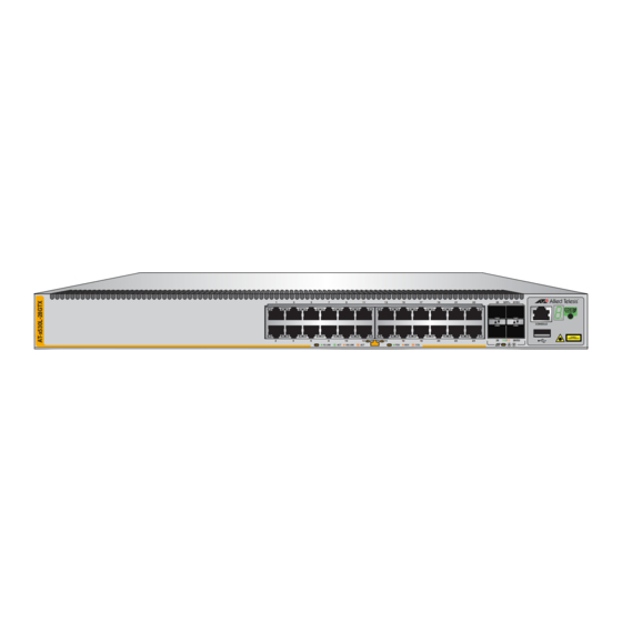
x530L-28GPX
x530L-28GTX
x530L-52GPX
x530L-52GTX
1
3
2
4
Installation Guide for Virtual Chassis
Stacking
613-002706 Rev. G
5
7
9
11
13
15
17
19
21
23
6
8
10
12
14
16
18
20
22
24
1G LINK
ACT
100 LINK
ACT
9/S1
1
7
PORTS
9-10
SFP+
CONSOLE
10G/1G
CLASS 1
LASER PRODUCT
2
8
10/S2
SFP+
5G/2.5G/1G LINK
ACT
100 LINK
ACT
PD ON
PD ERR
MAX CURRENT
1
3
5
7
9
PORTS
17-18
SFP+
10G/1G
2
4
6
8
10
5G/2.5G/1G LINK
ACT
100 LINK
ACT
PD ON
1
3
5
7
9
11
13
15
17
19
2
4
6
8
10
12
14
16
18
20
1G LINK
ACT
100 LINK
ACT
FDX
HDX
COL
25
27
29
31
33
35
37
39
41
43
26
28
30
32
34
36
38
40
42
44
FDX
HDX
COL
11
13
15
17/S1
CONSOLE
CLASS 1
18/S2
LASER PRODUCT
12
14
16
SFP+
PD ERR
MAX CURRENT
21
23
25
SFP+
27/S1
CONSOLE
CLASS 1
LASER PRODUCT
26
10G/1G
28/S2
22
24
45
47
49
SFP+
51/S1
CONSOLE
CLASS 1
LASER PRODUCT
46
48
50
10G/1G
52/S2
Advertisement
Table of Contents

Subscribe to Our Youtube Channel
Related Manuals for Allied Telesis x530L Series


Summary of Contents for Allied Telesis x530L Series
- Page 1 Series Stackable Gigabit Layer 3+ Ethernet Switches AlliedWare Plus™ v5.5.0-2 x530L-10GHXm x530L-18GHXm x530L-28GPX x530L-28GTX x530L-52GPX x530L-52GTX 9/S1 PORTS 9-10 SFP+ CONSOLE 10G/1G CLASS 1 LASER PRODUCT 10/S2 SFP+ 5G/2.5G/1G LINK 100 LINK PD ON PD ERR MAX CURRENT 17/S1...
- Page 2 Allied Telesis, Inc. has been advised of, known, or should have known, the...
- Page 3 Electrical Safety and Emissions Standards This product meets the following standards. U.S. Federal Communications Commission Radiated Energy Note: This equipment has been tested and found to comply with the limits for a Class A digital device pursuant to Part 15 of FCC Rules.
- Page 4 Translated Safety Statements Important: Safety statements that have the symbol are translated into multiple languages in the Translated Safety Statements document at www.alliedtelesis.com/library. Remarque: Les consignes de sécurité portant le symbole sont traduites dans plusieurs langues dans le document Translated Safety Statements, disponible à l'adresse www.alliedtelesis.com/ library.
-
Page 5: Table Of Contents
Contents Preface: .....................................15 Document Conventions ...............................16 Contacting Allied Telesis ..............................17 Chapter 1: Overview ................................ 19 Front and Rear Panels ................................20 Management Panel ................................23 Features ....................................24 x530L Models ................................24 Twisted Pair Ports ................................24 Power Over Ethernet ..............................25 SFP+ Transceiver Ports ...............................27 LEDs.....................................28... - Page 6 Contents Example 4..................................78 Master and Member Switches ............................79 Selection of the Master Switch ............................ 79 Switch ID Numbers ................................81 Optional Feature Licenses ..............................82 Mixed Switch Stacks ................................83 Stack Mixed-Mode Licenses............................84 Stack Mixed-Mode Commands............................ 84 Trunk Ports ..................................
- Page 7 x530 Series Installation Guide for Virtual Chassis Stacking Command Summary................................165 STACKPORT ................................165 STACK ENABLE ................................166 STACK PRIORITY ..............................166 STACK RENUMBER ..............................167 SWITCH PROVISION ..............................167 Configuring the Master x530L-10GHXm Switch......................168 General Steps for the Master x530L-10GHXm Switch ....................168 Configuring the Master x530L-10GHXm Switch – Part I ....................169 Configuring the Master x530L-10GHXm Switch –...
- Page 8 Contents...
- Page 9 Figures Figure 1: x530L-10GHXm Front Panel ..........................20 Figure 2: x530L-18GHXm Front Panel ..........................20 Figure 3: x530L-28GTX Front Panel.............................20 Figure 4: x530L-28GPX Front Panel ............................21 Figure 5: x530L-52GTX Front Panel.............................21 Figure 6: x530L-52GPX Front Panel ............................21 Figure 7: x530L-10GHXm Back Panel..........................22 Figure 8: x530L-18GHXm Back Panel..........................22 Figure 9: x530L-52GPX and x530L-28GPX Back Panel ......................22 Figure 10: x530L-52GTX and x530L-28GTX Back Panel.....................22...
- Page 10 Figures Figure 50: Bracket Holes ..............................112 Figure 51: RKMT-J14 Bracket Holes ..........................113 Figure 52: Switch Orientations with the Front Panel Facing the Front of the Equipment Rack ..........113 Figure 53: Switch Orientations with the Rear Panel Facing the Front of the Equipment Rack...........114 Figure 54: Attaching the Handles to the RKMT-J14 Brackets ....................115 Figure 55: Attaching the RKMT-J14 Brackets to the Switch ....................115 Figure 56: Installing the Switch in an Equipment Rack.......................116...
- Page 11 Tables Table 1: Basic Features ...............................22 Table 2: x530L-10GHXm Switch Twisted Pair Port Specifications ..................26 Table 3: x530L-28GTX Switch Twisted Pair Port Specifications ..................27 Table 4: x530L-28GPX Switch Twisted Pair Port Specifications ..................28 Table 5: x530L-52GTX Switch Twisted Pair Port Specifications ..................29 Table 6: x530L-52GPX Switch Twisted Pair Port Specifications ..................30 Table 7: x530L-10GHXm Twisted Pair Ports 1 - 8 LED Functions ..................32 Table 8: x530L-28GTX Twisted Pair Ports 1 - 24 LED Functions ..................34...
- Page 12 Tables...
-
Page 13: Preface
Preface This guide contains the installation instructions for the x530L Series of stackable Gigabit, Layer 3+ Ethernet switches. This preface contains the following sections: “Document Conventions” on page 14 “Contacting Allied Telesis” on page 15 Note This guide explains how to install switches as a stack with Virtual ™... -
Page 14: Document Conventions
Preface Document Conventions This document uses the following conventions: Note Notes provide additional information. Caution Cautions inform you that performing or omitting a specific action may result in equipment damage or loss of data. Warning Warnings inform you that performing or omitting a specific action may result in bodily injury. -
Page 15: Contacting Allied Telesis
guides, software release notes, white papers and data sheets for your product. Warranty - View a list of products to see if Allied Telesis warranty applies to the product you purchased and register your warranty. Allied Telesis Helpdesk - Contact a support representative. - Page 16 Preface...
- Page 17 Note This guide explains how to install switches as a stack with Virtual ™ Chassis Stacking (VCStack ). For instructions on how to install the devices as stand-alone switches, refer to the x530L Series Installation Guide for Stand-alone Switches.
-
Page 18: Chapter 1: Overview
Chapter 1: Overview Front and Rear Panels The front panels on the x530L Series switches are shown in Figure 1 through Figure 6 on page 19. 9/S1 PORTS 9-10 SFP+ CONSOLE 10G/1G CLASS 1 LASER PRODUCT 10/S2 SFP+ 5G/2.5G/1G LINK... -
Page 19: Figure 4: X530L-28Gpx Front Panel
Series Installation Guide for Virtual Chassis Stacking SFP+ 27/S1 CONSOLE CLASS 1 LASER PRODUCT 10G/1G 28/S2 1G LINK 100 LINK PD ON PD ERR MAX CURRENT POE+ Ports 1- 24 Management 10Mbps/100Mbps/1Gbps Panel Ports 1-24 1Gbps SFP/10Gbps SFP+ Transceiver Ports 25-28 Figure 4. -
Page 20: Figure 7: X530L-10Ghxm Back Panel
Chapter 1: Overview The back panels on the x530L Series switches are shown in Figure 7 through Figure 10 on page 20. AC Power Supply Connector Figure 7. x530L-10GHXm Back Panel AC Power Supply Connector Figure 8. x530L-18GHXm Back Panel... -
Page 21: Management Panel
Series Installation Guide for Virtual Chassis Stacking Management Panel Figure 11 identifies the components on the management panel. Switch ID LED Console Management eco-friendly Port Button CONSOLE Port CLASS 1 LASER PRODUCT 4567 Figure 11. Management Panel... -
Page 22: Features
Chapter 1: Overview Features The Allied Telesis x530L Series switches are stackable Gigabit, Layer 3+ Ethernet switches. The following sections list the features. x530L Models Table 1 lists the basic features for the switch models. Table 1. Basic Features x530L-... -
Page 23: Power Over Ethernet
Series Installation Guide for Virtual Chassis Stacking Half-duplex mode at 10/100Mbps Full-duplex mode at 10/100/1000Mbps Auto-MDI/MDI-X at 10/100/1000Mbps Port Link/Activity (L/A) and Duplex/Collision (D/C) LEDs The twisted pair ports on the AT-x530L-28GPX (1 to 24) switch have these... - Page 24 Chapter 1: Overview Port prioritization Mode wiring: – Classes 0-4 (Type 1 or 2 up to 30W): Mode A (MDI-x) – Classes 5-6 (Type 3 up to 45W/60W): Mode A (MDI-x) plus Mode B (MDI-x, MDI) – Classes 7-8 (Type 4 up to 75W/90W): Mode A (MDI-x) plus Mode B (MDI-x, MDI) IEEE802.3af/at compliant ...
-
Page 25: Sfp+ Transceiver Ports
Series Installation Guide for Virtual Chassis Stacking Mode wiring: – Classes 0-4 (Type 1 or 2 up to 30W): Mode A (MDI-x) – Classes 5-6 (Type 3 up to 45W/60W): Mode A (MDI-x) plus Mode B (MDI-x, MDI) –... -
Page 26: Leds
Chapter 1: Overview LEDs The port LEDs are: Link/activity LEDs for the twisted pair ports Link/activity LEDs for the SFP and SFP+ transceiver ports PoE+ LEDs for the twisted pair ports on the x530L-28GPX and x530L-52GPX switches PoE++ LEDs for the twisted pair ports on the x530L-10GHXm and ... -
Page 27: Twisted Pair Ports
Series Installation Guide for Virtual Chassis Stacking Twisted Pair Ports The specifications of the twisted pair ports are listed in Table 2 through Table 7 on page 32. Table 2. x530L-10GHXm Switch Twisted Pair Port Specifications Specification Description Port Speed Ports 1 - 8: 100Mbps or 1/2.5/5Gbps. - Page 28 Chapter 1: Overview Table 3. x530L-18GHXm Switch Twisted Pair Port Specifications Specification Description Port Speed Ports 1 - 16: 100Mbps or 1/2.5/5Gbps. 100Mbps: Set the port speed manually or with Auto-Negotiation. 1/2.5/5Gbps: The port speed is set with Auto- Negotiation only. The default is Auto-Negotiation for all ports.
- Page 29 Series Installation Guide for Virtual Chassis Stacking Table 4. x530L-28GTX Switch Twisted Pair Port Specifications Specification Description Port Speed Ports 1 - 24: 10Mbps, 100Mbps or 1 Gbps. 10Mbps/100Mbps: Set the port speed manually or with Auto-Negotiation. 1Gbps: The port speed is set with Auto- Negotiation only.
- Page 30 Chapter 1: Overview Table 5. x530L-28GPX Switch Twisted Pair Port Specifications Specification Description Port Speed Ports 1 - 24: 10Mbps, 100Mbps or 1Gbps. 10Mbps/100Mbps: Set the port speed manually or with Auto-Negotiation. 1Gbps: The port speed is set with Auto- Negotiation only.
- Page 31 Series Installation Guide for Virtual Chassis Stacking Table 6. x530L-52GTX Switch Twisted Pair Port Specifications Specification Description Port Speed Ports 1 - 48: 10Mbps, 100Mbps or 1Gbps. 10Mbps/100Mbps: Set the port speed manually or with Auto-Negotiation. 1Gbps: The port speed is set with Auto- Negotiation only.
-
Page 32: Duplex Mode
Chapter 1: Overview Table 7. x530L-52GPX Switch Twisted Pair Port Specifications Specification Description Port Speed Ports 1 - 48: 10Mbps, 100Mbps or 1Gbps. 10Mbps/100Mbps: Set the port speed manually or with Auto-Negotiation. 1Gbps: The port speed is set with Auto- Negotiation only. -
Page 33: Wiring Configuration
Series Installation Guide for Virtual Chassis Stacking Note Switch ports default to half-duplex mode when connected to 10Mbps or 100Mbps network devices that do not support Auto-Negotiation. If a network device supports full-duplex only, a duplex mode mismatch can occur, resulting in poor network performance. To prevent this,... -
Page 34: Leds
Chapter 1: Overview LEDs Each twisted pair port has two LEDs that display the port status. x530L-10GHXm The LEDs indicate Link/Activity (L/A) and PoE (PD ON/PD ERR/MAX CURRENT) information. These LEDs are shown in Figure 12. L/A LED PoE LED Figure 12. -
Page 35: Figure 13: X530L-18Ghxm Twisted Pair Ports
Series Installation Guide for Virtual Chassis Stacking Table 8. x530L-10GHXm Twisted Pair Ports 1 - 8 LED Functions (Continued) Ports State Description Solid Green PD On - The switch is delivering power to a powered device connected to the port. - Page 36 Chapter 1: Overview The states of the x530L-18GHXm LEDs are described in Table 9. Table 9. x530L-18GHXm Twisted Pair Ports 1 - 16 LED Functions Ports State Description Solid Green The port has established a 1/2.5/5Gbps link to a network device. Flashing The port is transmitting or receiving data at 1/2.5/ Green...
-
Page 37: Figure 14: X530L-28Gtx Twisted Pair Port Leds
Series Installation Guide for Virtual Chassis Stacking x530L-28GTX The LEDs indicate Link/Activity (L/A) and Duplex/Collision (FDX/HDX/ COL) information. These LEDs are shown in Figure 14. L/A LED D/C LED Figure 14. x530L-28GTX Twisted Pair Port LEDs The states of the x530L-28GTX LEDs are described in Table 10. -
Page 38: Figure 15: X530L-52Gtx Twisted Pair Port Leds
Chapter 1: Overview x530L-52GTX The LEDs indicate Link/Activity (L/A) and Duplex/Collision (FDX/HDX/ COL) information. These LEDs are shown in Figure 15. L/A LED D/C LED Figure 15. x530L-52GTX Twisted Pair Port LEDs The states of the x530L-52GTX LEDs are described in Table 11. Table 11. -
Page 39: Figure 16: X530L-28Gpx Twisted Pair Ports
Series Installation Guide for Virtual Chassis Stacking x530L-28GPX The LEDs indicate Link/Activity (L/A) and PoE (PD ON/PD ERR/MAX CURRENT) information. These LEDs are shown in Figure 16. L/A LED PoE LED Figure 16. x530L-28GPX Twisted Pair Ports The states of the x530L-28GTX LEDs are described in Table 12. -
Page 40: Figure 17: X530L-52Gpx Twisted Pair Ports
Chapter 1: Overview Table 12. x530L-28GPX Twisted Pair Ports 1 - 24 LED Functions (Continued) Ports State Description Solid Green PD On - The switch is delivering power to a powered device connected to the port. Solid Amber PD Error - The switch has shut down PoE on the port because of a fault condition. - Page 41 Series Installation Guide for Virtual Chassis Stacking Table 13. x530L-52GPX Twisted Pair Ports 1 - 48 LED Functions Ports State Description Solid Green The port has established a 1Gbps link to a network device. Flashing The port is transmitting or receiving data at 1Gbps.
-
Page 42: Power Over Ethernet
Chapter 1: Overview Power Over Ethernet The x530L-10GHXm, x530L-18GHXm, x530L-28GPX, and x530L-52GPX switches feature PoE on twisted pair ports. With PoE, the switch supplies DC power to network devices over the same twisted pair cables that carry the network traffic. PoE can make it easier to install networks. -
Page 43: Powered Device Classes
Series Installation Guide for Virtual Chassis Stacking Powered Device Powered devices are grouped into the nine classes listed in Table 14. The classes are based on the amount of power the devices require. The Classes x530L-28GPX and x530L-52GPX switches support classes 0 to 4. The x530L-10GHXm and x530L-18GHXm switches support classes 0 to 8. -
Page 44: Port Prioritization
Chapter 1: Overview conditions, the switch can support up to eight Class 6 powered devices with the maximum 51.3.5W or up to five Class 8 powered devices with the maximum of 71.3W. The x530L-18GHXm switch has one power supply. It can supply 720W of PoE power. -
Page 45: Wiring Implementation
Series Installation Guide for Virtual Chassis Stacking The lowest priority level is Low. This is the default setting. Ports set to this level only receive power if all of the ports assigned to the other two levels are already receiving power. As with the other levels, if there is not enough power to support all of the ports set to the Low priority level, power is provided to the ports based on port number, in ascending order. -
Page 46: Sfp+ Transceiver Ports
Note SFP or SFP+ transceivers must be purchased separately. For a list of supported transceivers, refer to the product data sheet on the Allied Telesis web site. LEDs Each transceiver port has one LED. The LEDs are located between the ports. - Page 47 Series Installation Guide for Virtual Chassis Stacking The LEDs display link status and activity. The possible LED states are described in Table 15. Table 15. Link and Activity Status LEDs for the 1Gbps and 10Gbps Ports State Description Solid Green The transceiver has established a 10Gbps link to a network device.
-
Page 48: Eco-Friendly Button
Chapter 1: Overview eco-friendly Button The eco-friendly button on the front panel of the switch is used to toggle the port LEDs on or off. You can turn off the LEDs to conserve electricity when you are not monitoring the device. You can also toggle the LEDs with the ECOFRIENDLY LED and NO ECOFRIENDLY LED commands in the Global Configuration mode of the command line interface of the AlliedWare Plus management software. -
Page 49: Vcstack Feature
Note This guide explains how to install switches as a stack with Virtual ™ Chassis Stacking (VCStack ). For instructions on how to install the devices as stand-alone switches, refer to the x530L Series Installation Guide for Stand-alone Switches. -
Page 50: Switch Id Led
Chapter 1: Overview Switch ID LED The switch ID LED, shown in Figure 19, displays the ID number of the switch. A stand-alone switch has the ID number 0. Switches in a VCStack have the numbers 1 to 8. Chapter 7, “Building the Trunk with the Default 10Gbps Stacking Ports”... -
Page 51: Figure 20: Switch Id Led Description
Series Installation Guide for Virtual Chassis Stacking The states of the LED when the switch is not operating in the low power mode are shown in Figure 20. The switch is booting up. The switch has encountered a fault condition. -
Page 52: Usb Port
Chapter 1: Overview USB Port The USB port on the management panel is used for the following functions: Store configuration files on flash drives. Restore configuration files to switches that have lost or corrupted settings. Configure replacement units by downloading configuration files ... -
Page 53: Console Port
Series Installation Guide for Virtual Chassis Stacking Console Port The Console port is an RS232 serial management port. You use the port to access the AlliedWare Plus management software on the switch to configure the feature settings or monitor status or statistics. This type of... -
Page 54: Power Supply
Chapter 1: Overview Power Supply Pre-Installed AC The x530L Series switches come with one or two pre-installed AC power supplies depending on the model: Power Supply Two power supplies: x530L-28GPX, x530L-28GTX, x530L-52GTX and x530L-52GPX One power supply: x530L-10GHXm and x530L-18GHXm ... -
Page 55: Software And Hardware Releases
Series Installation Guide for Virtual Chassis Stacking Software and Hardware Releases Software and hardware releases for the AlliedWare Plus operating software and x530L Series switches are listed in Table 16. Table 16. Software and Hardware Releases Software Hardware VCStack Version v5.4.8-2... - Page 56 Chapter 1: Overview...
- Page 57 Chapter 2 Virtual Chassis Stacking The following sections are discussed in this chapter: “Overview” on page 58 “Stacking Guidelines” on page 59 “Stack Trunks” on page 61 “Stack Trunks of 10Gbps Ports” on page 62 “Stack Trunks of 5Gbps Ports on the x530L-10GHXm or x530L- ...
-
Page 58: Chapter 2: Virtual Chassis Stacking
Chapter 2: Virtual Chassis Stacking Overview The VCStack feature is used to connect multiple x530L Series switches into a single, virtual networking unit. Some of the benefits of the VCStack feature are listed here: Simplifies management - You can manage the devices of the stack ... -
Page 59: Stacking Guidelines
No additional software or licenses are required for stacking within the x530L Series switches. A stack can also have x530, x530DP and x530L Series switches. However, this type of stack, referred to as a mixed stack, requires a license and additional configuration commands. Refer to “Mixed Switch Stacks”... - Page 60 Chapter 2: Virtual Chassis Stacking When using a multi-speed port as a stack port, it supports 1 to 8 links.
-
Page 61: Stack Trunks
Series Installation Guide for Virtual Chassis Stacking Stack Trunks Stack trunks connect the switches of a stack together. A stack trunk consists of a minimum of two ports on each device. For switches with AlliedWare Plus v5.4.9 or later, you can choose the two ports of the trunk. -
Page 62: Stack Trunks Of 10Gbps Ports
SFP+ transceivers and direct attach cables used for a stack trunk must be from Allied Telesis. Switches will not form a stack with transceivers from other network equipment providers. For a list of supported transceivers, refer to the product data sheet on the Allied Telesis web site. -
Page 63: Figure 21: Valid Stack Trunk Using Default Stacking Ports 9 To 10 On 10-Port X530L Switches
Series Installation Guide for Virtual Chassis Stacking Figure 21 shows examples of stack trunks for two, three, and four switches, using the default stacking ports 9 and 10 on 10-port x530L- 10GHXm switches. Stack of Two Switches Stack of Three Switches Stack of Four Switches Figure 21. -
Page 64: Figure 22: Valid Stack Trunk Using Default Stacking Ports 17 To 18 On 18-Port X530L Switches
Chapter 2: Virtual Chassis Stacking Figure 22 shows examples of stack trunks for two, three, and four switches, using the default stacking ports 17 and 18 on 18-port x530L- 18GHXm switches. 27/S1 27/S1 CONSOLE CLASS 1 LASER PRODUCT 28/S2 28/S2 Stack of Two Switches 27/S1 27/S1... -
Page 65: Figure 23: Valid Stack Trunk Using Default Stacking Ports 27 To 28 On 28-Port X530L Switches
Series Installation Guide for Virtual Chassis Stacking Figure 23 shows examples of stack trunks for two, three, and four switches, using the default stacking ports 27 and 28 on 28-port x530L- 28GPX and x530L-28GTX switches. 27/S1 SFP+ 27/S1 CONSOLE... -
Page 66: Figure 24: Valid Stack Trunk Using Default Stacking Ports 51 To 52 On 52-Port X530L Switches
Chapter 2: Virtual Chassis Stacking Figure 24 shows examples of stack trunks for two, three, and four switches, using the default stacking ports 51 and 52 on 52-port x530L- 52GPX and x530L-52GTX switches. Stack of Two Switches Stack of Three Switches Stack of Four Switches Figure 24. - Page 67 Series Installation Guide for Virtual Chassis Stacking In stacks of three or more 28- or 52-port switches the amount of inter- switch network traffic might require a stacking trunk with greater bandwidth than that provided by the default ports of: x530L-28GPX and x530L-28GTX ports 27 and 28.
- Page 68 Chapter 2: Virtual Chassis Stacking Figure 25 shows examples of stacks of three and four switches using all four SFP+ ports for the stack trunk. SFP+ 27/S1 CONSOLE CLASS 1 LASER PRODUCT 10G/1G 28/S2 5G/2.5G/1G LINK PORTS 1-20 1G LINK 100 LINK PD ON PD ERR...
- Page 69 Series Installation Guide for Virtual Chassis Stacking Figure 26 shows an example of a stack of four switches using all four SFP+ ports for the stack trunk with a combination of 28- and 52-port switches. SFP+ 27/S1 CONSOLE CLASS 1...
- Page 70 Chapter 2: Virtual Chassis Stacking 10Gbps stack trunks can have a combination of fiber optic transceivers and SP10TW direct attach cables. Figure 27 shows an example of a 10Gbps stack trunk with both fiber optic and SP10TW direct connect cables. 27/S1 27/S1 SFP+...
-
Page 71: Stack Trunks Of 5Gbps Ports On The X530L-10Ghxm Or X530L-18Ghxm Switch
Series Installation Guide for Virtual Chassis Stacking Stack Trunks of 5Gbps Ports on the x530L-10GHXm or x530L- 18GHXm Switch The 10Gbps SFP+ ports on the x530L-10GHXm or x530L-18GHXm switch are not the only ports you can use for a trunk of a stack. If you prefer to use the 10Gbps ports for other functions, you can use the 5Gbps ports for the trunk instead. - Page 72 Chapter 2: Virtual Chassis Stacking A trunk of 5Gbps ports for a stack of two switches can have two or more links per switch. As mentioned previously, the more links in a trunk, the greater its bandwidth and resiliency. Examples are shown in Figure 28. Figure 28.
- Page 73 Series Installation Guide for Virtual Chassis Stacking A trunk of 5Gbps ports for a stack of three or more x530L-10GHXm switches can have from two to all 5Gbps ports per switch. Refer to Figure 29. Figure 29. Trunks of 5Gbps Ports for Stacks of Three x530L-10GHXm...
-
Page 74: Invalid Stack Trunks
Chapter 2: Virtual Chassis Stacking Invalid Stack Trunks Figure 30 through Figure 33 on page 75 show examples of different types of invalid stack trunks. Example 1 Stack trunks must be direct links between trunk ports. There cannot be any intermediary networking devices, such as media converters, Ethernet switches, or routers, between trunk ports. -
Page 75: Example 3
Series Installation Guide for Virtual Chassis Stacking Example 3 Trunks must have the same number of physical links between switches. Figure 32 is invalid because the top and middle switches are connected with two links while the top and middle switches are connected to the bottom switch with only one link each. -
Page 76: Master And Member Switches
assigns new ID numbers to resolve situations where two or more switches have the same ID number. Verify that the stacking transceivers are from Allied Telesis and they are cabled correctly. The parameter settings of the switches of the stack are stored in configuration files in the flash memories of the master and member switches. - Page 77 Series Installation Guide for Virtual Chassis Stacking When switches have the same priority values, they compare their MAC addresses to select the master switch. As with the priority value, the lower the MAC address, the higher the priority. The switch with the lowest MAC address becomes the master switch.
-
Page 78: Switch Id Numbers
Chapter 2: Virtual Chassis Stacking Switch ID Numbers Each switch in a stack must have a unique ID number. The possible ID numbers depend on the version number of the AlliedWare Plus management software. The ID numbers 1 to 8 for up to eight switches in a stack with AlliedWare Plus v5.4.9-2 or later. -
Page 79: Optional Feature Licenses
Unlocking optional features requires licenses from Allied Telesis. For a list of optional feature licenses for the product, refer to its product sheet on the Allied Telesis web site. Here are the guidelines to feature licenses for a stack of x530L Series switches: The VCStack feature is part of the base features of the switch. -
Page 80: Mixed Switch Stacks
x530DP If you have previously worked with other Allied Telesis products that support stacking, than you may already know that the feature is typically not supported across switches from different series. This means that all the switches of a stack usually have to be from the same series. -
Page 81: Stack Mixed-Mode Licenses
Mode Licenses from Allied Telesis and install the licenses on the switches. Switches of mixed stacks need the licenses to form the stacks. The different switch series have different stack mixed-mode licenses. To receive the correct type and number of licenses, be sure to specify the number of x530L, x530, and x530DP switches when ordering the licenses. - Page 82 Chapter 2: Virtual Chassis Stacking For a mixed stack of 28- or 52-port switches, the trunk ports have to be SFP+ ports. The switches should have AlliedWare Plus v5.4.9 or later. You have to install stack mixed-mode licenses on all the switches. ...
-
Page 83: Planning The Stack
Series Installation Guide for Virtual Chassis Stacking Planning the Stack Here are factors to consider when planning a stack: Have you selected the stack ports for the trunk? The default stack ports are 10Gbps ports. Refer to “Stack Trunks” on page 61. -
Page 84: Configuring Mixed-Mode Vcstacking
Chapter 2: Virtual Chassis Stacking Configuring Mixed-Mode VCStacking To configure mixed-mode VCStacking, on each unit in the stack you must: 1. Install the mixed-mode stacking license. Once you have downloaded your license, you can transfer it onto the device’s Flash storage by any preferred method. -
Page 85: Stacking Worksheet
Series Installation Guide for Virtual Chassis Stacking Stacking Worksheet Configuring and maintaining a stack may be easier if you use the worksheet in Table 18. Table 18. Stacking Worksheet Switch Model/ Switch Priority Version Trunk Ports Location Number Master... - Page 86 ID LEDs on the front panels and you use the numbers to configure the individual ports. Allied Telesis recommends assigning the ID 1, the default value, to the master switch. You should decide ahead of time, before beginning the configuration procedures, the ID assignments of the switches.
- Page 87 Series Installation Guide for Virtual Chassis Stacking Table 19. Stacking Worksheet Columns (Continued) Column Description AW+ Version This column is for writing down the version Number numbers of the AlliedWare Plus management software on the switches. The switches might not be able to form the stack if they have different versions.
- Page 88 Chapter 2: Virtual Chassis Stacking...
- Page 89 Chapter 3 Beginning the Installation This chapter contains the following sections: “Reviewing Safety Precautions” on page 90 “Choosing a Site for the Switch” on page 95 “Unpacking the x530L-10GHXm Switch” on page 96 “Unpacking the x530L-18GHXm Switch” on page 99 ...
-
Page 90: Chapter 3: Beginning The Installation
Chapter 3: Beginning the Installation Reviewing Safety Precautions Please review the following safety precautions before beginning the installation procedure. Important: Safety statements that have the symbol are translated into multiple languages in the Translated Safety Statements document at https://www.alliedtelesis.com/en/documents/translated-safety- statements. - Page 91 Series Installation Guide for Virtual Chassis Stacking Warning To prevent electric shock, do not remove the cover. No user- serviceable parts inside. This unit contains hazardous voltages and should only be opened by a trained and qualified technician. To avoid the possibility of electric shock, disconnect electric power to the product before connecting or disconnecting the LAN cables.
- Page 92 E25 Warning The chassis may be heavy and awkward to lift. Allied Telesis recommends that you get assistance when mounting the chassis in an equipment rack. E28 Note Use dedicated power circuits or power conditioners to supply reliable electrical power to the device.
- Page 93 Series Installation Guide for Virtual Chassis Stacking Warning This unit might have more than one power cord. To reduce the risk of electric shock, disconnect all power cords before servicing the unit. E30 Note If installed in a closed or multi-unit rack assembly, the operating ambient temperature of the rack environment may be greater than the room ambient temperature.
- Page 94 Chapter 3: Beginning the Installation Warning This equipment must be installed in a Restricted Access location. E45 Caution The unit does not contain serviceable components. Please return damaged units for servicing. E42 Warning The temperature of an operational SFP or SFP+ transceiver may exceed 70°...
-
Page 95: Choosing A Site For The Switch
Series Installation Guide for Virtual Chassis Stacking Choosing a Site for the Switch Observe these requirements when planning the installation of the switch. Before installing the switch in an equipment rack, check that the rack is safely secured so that it will not tip over. Devices in a rack should be installed starting at the bottom, with the heavier devices near the bottom of the rack. -
Page 96: Unpacking The X530L-10Ghxm Switch
The items in the box are listed here: A - Protective bag B - x530L-10GHXm Switch C - Accessory kit Note You should retain the original packaging material in case you need to return the unit to Allied Telesis. - Page 97 Series Installation Guide for Virtual Chassis Stacking Figure 35 here and Figure 36 on page 98 list the items in the accessory kit. Contact your Allied Telesis sales representative for assistance if any item is missing or damaged. One 2m (6.6 ft) local management cable with RJ-45 (8P8C) and DB-9 (D- sub 9-pin) connectors.
- Page 98 Chapter 3: Beginning the Installation Two RKMT-J14 equipment rack brackets Two handles for the RKMT-J14 equipment rack brackets Four screws for attaching the handles to the RKMT-J14 equipment rack brackets: Length: 6.0mm (0.2 in.) Diameter: 3.0mm (0.1 in.) Four rubber bumper feet Figure 36.
-
Page 99: Unpacking The X530L-18Ghxm Switch
Series Installation Guide for Virtual Chassis Stacking Unpacking the x530L-18GHXm Switch Figure 37 shows the shipping box for the x530L-18GHXm Switch. BACK ENDCAP DOCUMENTS SWITCH PROTECTIVE BAG ACCESSORY KIT 4600 Figure 37. x530L-18GHXm Switch Shipping Box The items in the box are listed here: Protective bag ... - Page 100 Chapter 3: Beginning the Installation Figure 38 lists the items in the accessory kit. Contact your Allied Telesis sales representative for assistance if any item is missing or damaged. One 2m (6.6 ft) local management cable with RJ-45 (8P8C) and DB-9 (D- sub 9-pin) connectors.
- Page 101 Series Installation Guide for Virtual Chassis Stacking Unpacking the x530L-28GTX x530L-28GPX x530L-52GTX, or x530L- 52GPX Switch Figure 39 shows the items provided in the shipping box for the switch. BACK ENDCAP DOCUMENTS SWITCH PROTECTIVE BAG ACCESSORY KIT 4600 Figure 39. 28- or 52-Port Switch Shipping Box...
- Page 102 Figure 40 lists the items that are included in the x530L-28GTX, x530L- 28GPX, x530L-52GTX, or x530L-52GPX Switch accessory kit. Contact your Allied Telesis sales representative for assistance if any item is missing or damaged. 1 local management cable 2m (6.6 ft) with RJ-45 (8P8C) and DB-9 (D-sub 9-pin) connectors.
-
Page 103: Chapter 4: Installing The Switch On A Table
Chapter 4 Installing the Switch on a Table This chapter contains the instructions for installing the switch on a table or desktop. Warning Switches should not be stacked on a table or desktop. They could present a physical safety hazard if you need to move or replace switches. -
Page 104: Installing The Bumper Feet
Chapter 4: Installing the Switch on a Table Installing the Bumper Feet The switch comes with four bumper feet in the accessory kit. The feet, which are reusable, are used when installing the switch on a table. If they are already assembled, disassemble them by removing the rivets and rivet housings from the bumper feet. - Page 105 Series Installation Guide for Virtual Chassis Stacking Note The following procedure assumes that you have already reviewed the information and performed the procedures in Chapter 3, “Beginning the Installation” on page 89. To install the switch on a table, perform the following procedure: 1.
- Page 106 Chapter 4: Installing the Switch on a Table Figure 45. Inserting the Rivet into the Bumper Foot 5. Repeat steps 2 to 4 to install the remaining bumper feet. 6. Turn the switch over and place it on a flat, secure desk or table, leaving ample space around it for ventilation.
-
Page 107: Figure 48: Rkmt-J15 Bracket
Chapter 5 Installing the Switch in an Equipment Rack This chapter provides instructions for installing the switch in an equipment rack, and contains the following sections: “Overview of Installing the x530L-10GHXm Switch in an Equipment Rack” on page 108 “Installing the x530L-10GHXm Switch in an Equipment Rack with the ... -
Page 108: Chapter 5: Installing The Switch In An Equipment Rack
Chapter 5: Installing the Switch in an Equipment Rack Overview of Installing the x530L-10GHXm Switch in an Equipment Rack You can install the x530L-10GHXm switch in a 19-inch equipment rack two ways. One way is with the RKMT-J14 brackets that come with the switch. - Page 109 Series Installation Guide for Virtual Chassis Stacking The bracket lets you install two switches side-by-side. Refer to Figure 48. Figure 48. RKMT-J15 Bracket with Switches Note The RKMT-J15 Bracket is purchased separately. For installation instructions, refer to “Installing the x530L-10GHXm Switch...
-
Page 110: Installing The X530L-10Ghxm Switch In An Equipment Rack With The Rkmt-J14 Brackets
Chapter 5: Installing the Switch in an Equipment Rack Installing the x530L-10GHXm Switch in an Equipment Rack with the RKMT-J14 Brackets This section contains the procedure for installing the x530L-10GHXm Switch in a standard 19-inch equipment rack, with the RKMT-J14 Brackets included with the switch. - Page 111 Series Installation Guide for Virtual Chassis Stacking Set 1 Set 2 Figure 50. RKMT-J14 Bracket Holes You can use the different sets of holes on the switch and brackets to install the switch in the equipment rack in a variety of orientations. You can install it with the front panel flush with, extending in front of, or recessed behind the front of the equipment rack.
-
Page 112: Installing The Switch
Please review the installation guidelines in “Choosing a Site for the Switch” on page 52 before installing the switch in an equipment rack. Caution The chassis may be heavy and awkward to lift. Allied Telesis recommends that you get assistance when mounting the chassis in an equipment rack. E28... - Page 113 Series Installation Guide for Virtual Chassis Stacking Figure 53. Attaching the Handles to the RKMT-J14 Brackets 2. Place the switch on a level, secure surface. 3. Attach the two brackets to the sides of the switch in the selected position, using the eight M4x6mm screws included with the unit.
- Page 114 Chapter 5: Installing the Switch in an Equipment Rack 4. Have another person hold the switch at the desired location in the equipment rack while you secure it using four standard equipment rack screws (not provided). Refer to Figure 55. Figure 55.
-
Page 115: Installing The X530L-10Ghxm Switch In An Equipment Rack With The Rkmt-J15 Bracket
Series Installation Guide for Virtual Chassis Stacking Installing the x530L-10GHXm Switch in an Equipment Rack with the RKMT-J15 Bracket This section contains the procedure for installing the x530L-10GHXm switch in a standard 19-inch equipment rack, with the optional RKMT-J15 Bracket. - Page 116 Chapter 5: Installing the Switch in an Equipment Rack Figure 56. Installing the RKMT-J15 Bracket in the Equipment Rack 2. Loosen the two thumbscrews on the front of the bracket. Refer to Figure 57. Figure 57. Loosening the Two Thumbscrews on the Front of the RKMT- J15 Bracket...
- Page 117 Series Installation Guide for Virtual Chassis Stacking 3. Slide out the bracket tray. Refer to Figure 58. Figure 58. Sliding Out the Bracket of the RKMT-J15 Note Follow steps 4 to 6 to remove the plastic feet from the bottom of the switch.
- Page 118 Chapter 5: Installing the Switch in an Equipment Rack 6. Turn the switch over so that it is right-side up. 7. Place the switch on one side of the bracket. Align the front panel with the front edge of the bracket. If you are installing only one switch, you may install it on either the left or right side.
- Page 119 Series Installation Guide for Virtual Chassis Stacking 10. Slide in the bracket tray. Refer to Figure 62. Figure 62. Sliding in the Bracket 11. Tighten the two thumbscrews to secure the bracket to the rack. Refer to Figure 63.
- Page 120 Chapter 5: Installing the Switch in an Equipment Rack 12. After installing all the switches of the stack, do one of the following: To build the stack with the default stacking ports, refer to Chapter 7, “Building the Trunk with the Default 10Gbps Stacking Ports” on page 141.
-
Page 121: Required Items
Series Installation Guide for Virtual Chassis Stacking Installing the x530L-18GHXm, x530L-28GTX x530L-28GPX, x530L- 52GTX, or x530L-52GPX Switch in an Equipment Rack This section contains the procedure for installing the x530L-18GHXm, x530L-28GTX, x530L-28GPX, x530L-52GTX, or x530L-52GPX Switch in a standard 19-inch equipment rack using the brackets supplied with the unit. -
Page 122: Installing The Switch
Please review the installation guidelines in “Choosing a Site for the Switch” on page 95 before installing the switch in an equipment rack. Caution The chassis can be heavy and awkward to lift. Allied Telesis recommends that you get assistance when mounting the chassis in an equipment rack. E28... - Page 123 Series Installation Guide for Virtual Chassis Stacking To install the switch in a 19-inch equipment rack, perform the following procedure: 1. Place the switch on a level, secure surface. 2. Attach the two brackets to the sides of the switch in the selected position, using the eight M4x6mm screws supplied with the unit.
- Page 124 Chapter 5: Installing the Switch in an Equipment Rack 3. Have another person hold the switch at the desired location in the equipment rack while you secure it using four standard equipment rack screws (not provided). Refer to Figure 67. S FP U LT N SO...
- Page 125 Chapter 6 Installing the Switch on a Wall The procedures in this chapter are listed here: “Switch Orientations on a Wall” on page 126 “Installation Guidelines” on page 127 “Plywood Base for a Wall with Wooden Studs” on page 131 ...
-
Page 126: Chapter 6: Installing The Switch On A Wall
Chapter 6: Installing the Switch on a Wall Switch Orientations on a Wall Install the switch on a wall with the front panel facing up, left or right as shown in Figure 68. Do not install the switch with the front panel facing down. -
Page 127: Installation Guidelines
Series Installation Guide for Virtual Chassis Stacking Installation Guidelines Here are the guidelines for installing the switch on a wall: You can install the switches on a wall with the front panels facing up, left, or right. Do not install the switches with the front panels facing down. - Page 128 Chapter 6: Installing the Switch on a Wall Stud finder for a wooden wall, capable of identifying the middle of wall studs and hot electrical wiring (not provided) Drill and 1/4” carbide drill bit for a concrete wall (not provided) ...
- Page 129 Series Installation Guide for Virtual Chassis Stacking Figure 70. Attaching Wall Brackets to x530L-28GTX, x530L-28GPX, x530L-52GTX, and x530L-52GPX Switches Note If the wall material requires pre-drilled holes, perform steps 5 to 9. Otherwise, go to step 10. 5. Have another person hold the switch on the concrete wall at the selected location for the device while you use a pencil or pen to mark the wall with the locations of the screw holes in the brackets.
- Page 130 Chapter 6: Installing the Switch on a Wall Figure 71. Marking the Screw Holes 6. Place the switch on a table or desk. 7. Use the stud finder to check for hot electrical wires at the locations of the screw holes. Warning Do not install the switch on a wall near hot electrical wires.
-
Page 131: Plywood Base For A Wall With Wooden Studs
Series Installation Guide for Virtual Chassis Stacking Plywood Base for a Wall with Wooden Studs If you are installing the switch on a wall that has wooden studs, use plywood base for the device. (A plywood base is not required for a concrete wall.) Refer to Figure 72. -
Page 132: Installing A Plywood Base
Chapter 6: Installing the Switch on a Wall Installing a Plywood Base A plywood base is recommended when installing the switch on a wall that has wooden studs. Refer to Figure 73. Consult a qualified building contractor for installation instructions for the plywood base. The installation guidelines are listed here: Use a stud finder to identify the middle of studs and hot electrical ... -
Page 133: Installing The Switch On A Plywood Base
After the plywood base for the switch has been installed on the wall, install the switch. See “Reviewing Safety Precautions” on page 90 and “Choosing a Site for the Switch” on page 95 before performing this procedure. Allied Telesis recommends a minimum of two people for this procedure. Warning The device is heavy. - Page 134 Chapter 6: Installing the Switch on a Wall Brackets positions to install the switch with the front panel on the left. 456 8 S 1-2 S 21- /2.5 G LIN 27 /S /2. 5G 28 /S Brackets positions to install the switch with the front panel on the right.
- Page 135 Series Installation Guide for Virtual Chassis Stacking 3. After attaching the brackets, have another person hold the switch on the plywood base on the wall while you secure it with the M4x32.3mm screws included with the switch. Refer to Figure 76 for the x530L- 28GPX, x530L-28GTX, x530L-52GPX, or x530L-52GTX switch or Figure 77 on page 136 for the x530L-10GHXm switch.
- Page 136 Chapter 6: Installing the Switch on a Wall Figure 77. Securing the x530L-10GHXm Switch to the Plywood Base 4. After installing all the switches of the stack, do one of the following: To build the stack with the default stacking ports, go to Chapter 7, ...
-
Page 137: Installing The Switch On A Concrete Wall
Series Installation Guide for Virtual Chassis Stacking Installing the Switch on a Concrete Wall This section contains the instructions for installing the switch on a concrete wall. Please review the information in the following sections before performing the procedure: “Switch Orientations on a Wall”... - Page 138 Chapter 6: Installing the Switch on a Wall 4596 Figure 78. Marking the Locations of the Bracket Holes on a Concrete Wall 4. Place the switch on a table. 5. Use a drill and a 1/4-inch carbide drill bit to pre-drill the holes you marked in step 3.
- Page 139 Series Installation Guide for Virtual Chassis Stacking 7. Have another person hold the switch at the selected wall location while you secure it to the wall with the M4x32mm screws provided. Refer to Figure 79. 4597 Figure 79. Installing the Switch on a Concrete Wall 8.
- Page 140 Chapter 6: Installing the Switch on a Wall...
- Page 141 Chapter 7 Building the Trunk with the Default 10Gbps Stacking Ports This chapter contains the following procedures: “Introduction” on page 142 “Installing the Power Cord Retaining Clip(s)” on page 143 “Powering On the Switches Individually” on page 144 ...
-
Page 142: Chapter 7: Building The Trunk With The Default 10Gbps Stacking Ports
Chapter 7: Building the Trunk with the Default 10Gbps Stacking Ports Introduction This chapter contains instructions for building the stack using the default 10Gbps stacking ports. The procedure does not require any configuration steps because the stacking feature is enabled by default. The default stacking ports are: Ports 9 and 10 on the x530L-10GHXm ... -
Page 143: Installing The Power Cord Retaining Clip(S)
Series Installation Guide for Virtual Chassis Stacking Installing the Power Cord Retaining Clip(s) The power cord retaining clips that come with the switch protect the power cords from being accidentally unplugged from the unit. 1. To install a power cord retaining clip, position it the “u” part facing down, press in the sides, and insert the ends of the clip into the holes in the retaining bracket on the AC connector on the switch. -
Page 144: Powering On The Switches Individually
Chapter 7: Building the Trunk with the Default 10Gbps Stacking Ports Powering On the Switches Individually This procedure explains how you can control the assignment of the ID numbers of the switches by powering on the units one at a time during the initial power-on sequence. - Page 145 Series Installation Guide for Virtual Chassis Stacking 2. Power on the switch you want to be assigned ID number 1 by connecting its power cord to the AC connector on the back panel. Refer to Figure 82 on page 145.
- Page 146 Chapter 7: Building the Trunk with the Default 10Gbps Stacking Ports 4. Connect the power cord to an appropriate power source. See Figure 83. Refer to “Power Specifications” on page 221 for the power specifications of the switches. Figure 83. Plugging in the AC Power Cord to an AC Source Warning Power cord is used as a disconnection device.
- Page 147 Series Installation Guide for Virtual Chassis Stacking 8. If there is a third switch, power it on and wait another two minutes for it to join the stack as a member with the ID number 3. 9. If there are additional switches, continue to power each one at a time and wait two minutes for it to join the stack as a member with the next ID number.
-
Page 148: Powering On The Switches Simultaneously
Chapter 7: Building the Trunk with the Default 10Gbps Stacking Ports Powering On the Switches Simultaneously If you want the switches of the stack to use their MAC addresses to automatically assign the ID numbers during the initial power on sequence, all you have to do is power them on simultaneously, rather than one at a time as in the previous procedure. - Page 149 Series Installation Guide for Virtual Chassis Stacking Warning Power cord is used as a disconnection device. To de-energize equipment, disconnect the power cord. E3 Note Pluggable Equipment. The socket outlet shall be installed near the equipment and shall be easily accessible. E5 2.
-
Page 150: Starting A Local Management Session
VT100 terminal or a VT100 terminal emulator. Performing a local management session on the switch requires a management cable. Allied Telesis offers two cables. One cable comes with the switch. It has an RJ-45 (8P8C) connector that connects to the Console port on the switch and a DB-9 (D-sub 9-pin) connector that connects to your workstation. - Page 151 Series Installation Guide for Virtual Chassis Stacking Figure 86. Management Workstation, VT-Kit3 Management Cable, and Switch To start a local management session on the stack, perform the following procedure: 1. Connect the RJ-45 connector of the management cable to the console port on the front panel of any switch in the stack.
- Page 152 Chapter 7: Building the Trunk with the Default 10Gbps Stacking Ports 3. Configure the terminal or terminal emulator program as follows: Default baud rate: 9,600 bps (range is 9,600 to 115,200 bps) Data bits: 8 Parity: None Stop bits: 1 ...
-
Page 153: Verifying The Stack
Series Installation Guide for Virtual Chassis Stacking Verifying the Stack To verify the stack, perform the following procedure: 1. Start a local management session on any switch in the stack. Refer to “Starting a Local Management Session” on page 150. -
Page 154: Adding Ports 25 And 26 On The X530L-28Gpx Or X530L-28Gtx Switch To The Stack Trunk
Chapter 7: Building the Trunk with the Default 10Gbps Stacking Ports Adding Ports 25 and 26 on the x530L-28GPX or x530L-28GTX Switch to the Stack Trunk This procedure explains how to add ports 25 and 26 to the stack trunk on the x530L-28GPX or x530L-28GTX switch. - Page 155 Series Installation Guide for Virtual Chassis Stacking Table 20. Adding Ports 25 and 26 to the Stack Trunk on the x530L-28GPX or x530L-28GTX Switch Step Description and Command Enter the WRITE command to save your change. awplus# write Building configuration ...
-
Page 156: Adding Ports 49 And 50 On The X530L-52Gpx Or X530L-52Gtx Switch To The Stack Trunk
Chapter 7: Building the Trunk with the Default 10Gbps Stacking Ports Adding Ports 49 and 50 on the x530L-52GPX or x530L-52GTX Switch to the Stack Trunk This procedure explains how to add ports 49 and 50 to the stack trunk on the x530L-52GPX or x530L-52GTX switches. - Page 157 Series Installation Guide for Virtual Chassis Stacking Table 21. Adding Ports 49 and 50 to the Stack Trunk on the x530L-52GPX or x530L-52GTX Switch Step Description and Command Enter the WRITE command to save your change. awplus# write Building configuration ...
-
Page 158: Monitoring The Initialization Processes
/ /______\ \ \_ __/ /| ______ | | ______ | \ ____ / /______/\____\ \/ /____________/ Allied Telesis Inc. AlliedWare Plus (TM) v5.5.0 Current release filename: x530L-5.5.0-2-rcl.rel... Built: Mon Nov 26 01:57:50 UTC 2021 Mounting static filesystems... Attaching to /dev/mtd0... - Page 159 Series Installation Guide for Virtual Chassis Stacking Starting base/loopback... Starting base/poe_done... Starting base/portmapper... Received event syslog.done Starting base/modules... Received event modules.done Starting base/reboot-stability... Checking system reboot stability... Starting base/apteryx... Starting base/crond... Starting base/appmond... Starting base/clockcheck... Starting network/execd... Starting base/inet...
- Page 160 Chapter 7: Building the Trunk with the Default 10Gbps Stacking Ports Initializing HA processes: atmf_agentd, execd, exfx, hostd, atmfd, auth, epsr hsl, imi, imiproxyd, lldpd, loopprot, mstp, nsm pim6d, ripngd, rmon, sflowd, vrrpd, bgpd, irdpd lacp, ospf6d, ospfd, pdmd, pimd, ripd, udldd Received event network.initialized Assigning Active Workload to HA processes: hsl, irdpd, lacpd, loopprotd, mstpd, nsm, ospfd...
- Page 161 Chapter 8 Building the Stack Trunk with 5Gbps Multi-Speed Ports This chapter applies to the x530L-10GHXm and x530L-18GHXm switches only, since the x530L-28GPX, x530L-28GTX, x530L-52GPX, and x530L- 52GTX switches do not have 5Gbps ports, and contains the following sections: “Introduction” on page 162 ...
-
Page 162: Chapter 8: Building The Stack Trunk With 5Gbps Multi-Speed Ports
Chapter 8: Building the Stack Trunk with 5Gbps Multi-Speed Ports Introduction The trunk ports of a stack of x530L-10GHXm or x530L-18GHXm switches can be multi-speed 5Gbps ports or the SFP+ 10Gbps ports. The default trunk ports are 10Gbps ports. Directions on how to use the default ports as the stack trunk are provided in Chapter 7, “Building the Trunk with the Default 10Gbps Stacking Ports”... -
Page 163: Command Summary
Series Installation Guide for Virtual Chassis Stacking Command Summary The following sections briefly describe the commands for configuring the master and member switches for stacking with the 5Gbps ports. For further instructions, refer to the Command Reference: x530 Series Switches Running AlliedWare Plus Version 5.5.0 at... -
Page 164: Stack Enable
MAC address, the higher the priority. A switch can have only one priority number. Allied Telesis recommends changing a switch’s priority number to match its ID number. For example, the switch with ID 1 should be assigned priority 1, switch with ID 2 should be assigned priority 2, and so on. This is not required, but it can make managing and troubleshooting the stack easier. -
Page 165: Switch Provision
Series Installation Guide for Virtual Chassis Stacking This example assigns the priority 1 to the switch with ID 1: awplus(config)# stack 1 priority 1 STACK Every switch in a stack must have a unique ID number. The range is 1 RENUMBER to 8. -
Page 166: Configuring The Master X530L-10Ghxm Switch
Chapter 8: Building the Stack Trunk with 5Gbps Multi-Speed Ports Configuring the Master x530L-10GHXm Switch This section contains the following procedures for configuring the master x530L-10GHXm switch of the stack: “General Steps for the Master x530L-10GHXm Switch,” next “Configuring the Master x530L-10GHXm Switch – Part I” on page 167 ... -
Page 167: Configuring The Master X530L-10Ghxm Switch - Part I
Series Installation Guide for Virtual Chassis Stacking 6. Designate the 5Gbps ports as the stack trunk on the master switch, with the STACKPORT command. 7. Save your changes with the WRITE command in the Privileged Exec mode. Here are the general steps to Part II: 1. - Page 168 Chapter 8: Building the Stack Trunk with 5Gbps Multi-Speed Ports Table 22. Configuring the Master x530L-10GHXm Switch for 5Gbps Stacking Ports – Part I Step Description and Command Steps 4 to 6 display the status of the switch hardware and the version number of the AlliedWare Plus management software.
- Page 169 Series Installation Guide for Virtual Chassis Stacking Table 22. Configuring the Master x530L-10GHXm Switch for 5Gbps Stacking Ports – Part I Step Description and Command Step 7 enables the VCStack feature on the switch. You probably do not need to perform this step because the feature is enabled by default.
-
Page 170: Configuring The Master X530L-10Ghxm Switch - Part Ii
Chapter 8: Building the Stack Trunk with 5Gbps Multi-Speed Ports Table 22. Configuring the Master x530L-10GHXm Switch for 5Gbps Stacking Ports – Part I Step Description and Command The remaining steps save your changes. Return to the Global Configuration mode with the EXIT command: awplus(config-if)# exit Return to the Privileged Exec mode. - Page 171 Series Installation Guide for Virtual Chassis Stacking Table 23. Configuring the Master x530L-10GHXm Switch for 5Gbps Stacking Ports – Part II Step Description and Command Steps 3 and 4 remove the stacking function from the default stacking ports 9 and 10 on the provisioned member switches.
-
Page 172: Verifying The X530L-10Ghxm Master Switch
Chapter 8: Building the Stack Trunk with 5Gbps Multi-Speed Ports Table 23. Configuring the Master x530L-10GHXm Switch for 5Gbps Stacking Ports – Part II Step Description and Command Restart the switch with the REBOOT command. awplus# reboot reboot system? (y/n): awplus# Type “Y”... - Page 173 Series Installation Guide for Virtual Chassis Stacking Table 24. Verifying the Master x530L-10GHXm Switch (Continued) Step Description and Command Enter the SHOW STACK command. Here is an example of the display: awplus# show stack Virtual Chassis Stacking summary information...
- Page 174 Chapter 8: Building the Stack Trunk with 5Gbps Multi-Speed Ports Table 24. Verifying the Master x530L-10GHXm Switch (Continued) Step Description and Command Enter the SHOW RUNNING-CONFIG command to display the running configuration of the master switch. You should use the display to confirm that you designated the correct 5Gbps trunk ports for the master and member switches.
-
Page 175: Configuring The Master X530L-18Ghxm Switch
Series Installation Guide for Virtual Chassis Stacking Configuring the Master x530L-18GHXm Switch This section contains the following procedures for configuring the master x530L-18GHXm switch of the stack: “General Steps for the Master x530L-18GHXm Switch,” next “Configuring the Master x530L-18GHXm Switch – Part I” on page 176 ... -
Page 176: Configuring The Master X530L-18Ghxm Switch - Part I
Chapter 8: Building the Stack Trunk with 5Gbps Multi-Speed Ports 6. Designate the 5Gbps ports as the stack trunk on the master switch, with the STACKPORT command. 7. Save your changes with the WRITE command in the Privileged Exec mode. Here are the general steps to Part II: 1. - Page 177 Series Installation Guide for Virtual Chassis Stacking Table 25. Configuring the Master x530L-18GHXm Switch for 5Gbps Stacking Ports – Part I Step Description and Command Steps 4 to 6 display the status of the switch hardware and the version number of the AlliedWare Plus management software.
- Page 178 Chapter 8: Building the Stack Trunk with 5Gbps Multi-Speed Ports Table 25. Configuring the Master x530L-18GHXm Switch for 5Gbps Stacking Ports – Part I Step Description and Command Step 7 enables the VCStack feature on the switch. You probably do not need to perform this step because the feature is enabled by default.
-
Page 179: Configuring The Master X530L-18Ghxm Switch - Part Ii
Series Installation Guide for Virtual Chassis Stacking Table 25. Configuring the Master x530L-18GHXm Switch for 5Gbps Stacking Ports – Part I Step Description and Command The remaining steps save your changes. Return to the Global Configuration mode with the EXIT command: awplus(config-if)# exit Return to the Privileged Exec mode. - Page 180 Chapter 8: Building the Stack Trunk with 5Gbps Multi-Speed Ports Table 26. Configuring the Master x530L-18GHXm Switch for 5Gbps Stacking Ports – Part II Step Description and Command Steps 3 and 4 remove the stacking function from the default stacking ports 17 and 18 on the provisioned member switches.
-
Page 181: Verifying The Master X530L-18Ghxm Switch
Series Installation Guide for Virtual Chassis Stacking Table 26. Configuring the Master x530L-18GHXm Switch for 5Gbps Stacking Ports – Part II Step Description and Command Restart the switch with the REBOOT command. awplus# reboot reboot system? (y/n): awplus# Type “Y” for yes. - Page 182 Chapter 8: Building the Stack Trunk with 5Gbps Multi-Speed Ports Table 27. Verifying the Master x530L-18GHXm Switch (Continued) Step Description and Command Enter the SHOW STACK command. Here is an example of the display: awplus# show stack Virtual Chassis Stacking summary information ID Pending ID MAC address Priority...
- Page 183 Series Installation Guide for Virtual Chassis Stacking Table 27. Verifying the Master x530L-18GHXm Switch (Continued) Step Description and Command Enter the SHOW RUNNING-CONFIG command to display the running configuration of the master switch. You should use the display to confirm that you designated the correct 5Gbps trunk ports for the master and member switches.
-
Page 184: What To Do Next
Chapter 8: Building the Stack Trunk with 5Gbps Multi-Speed Ports What to Do Next After configuring the master switch, do the following: 1. Power off the switch by disconnecting its AC power cords from the AC power sources. Refer to Figure 91. Figure 91. - Page 185 Series Installation Guide for Virtual Chassis Stacking Configuring the x530L-10GHXm Member Switches Here are the procedures for configuring member switches of the stack. “General Steps for the x530L-10GHXm Member Switch,” next “Configuring x530L-10GHXm Member Switches - Part I” on page 186 ...
- Page 186 Chapter 8: Building the Stack Trunk with 5Gbps Multi-Speed Ports The general steps in Part II are listed here: 1. Start a new local management session with the switch. 2. Assign the member switch a priority number equal to its ID number, with the STACK PRIORITY command in the Global Configuration mode.
- Page 187 Series Installation Guide for Virtual Chassis Stacking Table 28. Configuring the x530L-10GHXm Member Switches - Part I (Continued) Step Description and Command Verify that the switch hardware is operating correctly, with the SHOW SYSTEM ENVIRONMENT command. All components should have the status Ok.
- Page 188 Chapter 8: Building the Stack Trunk with 5Gbps Multi-Speed Ports Table 28. Configuring the x530L-10GHXm Member Switches - Part I (Continued) Step Description and Command Return to the Privileged Exec mode. awplus(config)# exit Enter the WRITE command to save your change. If this is the first management session, the switch adds the configuration file DEFAULT.CFG to flash memory, for storing your configuration changes.
- Page 189 Series Installation Guide for Virtual Chassis Stacking Table 29. Configuring the x530L-10GHXm Member Switches - Part II (Continued) Step Description and Command Enter the ENABLE command to move from the User Exec mode to the Privileged Exec mode. awplus> enable Steps 3 and 4 set the switch’s priority value to be the same as its ID number.
- Page 190 Chapter 8: Building the Stack Trunk with 5Gbps Multi-Speed Ports Table 29. Configuring the x530L-10GHXm Member Switches - Part II (Continued) Step Description and Command Designate the ports as the stack trunk with the STACKPORT command. awplus(config-if)# stackport % Save the config and restart the system for this change to take effect.
- Page 191 Series Installation Guide for Virtual Chassis Stacking Table 30. Verifying the x530L-10GHXm Member Switches (Continued) Step Description and Command Enter the SHOW STACK DETAIL command and examine the display for the entry that has the same ID number of the member switch. Here is an example for the member...
- Page 192 Chapter 8: Building the Stack Trunk with 5Gbps Multi-Speed Ports Configuring the x530L-18GHXm Member Switches Here are the procedures for configuring member switches of the stack. “General Steps for the x530L-18GHXm Member Switch,” next “Configuring x530L-18GHXm Member Switches - Part I” on page 193 ...
- Page 193 Series Installation Guide for Virtual Chassis Stacking The general steps in Part II are listed here: 1. Start a new local management session with the switch. 2. Assign the member switch a priority number equal to its ID number, with the STACK PRIORITY command in the Global Configuration mode.
- Page 194 Chapter 8: Building the Stack Trunk with 5Gbps Multi-Speed Ports Table 31. Configuring the x530L-18GHXm Member Switches - Part I (Continued) Step Description and Command Verify that the switch hardware is operating correctly, with the SHOW SYSTEM ENVIRONMENT command. All components should have the status Ok. awplus# show system environment Environment Monitoring Status Overall Status: Normal...
- Page 195 Series Installation Guide for Virtual Chassis Stacking Table 31. Configuring the x530L-18GHXm Member Switches - Part I (Continued) Step Description and Command Return to the Privileged Exec mode. awplus(config)# exit Enter the WRITE command to save your change. If this is the first management session, the switch adds the configuration file DEFAULT.CFG to flash memory, for...
- Page 196 Chapter 8: Building the Stack Trunk with 5Gbps Multi-Speed Ports Table 32. Configuring the x530L-18GHXm Member Switches - Part II (Continued) Step Description and Command Enter the ENABLE command to move from the User Exec mode to the Privileged Exec mode. awplus>...
- Page 197 Series Installation Guide for Virtual Chassis Stacking Table 32. Configuring the x530L-18GHXm Member Switches - Part II (Continued) Step Description and Command Designate the ports as the stack trunk with the STACKPORT command. awplus(config-if)# stackport % Save the config and restart the system for this change to take effect.
- Page 198 Chapter 8: Building the Stack Trunk with 5Gbps Multi-Speed Ports Table 33. Verifying the x530L-18GHXm Member Switches (Continued) Step Description and Command Enter the SHOW STACK DETAIL command and examine the display for the entry that has the same ID number of the member switch. Here is an example for the member switch with the ID 2: awplus# show stack detail Stack member 2:...
- Page 199 Series Installation Guide for Virtual Chassis Stacking What to Do Next After configuring a member switch, do the following: 1. Power off the switch by disconnecting its AC power cords from the AC power sources. Refer to Figure 91 on page 184.
- Page 200 Chapter 8: Building the Stack Trunk with 5Gbps Multi-Speed Ports Powering on the Stack After configuring the master and member switches, you are ready to cable the 5 Gbps ports of the stack trunk and power on the stack for the first time.
- Page 201 Series Installation Guide for Virtual Chassis Stacking Verifying the Stack To verify the stack, perform the following procedure: 1. Start a local management session on any switch in the stack. Refer to “Starting a Local Management Session” on page 150.
- Page 202 Chapter 8: Building the Stack Trunk with 5Gbps Multi-Speed Ports...
- Page 203 Chapter 9 Cabling the Networking Ports This chapter contains the following procedures: “Cabling Twisted Pair Ports” on page 204 “Guidelines to Handling SFP and SFP+ Transceivers” on page 205 “Installing SFP or SFP+ Transceivers in the Switches” on page 206 ...
-
Page 204: Chapter 9: Cabling The Networking Ports
Chapter 9: Cabling the Networking Ports Cabling Twisted Pair Ports Here are the guidelines to cabling the twisted pair ports on the switches: Minimum twisted pair cable requirements are as follows: – 10/100Mbps ports: Standard TIA/EIA 568-B-compliant Category 3 unshielded cabling –... -
Page 205: Guidelines To Handling Sfp And Sfp+ Transceivers
Series Installation Guide for Virtual Chassis Stacking Guidelines to Handling SFP and SFP+ Transceivers Review the following guidelines before installing SFP or SFP+ transceivers in the switches: The transceivers are hot-swappable. You can install them while the switch is powered on. -
Page 206: Installing Sfp Or Sfp+ Transceivers In The Switches
3. If you are installing the transceiver in a top port, position the transceiver with the Allied Telesis label facing up. If you are installing the transceiver in a bottom port, position the transceiver with the label facing down. - Page 207 Series Installation Guide for Virtual Chassis Stacking 5. Verify the position of the handle on the transceiver. If the transceiver is in a top port, the handle must be in the upright position, as shown in Figure 93. If the transceiver is in a bottom port, the handle must be in the down position.
-
Page 208: Installing Sp10Tw Direct Connect Twinax Cables In The Switches
3. To install the transceiver in a port in the top row, position the transceiver with the Allied Telesis label facing up. To install the transceiver in a port in the bottom row, position the transceiver with the... - Page 209 Series Installation Guide for Virtual Chassis Stacking Figure 95. Installing SP10TW Cables 4. Slide the transceiver into the port until it clicks into place. 5. Connect the other end of the cable into an SFP+ port on another network device.
- Page 210 Chapter 9: Cabling the Networking Ports...
-
Page 211: Chapter 10: Troubleshooting
This chapter contains suggestions on how to troubleshoot problems with the switch. Note For further assistance, please contact Allied Telesis Technical Support at www.alliedtelesis.com/support. Problem 1: All the port LEDs and Switch ID LED are off, and the fans are not operating. - Page 212 Chapter 10: Troubleshooting Problem 3: A twisted pair port on the switch is connected to an active network device but the port’s LINK/ACT LED is off. Solutions: The port is unable to establish a link to a network device. Try the following: Verify that the network device connected to the twisted pair port is ...
- Page 213 If you are using AT-SP10TW direct connect twinax cables, verify that they are from Allied Telesis. The trunk will not work with cables from other network equipment manufacturers. Verify that the VCStack is activated on the switches. For ...
- Page 214 Problem 8: The Switch ID LED on the front of the switch is flashing the letter “F.” Solutions: One or more of the following problems has occurred: A cooling fan has failed. The switch might be overheating and may have to shut down. Contact your Allied Telesis sales representative for assistance.
- Page 215 Appendix A Technical Specifications This appendix contains the following sections: ”Physical Specifications” on page 216 ”Environmental Specifications” on page 220 ”Power Specifications” on page 221 ”Certifications” on page 223 ”RJ-45 Twisted Pair Port Pinouts” on page 224 ...
-
Page 216: Appendix A: Technical Specifications
Appendix A: Technical Specifications Physical Specifications Dimensions Table 34 lists the dimensions of the switches. Figure 98 through Figure 101 on page 218 illustrate the dimensions of the switches. Table 34. Product Dimensions Model Dimension (W x H x D) x530L-10GHXm 21.03 cm x 4.24 cm x 36.14 cm (8.28 in. - Page 217 Series Installation Guide for Virtual Chassis Stacking 5G/2.5G/1G LINK 100 LINK PD ON PD ERR MAX CURRENT 17/S1 PORTS 17-18 SFP+ 4.37 cm CONSOLE (1.72 in) 10G/1G 18/S2 SFP+ 44.05 cm (17.34 in) 25.53 cm (10.5 in) Figure 97. x530L-18GHXm...
- Page 218 Appendix A: Technical Specifications SFP+ 51/S1 4.37 cm (1.72 in) CONSOLE 10G/1G 52/S2 1G LINK 100 LINK 44.05 cm (17.35 in) O0 I9PD ON 32.26 cm (12.7 in) Figure 100. x530L-52GTX SFP+ 51/S1 4.37 cm (1.72 in) CONSOLE 10G/1G 52/S2 1G LINK 100 LINK PD ON...
- Page 219 Series Installation Guide for Virtual Chassis Stacking Ventilation Table 36 lists the ventilation requirements. Table 36. Ventilation Requirements Recommended Minimum 10 cm (4.0 in) Ventilation on All Sides...
-
Page 220: Environmental Specifications
Appendix A: Technical Specifications Environmental Specifications Table 37 lists the environmental specifications of the switches. Table 37. Environmental Specifications Operating Temperature 0° C to 50° C (32° F to 122° F) Storage Temperature -25° C to 70° C (-13° F to 158° F) Operating Humidity 5% to 90% noncondensing Storage Humidity... -
Page 221: Power Specifications
Series Installation Guide for Virtual Chassis Stacking Power Specifications This section contains the maximum power consumption values, input voltages, and heat dissipation values. Maximum Power Consumption Table 38 lists the maximum power consumption for the switches. Table 38. Maximum Power Consumption... - Page 222 Appendix A: Technical Specifications Heat Dissipation Table 40 lists the heat dissipation for the switches. Table 40. Heat Dissipation x530L-10GHXm 2116 BTU/hr (1 PSU) x530L-18GHXm 3105.5 BTU/hr (1 PSU) x530L-28GTX 133.09 BTU/hr (1 or 2 PSUs) x530L-28GPX 1603 BTU/hr (1 PSU) 3037 BTU/hr (2 PSU) x530L-52GTX 204.75 BTU/hr (1 or 2 PSUs)
-
Page 223: Certifications
Series Installation Guide for Virtual Chassis Stacking Certifications Table 41 lists the product certificates. Table 41. Product Certifications EMI (RFI Emissions) FCC Class A, EN55032 Class A, EN61000- 3-2, EN61000-3-3, VCCI Class A, RCM EMC (Immunity) EN55024 Electrical and Laser Safety EN62368-1 (TUV), UL 60950-1 ( CSA-C22-2 No. -
Page 224: Rj-45 Twisted Pair Port Pinouts
Appendix A: Technical Specifications RJ-45 Twisted Pair Port Pinouts Figure 102 illustrates the pin layout of the RJ-45 connectors on the front panel of the switch. Figure 102. RJ-45 Socket Pin Layout (Front View) Table 42 and Table 43 on page 225 list the pin signals. Table 42. - Page 225 Series Installation Guide for Virtual Chassis Stacking Table 43. Pin Signals at 1Gbps 1Gbps 1Gbps MDI Signal MDI-X Signal BI_DA+ BI_DB+ BI_DA- BI_DB- BI_DB+ BI_DA+ BI_DC+ BI_DD+ BI_DC- BI_DD- BI_DB- BI_DA- BI_DD+ BI_DC+ BI_DD- BI_DC-...
-
Page 226: Rj-45 Style Serial Console Port Pinouts
Appendix A: Technical Specifications RJ-45 Style Serial Console Port Pinouts Table 44 lists the pin signals of the RJ-45 style serial console port. Table 44. RJ-45 Style Serial Console Port Pin Signals Signal RTS# Not used Transmit Data Ground Ground Receive Data Not used... -
Page 227: Usb Port
Series Installation Guide for Virtual Chassis Stacking USB Port Table 45 lists the pin signals of the USB port. Table 45. USB Port Pin Signals Signal DATA- DATA+... - Page 228 Appendix A: Technical Specifications...
Need help?
Do you have a question about the x530L Series and is the answer not in the manual?
Questions and answers