Fire-Lite Alarms MS-9200 Technical Manual
Addressable fire control panel (export version)
Hide thumbs
Also See for MS-9200:
Table of Contents
Advertisement
Quick Links
12 Clintonville Road, Northford, CT 06472
MS-9200
MS-9200
MS-9200
MS-9200
MS-9200
Addressab
Addressab
Addressab
Addressab le Fire Control P
Addressab
(Expor
(Expor t t t t t V V V V V ersion)
(Expor
(Expor
(Expor
Technical Manuals Online! - http://www.tech-man.com
®
T T T T T echnical Man
echnical Man
echnical Man
echnical Man ual
echnical Man
le Fire Control P
le Fire Control P
le Fire Control P
le Fire Control P anel
ersion)
ersion)
ersion)
ersion)
firealarmresources.com
ual
ual
ual
ual
anel
anel
anel
anel
DOCUMENT # 50428
DOCUMENT # 50428
DOCUMENT # 50428
DOCUMENT # 50428
DOCUMENT # 50428
B B B B B
7/28/97
7/28/97
7/28/97
REV:
REV:
REV:
7/28/97
7/28/97
REV:
REV:
P/N 50428:B1 ECN 97-316
P/N 50428:B1 ECN 97-316
P/N 50428:B1 ECN 97-316
P/N 50428:B1 ECN 97-316
P/N 50428:B1 ECN 97-316
Advertisement
Table of Contents

Subscribe to Our Youtube Channel
Related Manuals for Fire-Lite Alarms MS-9200


Summary of Contents for Fire-Lite Alarms MS-9200
- Page 1 ® 12 Clintonville Road, Northford, CT 06472 T T T T T echnical Man echnical Man echnical Man echnical Man echnical Man ual MS-9200 MS-9200 MS-9200 MS-9200 MS-9200 Addressab Addressab le Fire Control P le Fire Control P anel anel...
- Page 2 Installation Precautions - Adherence to the following will aid in problem-free installation with long-term reliability: WARNING - Several different sources of power can be connected to the fire alarm Like all solid state electronic devices, this system may operate erratically or can control panel.
-
Page 3: Table Of Contents
Figure 2.22: Wiring the Detector with Removable Plug-in Connector 2.16 Optional Modules Figure 2.23: Optional Module Location Figure 2.24: ABS-8RF Figure 2.25: UDACT-F Mounting to MS-9200 Figure 2.26: External UDACT-F Mounting in ABS-8RF Figure 2.27: ACM-8RF Relay Control Module Figure 2.27: RTM-8F Option Module Installation Figure 2.28: RTM-8F Relay Transmitter Module... - Page 4 3.3.01 Disable 3.3.02 Clear History 3.3.03 Walk Test 3.3.04 Set Time/Date 3.3.05 Check Operating Instructions Figure 4.1: The MS-9200 Membrane Switch Panel 4.0 Control Switches 4.1 LED Indicators 4.2 Normal Operation 4.3 Trouble Operation 4.4 Alarm Operation 4.5 Supervisory Operation 4.6 Notification Appliance Circuit (NAC) Operation...
-
Page 5: Underwriters Laboratories
THE MS-9200 COMPLIES WITH THE FOLLOWING NFPA 72-1993 NATIONAL FIRE ALARM CODE THE MS-9200 COMPLIES WITH THE FOLLOWING NFPA 72-1993 NATIONAL FIRE ALARM CODE THE MS-9200 COMPLIES WITH THE FOLLOWING NFPA 72-1993 NATIONAL FIRE ALARM CODE THE MS-9200 COMPLIES WITH THE FOLLOWING NFPA 72-1993 NATIONAL FIRE ALARM CODE... - Page 6 Document # 50428 Rev. B1 7/28/97 P/N 50428:B1 Technical Manuals Online! - http://www.tech-man.com firealarmresources.com...
-
Page 7: Description
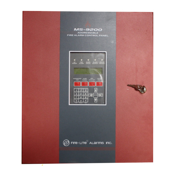
1.0 Description 1.0 Description The Fire•Lite MS-9200 is a compact, cost effective, addressable Fire Alarm Control Panel (FACP) with an extensive list of powerful features. The combination of Fire•Lite's 300 Series Addressable Devices and the MS- 9200 Fire Alarm Control Panel offers the latest in Fire Protection Technology. The power supply and all electron- ics are contained on a single circuit board housed in an attractive metal cabinet, providing a complete fire control system for most applications. -
Page 8: Specifications
Normal Flat Charge—27.6V @ .8 amp. Maximum Battery Capacity: 17 AH. 1) Up to 7 AH batteries can be housed in the MS-9200 enclosure. 2) 12 to 17 AH batteries require the Fire•Lite BB-17F or similar UL listed battery cabinet. -
Page 9: Controls And Indicators
LCD DISPLAY LCD DISPLAY LCD DISPLAY LCD DISPLAY The MS-9200 uses a 40 character (2 lines X 20 characters), high viewing angle, LCD display, with a SYSTEMS ALL NORMAL character height of 3/16". The display includes a long-life LED backlight that remains illuminated. If AC... -
Page 10: Components
CABINET CABINET The MS-9200 cabinet is red with an attractive navy blue front overlay. The backbox measures 15" x 14.5" x 2.625" and provides space for two batteries (up to 7 amp-hours). Ample knockouts are provided for system wiring. Also available is an optional dress panel, DP-9200, which mounts to the inside of the cabinet (required and included on the ULC version). - Page 11 CP300 Ionization smoke detectors. The detectors communicate with the main circuit board CPU via an SLC loop. The MS-9200 CPU determines the alarm, maintenance, or normal status of each device. Each detector responds to an address that is manually set via built-in rotary decimal switches. Each detector head has a removable plug-in connector for ease of wiring and maintenance (or service), as well as a single LED and test connections.
- Page 12 Addressable Devices: Modules (continued) Addressable Devices: Modules (continued) Addressable Devices: Modules (continued) Addressable Devices: Modules (continued) Addressable Devices: Modules (continued) C304 C304 C304 C304 C304 Addressable Control Module Addressable Control Module The C304 is an Addressable Control Module Addressable Control Module Addressable Control Module that can be used as a Notification Appliance or Speaker Circuit for powering and supervising compatible, UL listed Notification Appli- ances.
-
Page 13: Optional Interface Modules
See Figure 2.29 for information on connections and System Edit in the Programming/Read Status Section of this manual for information on programming the MS-9200 for use with a printer or PC. (This option is not available simultaneously with use of the DIM-485/LCD-40). -
Page 14: Accessories
The ZDM-16F mounts to the back of the membrane switch panel with 2 screws and connects by cable to J12 on the MS-9200 main circuit board. Sixteen individual red LEDs on the module annunciate alarms for the first sixteen software zones. - Page 15 With the breaker at the main power distribution panel turned off, connect the primary Hot line to Terminal 1 on the R45-24E and the primary Neutral line to Terminal 2. All connections between the MS-9200 and the R45-24E must be made in conduit, using #14 AWG wire. Do not route 240 VAC wiring in the same conduit as other control panel circuits.
- Page 16 The LCD-40 is a compact, attractive, 40-character backlit LCD fire annuncia- tor that is capable of displaying English-language text. It mimics the display on the MS-9200 main control circuit board and will annunciate device type, point alarm, trouble or supervisory condition, zone assignment plus any custom alpha labels programmed into the control panel.
- Page 17 (refer to Appendix D for detailed wiring requirements and System Edit in the Programming/Read Status Section of this manual for information on programming the MS-9200 for annunciator use) The LDM Series Lamp Driver Modules, which consist of the LDM-32F master and LDM-E32F expander modules, are used to provide an interface to a custom graphic LED annunciator.
- Page 18 Accessories: System Power Expansion - FCPS-24FE Remote Field Charger Power Supply Accessories: System Power Expansion - FCPS-24FE Remote Field Charger Power Supply Accessories: System Power Expansion - FCPS-24FE Remote Field Charger Power Supply Accessories: System Power Expansion - FCPS-24FE Remote Field Charger Power Supply Accessories: System Power Expansion - FCPS-24FE Remote Field Charger Power Supply The FCPS-24FE is a compact, remote power supply with battery charger.
-
Page 19: General
II I II I II I II I II I ALLA ALLA TION TION NSTALLA ALLA ALLATION TION TION 2.0 General General General General General Carefully unpack the system and check for shipping damage. Mount the cabinet in a clean, dry, vibration-free area where extreme temperatures are not encountered. - Page 20 x Mounting x Mounting 2.2 Bac Backbo kbox Mounting x Mounting x Mounting Remove the main PC board assembly by unscrewing the four screws in the corners of the board. Two standoffs support the board in the center. Set the board aside in a safe, clean place.
-
Page 21: Power
BATTERY POWER BATTERY POWER Observe polarity when connecting the battery. Connect the battery cable to J3 on the MS-9200 main circuit board using the plug-in connector provided. See Appendix A for calculation of the correct battery rating. CAUTION: Battery contains sulfuric acid which can cause severe burns to the skin and eyes, and can destroy fabrics. If contact is made with sulfuric acid, immediately flush the skin or eyes with water for 15 minutes and seek immedi- ate medical attention. -
Page 22: Standard Relays
The MS-9200 provides a set of Form-C alarm and a set of Form-C trouble contacts rated for 2.0 amps @ 30VDC (resistive). The panel also provides a Form-A supervisory contact rated for 2.0 amps @ 30VDC (resistive). -
Page 23: Rtm-8F Wiring
0.25" away from any nonpower-limited circuit wiring. Furthermore, all power-limited circuit wiring and nonpower-limited circuit wiring must enter and exit the cabinet through different knockouts and/or conduits. A typical wiring diagram for the MS-9200 is shown below. Figure 2.4: Typical Wiring Diagram for UL Power-limited Requirements Figure 2.4: Typical Wiring Diagram for UL Power-limited Requirements... -
Page 24: Wiring The Signaling Line Circuit
DEVICE CAPACITY DEVICE CAPACITY The capacity of each MS-9200 includes up to 99 addressable detectors, and an additional combination of up to 99 addressable pull stations, control modules and monitor modules. In addition, the panel supports 2 Notification Appliance (Bell) Circuits. - Page 25 Figure 2.5: Style 4 Wiring: T-tapping Restrictions and Branch Resistance Figure 2.5: Style 4 Wiring: T-tapping Restrictions and Branch Resistance Figure 2.5: Style 4 Wiring: T-tapping Restrictions and Branch Resistance Figure 2.5: Style 4 Wiring: T-tapping Restrictions and Branch Resistance Figure 2.5: Style 4 Wiring: T-tapping Restrictions and Branch Resistance T-tapping of the SLC loop wiring is allowed for two wire (Style 4) configurations.
- Page 26 Figure 2.7: Two-Wire Communications Loop (Supervised and Power-Limited) Figure 2.7: Two-Wire Communications Loop (Supervised and Power-Limited) Figure 2.7: Two-Wire Communications Loop (Supervised and Power-Limited) Figure 2.7: Two-Wire Communications Loop (Supervised and Power-Limited) Figure 2.7: Two-Wire Communications Loop (Supervised and Power-Limited) (meets NFPA 72 Style 4 requirements - may be T-tapped) BG-10LX BG-10LX...
- Page 27 Figure 2.8: Four-Wire Communications Loop (Supervised and Power-Limited) Figure 2.8: Four-Wire Communications Loop (Supervised and Power-Limited) Figure 2.8: Four-Wire Communications Loop (Supervised and Power-Limited) Figure 2.8: Four-Wire Communications Loop (Supervised and Power-Limited) Figure 2.8: Four-Wire Communications Loop (Supervised and Power-Limited) (meets NFPA 72 Style 6 requirements - cannot be T-tapped) BG-10LX BG-10LX...
- Page 28 Zones 01 and 03. The isolator modules on either side of Zone 02 will open the Loop. Zone 01 will still operate from power on Loop Out and Zone 03 will operate from Loop Return. Since the MS-9200 will no longer be able to communicate with Zone 02, a trouble signal(s) will be generated for that device.
- Page 29 Figure 2.10: Shield Termination in No Conduit Figure 2.10: Shield Termination in No Conduit Figure 2.10: Shield Termination in No Conduit Figure 2.10: Shield Termination in No Conduit Figure 2.10: Shield Termination in No Conduit MS-9200 MS-9200 MS-9200 MS-9200 MS-9200...
-
Page 30: The Isolator Module
Note: Note: Note: Note: During a fault condition, the MS-9200 will register a trouble condition for each device isolated on the loop branch. Figure 2.13: Isolating Two-Wire Communications Loops Figure 2.13: Isolating Two-Wire Communications Loops Figure 2.13: Isolating Two-Wire Communications Loops Figure 2.13: Isolating Two-Wire Communications Loops... -
Page 31: M300 Monitor Module
COMMUNICATIONS LOOP CONNECTIONS Connect the MS-9200 Communications SLC Loop to M300 terminals 1 (-) and 2 (+). The M300 occupies one module address on the Loop. Use the rotary switches on the M300 to set the module to the required loop address. -
Page 32: M302 Monitor Module
COMMUNICATIONS SLC LOOP CONNECTIONS Connect the MS-9200 Communications SLC loop to M302 terminals 1(-) and 2(+). The M302 occupies one module address on the loop. Use rotary switches on the M302 to set the module to the required loop address. - Page 33 M300 M300 M300 detector power Loop Out supervision. (300 mA max.) 24V (+) TB4-5 SLC (+) TB6-3 24V (-) TB4-6 MS-9200 MS-9200 MS-9200 MS-9200 MS-9200 SLC (-) TB6-5 Document # 50428 Rev. B1 7/28/97 P/N 50428:B1 Technical Manuals Online! - http://www.tech-man.com...
- Page 34 M300 M300 supervision. Loop Out detector power (300 mA max.) 24V (+) TB4-5 SLC (+) TB6-3 MS-9200 MS-9200 MS-9200 MS-9200 MS-9200 24V (-) TB4-6 SLC (-) TB6-5 Note: ELR is not required when wiring Style D (Class A). Document # 50428 Rev.
- Page 35 M302 M302 M302 M302 four-wire smoke Loop Out supervision. detector power (300 mA max.) 24V (+) TB4-5 SLC (+) TB6-3 MS-9200 MS-9200 24V (-) TB4-6 MS-9200 MS-9200 MS-9200 SLC (-) TB6-5 Document # 50428 Rev. B1 7/28/97 P/N 50428:B1 Technical Manuals Online! - http://www.tech-man.com...
- Page 36 + + + + + supervision. M302 M302 M302 M302 M302 Loop Out 24V (+) TB4-5 SLC (+) TB6-3 24V (-) TB4-6 MS-9200 MS-9200 MS-9200 MS-9200 MS-9200 SLC (-) TB6-5 Document # 50428 Rev. B1 7/28/97 P/N 50428:B1 Technical Manuals Online! - http://www.tech-man.com...
- Page 37 COMMUNICATIONS LOOP CONNECTIONS COMMUNICATIONS LOOP CONNECTIONS Connect the MS-9200 Communications SLC Loop to C304 terminals 1 (-) and 2 (+). The C304 occupies one module address on the Loop. Set the rotary switches on the C304 to the particular Loop address required.
- Page 38 COMMUNICATIONS LOOP CONNECTIONS COMMUNICATIONS LOOP CONNECTIONS Connect the MS-9200 Communications SLC Loop to C304 Terminals 1(-) and 2(+). The C304 occupies one module address on the Loop. Set the rotary switches on the module to the particular Loop address required.
- Page 39 CAUTION! Do not loop wiring under any terminals. Break wire run to maintain Loop Out supervision. 24V (+) TB4-1 SLC (+) TB6-3 24V (-) TB4-2 SLC (-) TB6-5 MS-9200 MS-9200 MS-9200 MS-9200 MS-9200 Document # 50428 Rev. B1 7/28/97 P/N 50428:B1 Technical Manuals Online! - http://www.tech-man.com...
- Page 40 BG-10LX INSTALLATION BG-10LX INSTALLATION 1) Connect the MS-9200 Communications SLC Loop to terminal screws (+) and (-) on the BG-10LX. 2.) The BG-10LX is factory preset with address 00. Set the address for the pull station by using a screwdriver to turn the rotary address switches on the back of the unit to the appropriate settings.
- Page 41 INSTALLATION INSTALLATION INSTALLATION • Connect the MS-9200 Communications SLC Loop to Terminal (-) and Terminal (+) of the removable terminal block. • If an RA400Z Remote LED Annunciator is being employed, connect the RA400Z positive terminal to the RA+ terminal on the removable terminal block and the negative terminal to the RA(-) terminal on the removable block.
- Page 42 Optional Modules Optional Modules The MS-9200 supports option modules, using connectors J6, J11, J12 and J16 on the main board. There are five optional modules available for the MS-9200; the RTM-8F Relay/transmitter Module, PIM-24 Printer/PC Interface Module, the UDACT-F Universal Digital Alarm Communicator Transmitter, the DIM-485 LCD-40 Display Interface Module and the ZDM-16F 16 zone LED Module.
- Page 43 Mounting Inside MS-9200 Enclosure The MS-9200 must have firmware with a Part Number of 73580 or higher installed to allow use of the UDACT-F. Remove all power from the MS-9200 by disconnecting AC and batteries. Install the supplied standoffs (three nylon and one aluminum standoff) in the appropriate holes located on the right side of the MS-9200 main circuit board as illustrated in Figure 2.25.
- Page 44 Install 120 ohm EOL resistor (P/N: 71244) on TB1 terminals 3 & 4 if last or only device on EIA-485 line. MS-9200 Cabinet UDACT-F in ABS-8RF (shown with cover removed) MS-9200 Notes: 1) This arrangement allows use of the UDACT-F simultaneously with the RTM-8F module.
- Page 45 The ACM-8RF Module provides eight Form-C relays with contacts rated for 5 amps. When installed with an MS-9200 Fire Alarm Control Panel (FACP), the ACM-8RF Relay Control Modules provide relay activation for each of the 56 possible FACP zones plus special functions.
- Page 46 Figure 2.28: RTM-8F Option Module Installation Figure 2.28: RTM-8F Option Module Installation Figure 2.28: RTM-8F Option Module Installation Figure 2.28: RTM-8F Option Module Installation Figure 2.28: RTM-8F Option Module Installation Insert the three nylon standoffs (provided) into the holes located on the right-side edge of the main circuit board.
- Page 47 Figure 2.29: RTM-8F Relay Transmitter Module Figure 2.29: RTM-8F Relay Transmitter Module Figure 2.29: RTM-8F Relay Transmitter Module Figure 2.29: RTM-8F Relay Transmitter Module Figure 2.29: RTM-8F Relay Transmitter Module JP2 - Jumper Settings: Note: If relays are used as power- limited circuits, paste supplied Alarm/Trouble Polarity Reversal label to terminal block as indicated.
- Page 48 (This option is not available simultaneously with use of the DIM-485/LCD-40). CAUTION: DO NOT connect a printer or PC to the MS-9200 Fire Alarm Control Panel if a ground fault exists on the panel. Circuit damage may result.
- Page 49 SW1 Write Protect switch in the down position. SW1 is located on the lower right side of the MS-9200 main circuit board (see page 6). If the switch is in the up 'Write...
- Page 50 NOTE: There are two programming levels. Program Level 1 is for system configuration in which data relating to device types, zoning, messages, etc. is entered into the system memory. Program Level 2 is where a qualified operator can access features such as Disable, Clear History, Walktest, Time Change and Program Check.
- Page 51 3.1 Programming 3.1 Programming 3.1 Programming 3.1 Programming 3.1 Programming Press the ENTER key. The screen below will appear: 1=PROGRAMMING 2=RD STATUS 3=AC/BAT To enter the programming mode, press '1'. The display will read as follows: KEY IN 5 DIGIT PASSWORD, THEN ENTER Entering the Level 1 password (default 00000) will cause the following screen to appear: (Refer to Section 3.2) 0=CLR 1=AUTO 2=POINT...
- Page 52 3.2 Program Change - Level One When the correct password is entered, the MS-9200 will enter Level One program mode. In this mode, the trouble relay is activated and the System Trouble LED flashes (and cannot be changed to steady). The piezo sounder is off.
- Page 53 In most cases, adjective, noun descriptors and zone assignments will be added by using the following procedure. The MS-9200 will lead you through the program editing process. A blinking cursor moves through the fields as you press the RIGHT CURSOR key (the triangle to the right of ENTER). After moving into other fields, you may return to a previous field by pressing LEFT CURSOR.
- Page 54 Pressing the UP or DOWN cursor keys steps through the library. Once the UP or DOWN keys are pressed, the blinking cursor moves to the last character of the ADJECTIVE field, assuming that the user will next want to move beyond this field. Pressing a key on the 12-key pad changes the letter indicated by the blinking cursor.
- Page 55 As an example, the user could quickly enter 'FLR_3_ROOM_305' as follows: 1) The cursor is on the first letter of the ADJ field. Press the Zero key twice to display 'FLR3'. 2) With the cursor on the first letter of the NOUN field, press the Zero key twice to recall the display 'ROOM304'.
- Page 56 III. III. CONTROL MODULE AUTOPROGRAMMING CONTROL MODULE AUTOPROGRAMMING III. III. III. CONTROL MODULE AUTOPROGRAMMING CONTROL MODULE AUTOPROGRAMMING CONTROL MODULE AUTOPROGRAMMING A typical control module Autoprogram screen would be: PROGRM CONTROL CNN <ADJ> Znn Znn Znn Control modules default to zone Zone 00 (general alarm). All type code options are silenceable except Relay and Strobes.
- Page 57 3.2.04 3.2.04 System Edit System Edit 3.2.04 3.2.04 3.2.04 System Edit System Edit System Edit The System Edit function is selected by pressing '3'. The system edit screen appears as shown below for software releases prior to P/N 73750. This software does not support the LCD-40 Annunciator: VF=N SI=N AS=N PS=N CD=N AN=N ST=4 REM=N Use the Up and Down arrow keys to scroll through the choices for each option and the Left and Right arrow keys to...
- Page 58 There are nine system function options for software P/N 73750 or greater. The factory default selections and user option selections are shown below: FUNCTION DEFAULT SELECTION V = Alarm Verification (N)one (Y)120 seconds I = Silence Inhibit (N)one (Y)60 seconds A = Auto-Silence (N)one (Y)10 minutes...
- Page 59 While displaying the Program Menu, program selection '5' sets up the MS-9200 for transfer of its application database from/to a DOS-based computer. This may be used to save the program that exists in an MS-9200 for security and future service reasons; or may be used to transfer a program created off-line to the MS-9200. Refer to Document# 15677 for more information.
- Page 60 Enter the Level 2 password (default = 11111) then press the ENTER key to access Programming Change Level Two. The screen below will appear: 1=DISABL 2=CLR HIST 3=WALK 4=TIME 5=CHEK From this screen, the available function choices include point DISABLE, CLEAR HISTORY, WALKTEST, SET TIME and CHECK programming.
- Page 61 3.3.03 3.3.03 3.3.03 Walk Test 3.3.03 3.3.03 Walk Test Walk Test Walk Test Walk Test If '3' is pressed, followed by ENTER, the following is displayed: WALK TEST 1-SILENT 2-PULSE SOUNDERS Press '1' to perform a silent walktest with all sounding devices, control modules and the bell 1 and bell 2 outputs OFF.
- Page 62 Check Check Program selection '5' performs a check on software zone assignments. The MS-9200 looks for output devices assigned to a software zone that does not contain any input devices (detectors, monitor modules). If multiple devices fail the check, the UP/DOWN keys are used to step through the list of devices. The user must return to point editing to correct any errors.
- Page 63 PERA TING NSTR NSTR UCTIONS Figure 4.1: The MS-9200 Membrane Switch Panel Figure 4.1: The MS-9200 Membrane Switch Panel Figure 4.1: The MS-9200 Membrane Switch Panel Figure 4.1: The MS-9200 Membrane Switch Panel Figure 4.1: The MS-9200 Membrane Switch Panel...
- Page 64 SYSTEMS ALL NORMAL 10:00 A MON 03/04/96 The MS-9200 performs the following functions at regular intervals while in normal mode: • Polls all devices on SLC loop. Checks for valid reply, alarms, troubles, etc. • Monitors AC input voltage and battery capacity.
- Page 65 T T T T T roub roub roub le Oper le Oper ation ation roub rouble Oper le Oper le Operation ation ation With no alarms, the detection of a trouble in the system will cause the piezo to sound, the System Trouble LED to flash, and the trouble relay to activate.
- Page 66 . If the ACKNOWLEDGE/STEP key is pressed, the display stops on the present item for one minute, or until the ACKNOWLEDGE/STEP key is pressed again. As the AC- KNOWLEDGE/STEP key is pressed, the MS-9200 displays events in the following priority order: Alarms, in order of address...
- Page 67 There are two Notification Appliance (bell) Circuits on the MS-9200. For software releases prior to P/N 73750, NAC 1 is programmable and factory defaulted to general alarm, silenceable and March Time coding operation. NAC 2 is not programmable and is fixed as general alarm, nonsilenceable and may not perform coded functions.
- Page 68 REAL TIME CLOCK OPERATION The MS-9200 includes a crystal time base clock that provides time of day, date, and day of week. Time is displayed as 12 hour time with month/day/year, and is stored in RAM. If both AC and battery power are lost, the time must be reset.
- Page 69 4.11 4.11 4.11 4.11 4.11 Presignal Presignal Presignal Presignal Presignal Presignal is used to delay output activation (control modules and NACs) while allowing for visual verification by a person. Once a detector or monitor module triggers an alarm, the onboard piezo sounds immediately, but the Notification Appliance (bell) Circuits are not activated for 15 seconds.
- Page 70 Read Status Read Status functions do not require a password. The MS-9200 will continue to provide fire protection while in read status mode . Read status may be entered while in alarm or trouble. If a new alarm or trouble occurs during these functions, the Read Status is aborted to prevent confusion.
- Page 71 READ HISTORY: READ HISTORY: The MS-9200 has a 500-event history buffer. Stored events include Point Status, System Troubles, and ACKNOWLEDGE/STEP, ALARM SILENCE, DRILL and SYSTEM RESET key presses. All events are recorded with the time and date. History events are stored in volatile memory, therefore, removal of primary AC power and secondary battery power will clear the history buffer.
- Page 72 Circuit anch Circuit anch Circuit anch Circuit The MS-9200 requires connection to a separate dedicated AC branch circuit (240 VAC), which must be labeled FIRE ALARM. FIRE ALARM. FIRE ALARM. FIRE ALARM. This branch circuit must connect to the line side of the main power feed of the FIRE ALARM.
- Page 73 Supply er Supply The MS-9200 provides regulated power for operating the fire alarm control panel, operating external de- vices, and operating the standby battery. The power for operating external devices is limited. Use Table A- 2A (standby or non-alarm) and Table A-2B (alarm) to determine if external loading is within the capabilities of the MS-9200 power supply.
- Page 74 Table A-2B: Regulated Load in Alarm Table A-2B: Regulated Load in Alarm Table A-2B: Regulated Load in Alarm @24 VDC @24 VDC @24 VDC @24 VDC @24 VDC Table A-2B: Regulated Load in Alarm Table A-2B: Regulated Load in Alarm External Devices connected to TB2 and TB4 # f o # f o...
- Page 75 Total Ampere Hours (AH) Required NOTE: 1) 7 AH battery can be located in the MS-9200 Backbox. 2) 12 AH and 17 AH batteries require the Fire•Lite BB-17F Battery box. 3) 20 AH to 55 AH batteries require the Fire•Lite R45-24E Charger for housing and charging batteries.
- Page 76 'software zones'. Setup of an MS-9200 software zone is straightforward. Any zone may have a minimum of one and a maximum of 99 addressable input devices. Each detector is automatically assigned to a general alarm output. A zone may also have a minimum of one and a maximum of 99 addressable output devices.
- Page 77 SD300 SD300 SD300 SD300 SD300 SD300 SD300 SD300 SD300 SD300 ZONE ZONE ZONE ZONE ZONE C304 C304 C304 C304 C304 M300 M300 M300 M300 M300 C304 C304 C304 C304 C304 M301 M301 M301 M301 M301 C304 C304 C304 C304 C304 CP300 CP300 CP300...
- Page 78 DETECTOR ZONE D E V I C E Z O N E Characters) A D D R E S S A D D R T Y P E N U M B E NOUN Characters) S D 3 0 0 FIRST HALL S D 3 0 0...
- Page 79 MONITOR/CONTROL MODULE ADJ (Up to 5 Characters) D E V I C E Z O N E A D D R E S S NOUN (Up to 10 A D D R T Y P E N U M B E R C h a r a c t e r s ) M 3 0 0 WEST...
- Page 80 Document # 50428 Rev. B1 7/28/97 P/N 50428:B1 Technical Manuals Online! - http://www.tech-man.com firealarmresources.com...
- Page 81 DETECTOR ZONE D E V I C E Z O N E Characters) A D D R E S S A D D T Y P E N U M B E NOUN Characters) Document # 50428 Rev. B1 7/28/97 P/N 50428:B1 Technical Manuals Online! - http://www.tech-man.com firealarmresources.com...
- Page 82 MONITOR/CONTROL MODULE D E V I C E Z O N E Characters) A D D R E S S A D D T Y P E N U M B E NOUN Characters) Document # 50428 Rev. B1 7/28/97 P/N 50428:B1 Technical Manuals Online! - http://www.tech-man.com firealarmresources.com...
- Page 83 (Note that older MS-9200 circuit boards do not have a hole near J11, thus preventing the insertion of the standoff). Align the connector on the DIM-485 board with J11 on the MS-9200 main circuit board and align the hole on the DIM-485 with the standoff inserted into the main circuit board.
- Page 84 LDM Series annunciators may be used in a similar manner. All drawings show power supplied to annunciators by the MS-9200. For system applications requiring greater than the 300 ma of nonresettable power the MS-9200 can supply, use the Fire•Lite FCPS-24FE Field Charger Power Supply.
- Page 85 A+ A- A+ A- OPTION PRINTER & UP/DOWN LOAD MS-9200 RIBBON CABLE The configuration shown above provides: 56 Zones of alarm indication, a system Trouble LED, an On Line/ Power LED, local piezo, and a Local Silence/Acknowledge switch. AFM-16ATF + - + - + -...
- Page 86 FIRE ALARM ANNUNCIATOR ALARM ZONE 1 ALARM ZONE 1 ALARM ZONE 1 ALARM ZONE 2 ALARM ZONE 2 ALARM ZONE 2 MS-9200 ALARM ZONE 3 ALARM ZONE 3 ALARM ZONE 3 ALARM ZONE 4 ALARM ZONE 4 ALARM ZONE 4...
- Page 87 CABLE + - + - + - N O C N O N C C N O N C C A+ A- A+ A- OPTION PRINTER & UP/DOWN LOAD MS-9200 Receive Only No Control Switches AFM-16ATX AEM-16ATF AEM-16ATF AEM-16ATF RIBBON...
- Page 88 EQUIREMENTS EQUIREMENTS The Fire-Lite MS-9200 has been designed for use in commercial, industrial, and institutional applications and meets the requirements for service under the National Fire Protection Association (NFPA) Standards outlined in this Appendix. The minimum system components required for compliance with the appropriate NFPA standard are listed below.
- Page 89 2) Program the MS-5012 for slave application. 3) SW2 Trouble/No AC switch located on bottom right of MS-9200 main circuit board, must be positioned in the down position for this application. This prevents the transmission of a trouble on the loss of AC power.
- Page 90 NOTES: 1) 3 ohms maximum loop resistance allowed for wiring from control panel to Municipal Box. 2) Cut JP4 on MS-9200 System Board to supervise placement of RTM-8F Module and circuit. MUNICIPAL BOX CONNECTED TO RTM-8F RELAY TRANSMITTER MODULE MUNICIPAL BOX CONNECTED TO RTM-8F RELAY TRANSMITTER MODULE...
- Page 91 Remote Station Connection Using RTM-8F Module Remote Station Connection Using RTM-8F Module Remote Station Connection Using RTM-8F Module Note: Cut Jumper JP-4 on MS-9200 System Board to supervise placement of the RTM-8F module.. Fire-Lite RS82 Remote Station Receiver UL listed.
- Page 92 Form-A relay contact programmed to activate on Supervisory condition. 2 2 2 2 2 Notes: 1) Connection between MS-9200 and the transmitter are supervised by the transmitter. 2) This MS-9200/Transmitter arrangement can be employed for NFPA 72D Proprietary Protective Signaling System.
- Page 93 Connecting external system accessories to the MS-9200 main circuits must be carefully considered to ensure proper operation. It is important to use the correct type of wire, wire gauge, and wire run length per each MS-9200 circuit. Reference the chart below to specify wire requirements and limitations for each MS-9200 circuit.
- Page 94 They can be placed on circuits to reduce the possibility of damage to sensitive equipment due to unexpected voltage surges. Table G-1 lists the surge suppressors which have been tested with the MS-9200 and have been found capable of reducing the risk of damage to the corresponding circuits due to voltage fluctuations.
- Page 95 APPENDIX H: APPENDIX H: SCREEN OPTIONS FLO SCREEN OPTIONS FLO WCHAR WCHAR WCHAR T T T T T APPENDIX H: SCREEN OPTIONS FLO SCREEN OPTIONS FLO WCHAR APPENDIX H: APPENDIX H: SCREEN OPTIONS FLO WCHAR (Software P/N 73750 or greater) Trouble in System Trouble in System Trouble in System...
- Page 96 Text inside box actually appears in LCD display Text inside oval indicates key press Write Protect Switch on Write Write Write Write Write MS-9200 motherboard Protect Protect Protect Protect Protect Document # 50428 Rev. B1 7/28/97 P/N 50428:B1 Technical Manuals Online! - http://www.tech-man.com...
- Page 97 Document # 50428 Rev. B1 7/28/97 P/N 50428:B1 Technical Manuals Online! - http://www.tech-man.com firealarmresources.com...
- Page 98 Document # 50428 Rev. B1 7/28/97 P/N 50428:B1 Technical Manuals Online! - http://www.tech-man.com firealarmresources.com...
- Page 99 Document # 50428 Rev. B1 7/28/97 P/N 50428:B1 Technical Manuals Online! - http://www.tech-man.com firealarmresources.com...
- Page 100 Limited Warranty Fire-Lite ® warrants its products to be free from defects in materials and workmanship for eighteen (18) months from the date of manufacture, under normal use and service. Products are date stamped at time of manufacture. The sole and exclusive obligation of Fire-Lite ®...
Need help?
Do you have a question about the MS-9200 and is the answer not in the manual?
Questions and answers