Table of Contents
Advertisement
Quick Links
Advertisement
Table of Contents

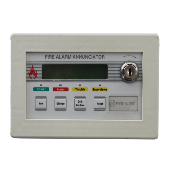
Summary of Contents for Fire-Lite Alarms LCD-40
- Page 1 The LCD-40 Remote Fire Annunciator for the Fire Lite • MS-9200 Addressable Fire Alarm Control Panel Document # 50327 3/26/96 Revision: P/N 50327:B ECN 96-117 12 Clintonville Road, Northford, CT 06472 Technical Manuals Online! - http://www.tech-man.com firealarmresources.com...
- Page 2 Technical Manuals Online! - http://www.tech-man.com firealarmresources.com...
-
Page 3: Table Of Contents
Figure 4-1: Power Connection ................13 Figure 4-2: EIA-485 Connection ................. 14 Figure 4-3: DIM-485 Connections ..............15 Figure 4-4: Wiring FACP to LCD-40 ..............16 Section Five: EIA-485 Shield Terminations ........... 17 When the EIA-485 Shield is not in Conduit ............17 When the EIA-485 Shield is in Full Conduit ............ -
Page 4: Section One: General Information
Supervisory conditions. The LCD-40 is also capable of performing system acknowl- edge, silence, drill and reset remotely. Communication between the control panel and the LCD-40 is accomplished over a two- wire serial interface employing the EIA-485 communication standard. Up to 32 LCD-40s may be connected to the two-wire EIA-485 circuit. - Page 5 Figure 1-2) Future use Top view Piezo Sounder The LCD-40 sounder, if enabled, will be activated Membrane Connector when any new alarm or trouble is received from the Cable connection to membrane switches panel. It is silenced by the ACKNOWLEDGE switch.
-
Page 6: Sw1 Dip Switch Settings
UP (OPEN) POSITION = OFF STATE NOTE - SW1 DIP switch settings as illustrated in Figure 1-2 are as follows: 1) DIP switch 1: ON (DOWN) = Receive/Transmit. This setting is used for the last or only LCD-40 on the EIA-485 loop. - Page 7 (Power supplies used for this purpose must have their negative terminals commoned together). 3) Between each LCD-40 are four wires: A twisted-shielded pair for data communications and a pair for 24 VDC power. The return circuit only requires two wires for data communication supervision, wired from the last or only LCD-40 on the loop.
-
Page 8: Section Two: Operation
• Upon power-up, the LCD-40 may display the following message until a valid message is received from the MS-9200. • If an LCD-40 fails to receive communications from the panel for a period of over 30 seconds, it will activate its local sounder (if so programmed) and display the following message: •... -
Page 9: Switch Functions
Subsequent pressing of the key 'steps' through each active event. Silence When the Silence key is pressed and released, the LCD-40 sends a Signal Silence command to the control panel. The Silence key performs the same functions as the Acknowledge key. -
Page 10: Drill Switch
ALARM SILENCE LED. The 'MANUAL EVACU- ATE' message is shown on the LCD-40 display. The same message is sent to the FACP display, printer and history files. The Silence key operates on silenceable NAC outputs only. -
Page 11: Section Three: Mounting
Never use the shield for grounding purposes. To mount the LCD-40 in the electrical box, the trim ring must first be removed. The trim ring is held in place by two screws inserted through the top and bottom edge as illus- trated. - Page 12 Set DIP switch SW1 for the desired options (refer to Figure 1-2). Carefully insert the LCD-40 into the three-gang electrical box and attach it using the four mounting holes on the LCD-40 flange and the four screws provided for this purpose.
-
Page 13: Section Four: Lcd-40 Electrical Connections
Section Four: LCD-40 Electrical Connections The LCD-40 can be powered by the MS-9200 power supply or from a remote UL listed, filtered, regulated power supply such as the Fire•Lite FCPS-24F. The power run to the LCD-40 must be power-limited but need not contain a power supervision relay since loss of power is inherently supervised through loss of communication with the LCD-40. - Page 14 1) All connections are power-limited and supervised. 2) A maximum of 32 LCD-40s may be connected to this circuit. 3) 6,000 feet maximum distance (@ 18 AWG) between the panel, LCD-40(s) and return to the panel. 4) Use overall foil/braided-shield twisted pair cable suitable for EIA-485 applications (refer to Section Five for shield termination information).
- Page 15 1) Terminal to terminal wiring is shown between the DIM-485 and one LCD-40. 2) If more than one LCD-40 is installed, the wiring to the DIM-485 In (+) Terminal 2 and In (-) Terminal 4 will be from the last installed LCD-40 (refer to Figure 4-4).
- Page 16 2) Six conductor overall shielded wire may be used for the four EIA-485 wires and the two power wires. It is, however, strongly recommended that the power and communication wires be separate whenever possible. Figure 4-4: Wiring FACP to LCD-40 Document 50327 Rev B...
-
Page 17: Section Five: Eia-485 Shield Terminations
FACP but must be left floating (no connection) at the LCD-40 if it is the first or only device on the EIA-485 loop. If a second LCD-40 is connected, the shield leaving the first LCD-40 must be left floating. The shield entering the second LCD-40 must be connected to the 3-gang box or Earth Ground terminal (P2-7) on the second LCD-40. -
Page 18: When The Eia-485 Shield Is In Full Conduit
FACP (both exiting and entering the FACP), but must be left floating (no connection) at the LCD-40 if it is the first or only device on the EIA-485 loop. If a second LCD-40 is connected, the shield leaving the first LCD-40 must be left floating. - Page 19 Document 50327 Rev B 3/26/96 P/N 50327:B Technical Manuals Online! - http://www.tech-man.com firealarmresources.com...
- Page 20 Limited Warranty ® Fire-Lite warrants its products to be free from defects in materials and workmanship for eighteen (18) months from the date of manufacture, under normal use and service. Products are date stamped at time of manufacture. The sole and exclusive obligation of Fire-Lite ®...


Need help?
Do you have a question about the LCD-40 and is the answer not in the manual?
Questions and answers