Table of Contents
Advertisement
Quick Links
Universal Digital Alarm Communicator/Transmitter
Technical Manuals Online! - http://www.tech-man.com
The UDACT-F
Product Information, Installation,
Programming and Operation Manual
12 Clintonville Road, Northford, CT 06472
firealarmresources.com
Document # 50049
Document # 50049
Document # 50049
Document # 50049
Document # 50049
D
5/2/97
5/2/97
5/2/97
5/2/97
5/2/97
Rev:
Rev:
Rev:
Rev:
Rev:
P/N 50049:D
ECN 97-173
© 1997 Fire•Lite Alarms, Inc.
Advertisement
Table of Contents

Subscribe to Our Youtube Channel
Related Manuals for Fire-Lite Alarms UDACT-F


Summary of Contents for Fire-Lite Alarms UDACT-F
- Page 1 The UDACT-F Universal Digital Alarm Communicator/Transmitter Product Information, Installation, Programming and Operation Manual Document # 50049 Document # 50049 Document # 50049 Document # 50049 Document # 50049 5/2/97 5/2/97 5/2/97 5/2/97 5/2/97 Rev: Rev: Rev: Rev: Rev: 12 Clintonville Road, Northford, CT 06472...
- Page 2 Technical Manuals Online! - http://www.tech-man.com firealarmresources.com...
-
Page 3: Table Of Contents
Figure 2-1: ABS-8RF Panel Mounting 2.2.1 MS-9200 Figure 2-2: UDACT-F Mounting to MS-9200 Figure 2-3: External UDACT-F Mounting in ABS-8RF 14 Table 2-1: Annunciator LED Assignments - MS-9200 15 2.2.2 Sensiscan 2000 Figure 2-4: UDACT-F Mounting in CHS-4 Figure 2-5: EIA-485 Connection Sensiscan 2000... - Page 4 Table 3-7: Ademco Contact ID, Secondary Number Operating Instructions Normal Mode 4.1.1 Keys 4.1.2 Displays Figure 4-1: UDACT-F Phone Connectors & LEDs 4.1.3 Normal Mode Operation 4.1.4 Key Report Descriptions Type Mode 4.2.1 Disabling of Zones or Points 4.2.2 Zone or Point Supervisory...
- Page 5 This control panel has been designed to comply with standards set forth by the following regulatory agencies: • Underwriters Laboratories Standard UL 864 • NFPA Standards 72-1993 Local, Remote Station and Central Station Fire Alarm Systems • CAN/ULC - S527-M87 Standard for Control Units for Fire Alarm Systems Before proceeding, the installer should be familiar with the following documents.
-
Page 6: Product Description
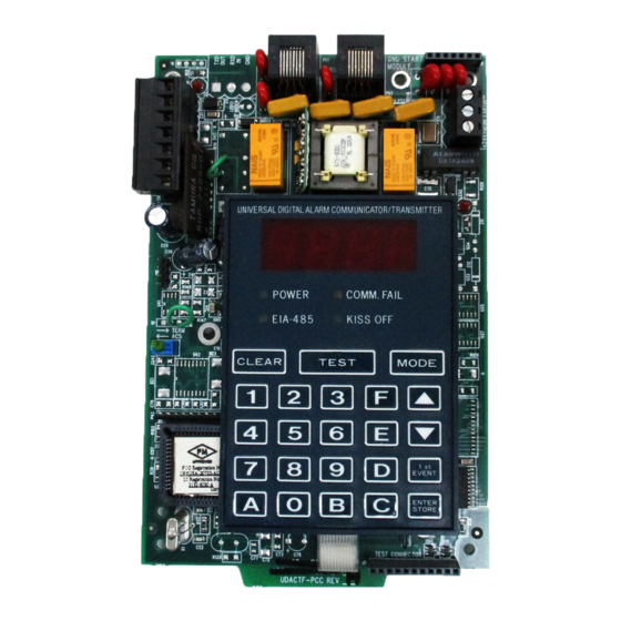
Sensiscan 2000 control panels. The UDACT-F transmits system status to UL Listed Central Station Receivers via the public switched telephone network. The UDACT-F is compact in size and may be mounted inside the host control panel or may mount externally in a separate enclosure. EIA-485 annunciator communications bus and 24 volt (nominal) connections are required. - Page 7 (use power-limited 24 VDC source) (power-limited) EIA-485 Connector (use power-limited source) Connector on back of board (Connect to J16 on MS-9200 only) Figure 1-1: UDACT-F Assembly Document # 50049 Rev D 5/2/97 P/N 50049:D Technical Manuals Online! - http://www.tech-man.com firealarmresources.com...
-
Page 8: Controls And Indicators
• Primary Phone Line Active - red LED • Secondary Phone Line Active - red LED • TEST - green LED Figure 1-2: Controls and Indicators Compatible The UDACT-F has been designed to be compatible with the following Fire-Lite control panels: Panels • Sensiscan 2000 • MS-9200. -
Page 9: Circuits
21.2 to 28.2 volts. The 24 VDC nominal operating power must be supplied by the Control Panel and is connected to TB1 of the UDACT-F. Note: If the UDACT-F is installed in an MS-9200 Control Panel, power is provided directly through UDACT-F connector J10 which plugs into the MS-9200 main circuit board. -
Page 10: Telephone Requirements And Warnings
TB3-1 = Earth Ground connection. Connect this terminal to building earth ground using solid 12 AWG wire to provide lightning protection. This connection is not required when the UDACT-F is mounted in an MS-9200 since the metal standoff used in mounting provides an earth ground connection. -
Page 11: For Canadian Applications
An FCC compliant telephone cord must be used with this equipment. This equipment is designed to be connected to the telephone network or premises wiring using a compatible RJ31X male modular plug which is Part 68 compliant. 1.7.4 For Canadian Applications The following is excerpted from CP-01 Issue 5: "NOTICE: The Canadian Department of Communications label identifies certified equipment. -
Page 12: Modes And Special Functions
Specific system trouble conditions and specific UDACT-F troubles are also transmitted. 1.8.2 Program Mode: Program mode is used to program the UDACT-F. While the UDACT-F is in the program mode, it cannot receive host FACP status information. See Section 3.0 for complete programming instructions. -
Page 13: Installation
MS-9200 main circuit board as illustrated in Figure 2-2. Position J10 located on the back of the UDACT-F over connector J16 which is located center right on the main MS-9200 circuit board, and carefully connect. - Page 14 6) Connect Ground Strap (supplied with ABS-8RF enclosure) from Earth Ground terminal on UDACT-F to a solid building earth ground. Conduit alone will not provide a reliable earth ground. 7) UDACT-F may be located up to 6000 feet away from the host control panel.
- Page 15 Caution: Connecting a UDACT-F to an MS-9200 which also has an AFM or LDM series annunciator connected will alter the assignments of the first eight yellow LEDs on the annunciator as follows: MS-9200 Yellow Annunciator LED Assignment Assignment Without UDACT-F...
-
Page 16: Sensiscan 2000
Connect the communication line between the EIA-485 terminal block on the CPU-2000 and TB-1 terminals 3 and 4 on the UDACT-F being certain to observe polarity (refer to Figure 2-5). Recommended wire is 12 AWG to 18 AWG twisted pair. If no other devices are connected to the EIA-485, install a 120 ohm EOL resistor across UDACT-F TB1 terminals 3 and 4. - Page 17 EIA- 485 line. Note that Terminals 6 (RS+) & 7 (RS-) are not used at this time. CPU-2000 UDACT-F Figure 2-5: EIA-485 Connection Sensiscan 2000 Document # 50049 Rev D 5/2/97 P/N 50049:D Technical Manuals Online! - http://www.tech-man.com firealarmresources.com...
- Page 18 UDACT UDACT-F MPS-24BF Note: Power for the UDACT-F must be 24VDC filtered, regulated non-resettable. Figure 2-6: 24VDC Power Connection to UDACT-F Document # 50049 Rev D 5/2/97 P/N 50049:D Technical Manuals Online! - http://www.tech-man.com firealarmresources.com...
- Page 19 Caution: Connecting a UDACT-F to a Sensiscan 2000 which also has an AFM or LDM series annunciator connected will alter the assignments of the first eight yellow LEDs on the annunciator as follows: Sensiscan 2000 Yellow Annunciator LED Assignment Assignment...
-
Page 20: Ul Power-Limited Wiring Requirements
Wiring nonpower-limited circuit wiring. Furthermore, all power-limited circuit wiring and Requirements nonpower-limited circuit wiring must enter and exit the cabinet through different knockouts and/or conduits. A typical wiring diagram for the UDACT-F is shown below. Use power- limited source... -
Page 21: Output Circuits
RJ31X style interconnection. (RJ31X jacks must be ordered separately). Note: It is critical that the UDACT-F be located as the first device on the incoming telephone circuit to properly function. - Page 22 Wiring from the UDACT-F terminal TB3 to the relay must be in the same room no more than 20 feet in length and enclosed in conduit. Wiring from the relay output contacts must also remain in the same room as the UDACT-F.
- Page 23 Wiring in same room as UDACT All wiring to relay must be in the 3.9K same room within 20 feet of Resistor UDACT-F and in conduit. (supplied) Earth Grnd Comm Fail +24 VDC MR-101/C UDACT (MR-201/C may also be used) Note: 1) M-300 Series Monitor Module is used to supervise Normally Closed output of MR-101/C.
-
Page 24: Programming Instructions
Continue to communicate any events not previously acknowledged at the Central Station prior to entering Programming Mode. Location 56 is factory set to = 0, UDACT-F communications disabled. This keeps the communicator off until location 56 is changed to 1, 2, 3, 4, 5 or 6. Refer to program selection for address 56 in this section. -
Page 25: Switch Functions
Twice = type any address are 0 to 9 and A - Save data, go to next address to F Figure 3-1: UDACT-F Keypad Programming Primary phone number. (00-15) Options The first sixteen addresses, 00-15, are factory set to 'F' (from 00_F to 15_F). - Page 26 F: Not Used Note: Consult your Central Station for proper selection or consult our factory representatives. For any format chosen, the UDACT-F automatically programs all of the event codes. See Tables 3-2, 3-3, 3-4, 3-5, 3-6 and 3-7. Primary Number Account Code (17-20) Four locations at addresses 17-20 default to all '0's.
- Page 27 1=12 hours. Use the Start and End Monitoring Address programming locations to set the reporting range of the UDACT-F. Start Monitoring Address (52-53) is programmed to indicate the first group of zones or points to be monitored and reported to the Central Station. Default is '01'.
- Page 28 EIA-485 communications bus supervision. Use the receive/transmit entries when annunciators are not installed or when the UDACT-F receive/transmit function is to be used to supervise the EIA-485 communication bus. For additional information on the receive/transmit function, refer to annunciator technical manuals.
- Page 29 Exit Programming Mode by pressing MODE, followed by the 4-digit code corresponding to an alternate mode of operation, then press [ENTER/STORE]. During Program Mode, if no key is pressed within 10 minutes, the UDACT-F will revert to normal mode. Document # 50049 Rev D 5/2/97 P/N 50049:D Technical Manuals Online! - http://www.tech-man.com...
- Page 30 Primary # Comm. Trouble Secondary Number Restore Code E Primary # 485 Comm. Trouble Restore Code Primary # System Off Normal Restore Code Primary # UDACT-F Off Normal Restore Code Primary # System 24 Hour Test Primary # System 24 Hour Test w/active event Primary # Manual Test Note: Zero entries prevent the transmission of the report to the Central Station.
- Page 31 Primary # 485 Comm. Trouble Restore Code 129 - 130 Primary # System Off Normal Restore Code 131 - 132 Primary # UDACT-F Off Normal Restore Code 133 - 134 Primary # System 24 Hour Test 135 - 136 Primary # System 24 Hour Test w/active events...
- Page 32 1) Note: Zero entries prevent the transmission of the report to the Central Station. 2) Refer to Contact ID program locations 64 - 68. 3) The identification of the zone/sensor number is automatically transmitted by the UDACT-F and is added to the main event code. See Appendix A-3 for more information.
- Page 33 Secondary # Comm. Trouble Secondary # Restore Code Secondary # 485 Comm. Trouble Restore Code Secondary # System Off Normal Restore Code Secondary # UDACT-F Off Normal Restore Code Secondary # System 24 Hour Test Secondary # System 24 Hour Test w/active event Secondary # Manual Test Note: Zero entries prevent the transmission of the report to the Central Station.
- Page 34 Secondary # 485 Comm. Trouble Restore Code 199 - 200 Secondary # System Off Normal Restore Code 201 - 202 Secondary # UDACT-F Off Normal Restore Code 203 - 204 Secondary # System 24 Hour Test 205 - 206 Secondary # System 24 Hour Test w/active events...
- Page 35 1) Note: Zero entries prevent the transmission of the report to the Central Station. 2) Refer to Contact ID program locations 64 - 68. 3) The identification of the zone/sensor number is automatically transmitted by the UDACT-F and is added to the main event code. See Appendix A-3 for more information.
- Page 36 [ENTER/STORE] key. TEST If the Test Key is pressed three times in rapid succession the UDACT-F will transmit a test message to both Central Stations. The message reported is the same as the automatic test message for all formats except Ademco Contact ID.
- Page 37 1st EVENT This key along with the Up Arrow and Down Arrow keys, are used to display UDACT-F fault conditions. Press the 1st Event key at any time to display the first event that occurred. DOWN ARROW Use the Down Arrow key to view other UDACT-F fault events (older) that have occurred and are active - not cleared yet.
- Page 38 The display will only annunciate UDACT-F trouble conditions in the normal mode. The UDACT-F transmits zone/point and system status reports to a Central Station via the public switched telephone network. Two supervised telephone line connections are made to interface the UDACT-F to the telephone lines.
- Page 39 (TB3, terminal 2). Note that as an option, all reports may also be sent to the secondary phone number. Refer to Section 3.0 Programming Instructions. The UDACT-F meets NFPA 72 for Remote Station Protective Signaling Service and Central Station Signaling Service reporting requirements for: (a) the type of signal (b) condition and (c) location of the reporting premises.
- Page 40 (such as an alarm, trouble or supervisory condition) at the time when the test report is due to be transmitted, the UDACT-F will report the 'system abnormal test report.' If the system is normal, the report transmitted will be the normal 'system test report.'...
- Page 41 4.2.2 Zone or Point Supervisory A zone or point must be defined as supervisory to allow the UDACT-F to identify the correct report to transmit to the central station. Follow the programming instructions in the FACP manual to program a zone or point as supervisory.
- Page 42 Pressing C for touchtone dialing or D for rotary dialing, followed by [ENTER/ STORE] causes seizure of the Primary phone line which in turn lights the red LED signifying Primary phone line active. After a delay of three seconds, the UDACT-F goes off hook to acquire a dial tone.
- Page 43 Appendix A: Reporting Formats Table A-1 shows the data reporting structure for each of the pulsed formats as well as the Ademco Express formats. Ademco Express formats allow a typical data message to be transmitted to the Central Station in under 5 seconds. Pulsed formats typically require 15 to 20 seconds in comparison.
- Page 44 Where: SSS 0r SSSS = Subscriber ID = Alarm (1st digit) = Alarm (2nd digit) = Alarm Restore (1st digit) = Alarm Restore (2nd digit) = Zone Trouble (1st digit) = Zone Trouble (2nd digit) = Zone Trouble Restore (1st digit) RTZ2 = Zone Trouble Restore (2nd digit) = System Trouble (1st digit)
- Page 45 The reporting structure for the Ademco Contact ID format is as follows: SSSS 18 QXYZ GG CCC where SSSS = Four digit Subscriber ID (addresses 17 - 20 and 43 - 46) = Identifies transmission as Contact ID to the receiver at the Central Station = Event Qualifier E = New Event...
- Page 46 Point Reporting By using the Type Mode feature with address 56 set to 3, 4, 5 or 6, identifica- tion of each type of activated device is possible. Note that addressable detectors report as code 111. It should also be noted that the meaning of the first digit of the three digit zone/sensor number will depend on the Type Mode programmed in Address 56.
- Page 47 Appendix B: Compatible Receivers The chart below shows UL listed receivers compatible with the UDACT-F: Format # (Addresses 16 & 42) 4+1 Ademco Express 4+2 Ademco Express (5,6) 3+1/Standard/1800/2300 Not Used 3+1/Standard/1900/1400 Not Used 4+1/Standard/1800/2300 Not Used 4+1/Standard/1900/1400 Not Used...
- Page 48 Start Monitoring Address. End Monitoring Address. UDACT-F Communication Selection. Enter '0' to disable UDACT-F communication; '1' for zone report- ing receive only communication; '2' for zone reporting receive/transmit communication; '3' for point reporting receive only communication; '4' for point reporting receive/transmit communication; '5' for code wheel matching point reporting, receive only;...
- Page 49 Programming Reference Sheet Document # 50049 Rev D 5/2/97 P/N 50049:D Technical Manuals Online! - http://www.tech-man.com firealarmresources.com...
- Page 50 Secondary 24-Hour Test Time. 0000 = 12:00 midnight. Secondary Number Test Time Interval. '0' for 24-hour. Start Monitoring Address End Monitoring Address UDACT-F Communication Selection. '0' for UDACT-F Communication disabled. Backup Reporting. '0' for backup. Touchtone/Rotary Select. '0' for Touchtone. Make/Break Ratio. '0' for 67/33 make/break ratio.
- Page 51 Programming Reference Sheet Factory Default Document # 50049 Rev D 5/2/97 P/N 50049:D Technical Manuals Online! - http://www.tech-man.com firealarmresources.com...
- Page 52 Appendix D: Point Assignments (Address 56 = 3 or 4) Point Type Device Point Type Device Point Type Device Point Type Device ( D e t e c t o r s ) ( D e t e c t o r s ) ( M o d u l e s ) ( M o d u l e s ) 0 0 1...
- Page 53 Appendix E: Code Wheel Matching Point Assignments (Address 56 = 5 or 6) Point Type Device Point Type Device Point Type Device Point Type Device ( D e t e c t o r s ) ( D e t e c t o r s ) ( M o d u l e s ) ( M o d u l e s ) Note: Use chart to carefully identify all points in the system.
- Page 54 Appendix F: Zone Assignments Zone No. Zone Function Zone No. Zone Function Note: Use chart to carefully identify function of each zone in the system. Take special precaution with any supervisory zones in the system. Use Type Mode (refer to Section 4.2 Type Mode) to match the function of remaining zones in the system for proper reporting.
- Page 55 Document # 50049 Rev D 5/2/97 P/N 50049:D Technical Manuals Online! - http://www.tech-man.com firealarmresources.com...
- Page 56 Limited Warranty Fire-Lite ® warrants its products to be free from defects in materials and workmanship for eighteen (18) months from the date of manufacture, under normal use and service. Products are date stamped at time of manufacture. The sole and exclusive obligation ®...
Need help?
Do you have a question about the UDACT-F and is the answer not in the manual?
Questions and answers