Table of Contents
Advertisement
Technical Manuals Online! - http://www.tech-man.com
Control Communicator
Installation, Operation and
Programming Manual
12 Clintonville Road, Northford, CT 06472
firealarmresources.com
MS-5012
Document #15465
Document #15465
Document #15465
Document #15465
Document #15465
F
5/2/97
5/2/97
5/2/97
5/2/97
5/2/97
Rev:
Rev:
Rev:
Rev:
Rev:
P/N 15465:F
ECN 97-227
© 1997 Fire•Lite Alarms, Inc.
Advertisement
Table of Contents

Related Manuals for Fire-Lite Alarms MS-5012


Summary of Contents for Fire-Lite Alarms MS-5012
- Page 1 MS-5012 Control Communicator Installation, Operation and Programming Manual Document #15465 Document #15465 Document #15465 Document #15465 Document #15465 5/2/97 5/2/97 5/2/97 5/2/97 5/2/97 Rev: Rev: Rev: Rev: Rev: 12 Clintonville Road, Northford, CT 06472 P/N 15465:F ECN 97-227 © 1997 Fire•Lite Alarms, Inc.
- Page 2 Technical Manuals Online! - http://www.tech-man.com firealarmresources.com...
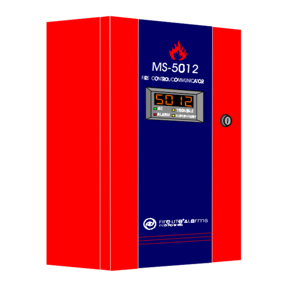
- Page 3 2.4 Digital Communicator Table 2.4-1: Format Selection Addresses Table 2.4-2: Compatible UL Listed Receivers Installation 3.1 Cabinet Figure 3.1-1: The MS-5012 3.2 Input Circuits Figure 3.2-1: Cabinet Dimensions Figure 3.2-1: Initiating Device Circuits 3.3 Output Circuits Figure 3.3-1: Output Circuits Figure 3.3-2: Relays...
- Page 4 This control panel has been designed to comply with standards set forth by the following regulatory agencies: Underwriters Laboratories Standard UL 864 NFPA Standard 72-1993 Local, Remote Station Fire Alarm Systems Before proceeding, the installer should be familiar with the following documents. NFPA Standards, NFPA 72-1993 National Fire Alarm Code: Installation, Maintenance, and Use of Central Station Fire Alarm Systems Local Fire Alarm Systems...
- Page 5 15465 Rev F 5/2/97 P/N 15465:F Technical Manuals Online! - http://www.tech-man.com firealarmresources.com...
- Page 6 The MS-5012 Panel Primary & Secondary Phone Lines Slot for Annunciator Piezo Driver Module 85dB 5 Input Zones 4-Digit LED Display Keypad 4 Open Collector Outputs Holds up to 7AH Batteries Up to 60 Hrs. of Standby 15465 Rev F 5/2/97 P/N 15465:F Technical Manuals Online! - http://www.tech-man.com...
-
Page 7: Product Description
1.0 Product Description The MS-5012 is a combination control panel and digital communicator all on one circuit board. It is a five-zone panel which uses conventional input devices. The panel accepts waterflow devices, two- wire smoke detectors, four-wire smoke detectors, pull stations and other normally open contact devices. -
Page 8: Front Panel Switches
1.2 Circuits Input Circuits Initiating Device Circuit 1 (Style B) N.O. contact devices only. Initiating Device Circuit 2 (Style B) N.O. contact devices, 2-wire smoke detectors. Initiating Device Circuit 3 (Style B/D) N.O. contact devices, 2-wire smoke detectors, waterflow devices. (2-wire detectors use Style B only) Initiating Device Circuit 4 (Style B) N.O. -
Page 9: Digital Communicator
1.5 Digital Digital Communicator The integral digital communicator provides the following functions: Communicator Line Seizure - takes control of the phone lines disconnecting any premises phones. Off/On Hook - perform on and off-hook status to the phone lines. Listen for dial tone - 440 hertz tone typical in most networks. Dialing the Central Station(s) number - default is Touch-Tone®, programmable to rotary. - Page 10 1.6 Optional ADM-12 Annunciator Driver Module The ADM-12 Annunciator Driver Module supports the RZA-5F Remote Boards Annunciator module. Annunciator wiring is supervised for open conditions by this module. The Annunciator Driver Module mounts to the main board, occupying one of the two option connectors. Connect ADM-12 to main board at J3.
-
Page 11: Specifications
AC Power Primary TB1 Terminals 1-2 1.8 Specifications 120VAC, 50/60 Hz, 0.32 A 15.0 VAC, 50/60 Hz, 2.0 amps, 25 VA Battery (sealed lead acid only) Connector J1 Maximum Charging Capacity: 14.3V, 0.80A Maximum Battery Capacity: 7AH Initiating Device Circuits TB2 Terminals 1-2, 9-10, 11-12 N.O. - Page 12 : Manufacturer : Fire·Lite Alarms Inc. 12 Clintonville Rd. Northford, CT 06492 Product Model Number: MS-5012 FCC Registration Number: 1W6USA-74525-AL-E Ringer Equivalence 0.0B Piezo Sounder An on-board piezo sounder will emit three distinctly different audible tones depending on system activity.
- Page 13 Telephone Company Rights and Warnings: The telephone company under certain circumstances may temporarily discontinue services and/or make changes in its facilities, services, equipment or procedures which may affect the operation of this control panel. However, the telephone company is required to give advance notice of such changes or interruptions.
-
Page 14: Control Panel Operation
2.0 Control Panel Operation Normal Mode The MS-5012 has six Modes of operation; Normal, Program, Walk Test, Lamp Test, Troubleshoot, and History. Upon initial power up, the system will be in Normal Mode. This section discusses operation of the control panel in the Normal Mode. Programming is discussed in Section 4. - Page 15 If the Silence Switch is pressed: The bell circuit will be turned OFF. The silence LED will be turned ON. The piezo sounder will be shut OFF. “System Silenced” message will be stored in the History file. Upon occurrence of a subsequent event (alarm or trouble), System Silence is overridden and the control panel will respond to the new event.
- Page 16 Individual LEDs are provided for: System Alarm—A red LED that lights when an alarm condition is detected. System Trouble—This yellow LED indicates that a fault or abnormal condition exists and that the fire alarm system may be inoperative. AC Power On—A green LED that remains on while the A.C. power supply is operating.
-
Page 17: Operation
2.3 Operation Normal mode is the standard mode of operation. In this mode, the panel continuously monitors system status. When no alarm or fault conditions exist, the display will be blank and all LEDs will be off (except the AC Power LED). The Notification Appliance Circuit will be off, all relay drivers are deactivated and the on-board piezo sounder will be off. - Page 18 Alarm Response The MS-5012 will upon detection of an alarm condition: Turn the alarm LED on. Activate the alarm relay driver. (TB3-4) Display an alarm message as follows: Alarm on zone 1 Alarm on zone 2 Alarm on zone 3...
- Page 19 Pulse the piezo sounder at 0.5 sec on 0.5 sec off rate. When the supervisory condition has been cleared (condition is restored and the reset switch has been pressed) the MS-5012 will perform the following: Turn off the supervisory LED .
- Page 20 Normal Mode causes a transmission of a "return to normal" restoral message. 2.4 Digital The MS-5012 transmits zone and system status reports to a Central Station via the public switched telephone network. Two supervised Communicator telephone line connections are made to interface the control panel to the telephone lines.
- Page 21 (TB3, terminal 7). Note that as an option, all reports may be sent to the secondary phone number. The MS-5012 meets NFPA 72-1993 for Central Station Signaling Service and for Remote Station Protective Signaling Service reporting requirements for: (a) the type of signal (b) condition (c) location of the reporting premises.
- Page 22 Where: SSS 0r SSSS = Subscriber ID = Alarm (1st digit) = Alarm (2nd digit) = Zone Number = Alarm Restore (1st digit) = Alarm Restore (2nd digit) = Zone Trouble (1st digit) = Zone Trouble (2nd digit) = Zone Trouble Restore (1st digit) RTZ2 = Zone Trouble Restore (2nd digit) = System Trouble (1st digit)
- Page 23 Transmittal Priorities The integral communicator transmits highest priority events first. Events in terms of priority are listed below in descending order: 1: Alarms (Highest Priority Level) Pull Stations Waterflow Smoke Detector Other Alarm Types 2: Supervisory Zone 3: Faults AC Fail Zonal faults Earth fault Low battery/No battery...
- Page 24 Central Station. The "Kissoff" LED may turn on several times during communications. The chart below shows UL listed receivers compatible with the MS-5012: Table 2.4-2: Compatible UL Listed Receivers Format # (Addresses 16 &...
-
Page 25: Installation
The MS-5012 3.2 Input Circuits The MS-5012 has five zone input circuits. The maximum loop resistance limit for each is 100 ohms. All field wiring of each zone is supervised for opens and ground faults. Both conditions are visually and audibly annunciated as well as communicated to a Central Station. - Page 26 Draw wires through the respective knockout locations. Dimensions: The door is 14.714" high x 12.714" wide. The backbox is 14.5" high x 12.5" wide x 2.875" deep. Metal gauge is 18. The metal finish is Fire-Lite standard red. Knock-outs are provided on the top and sides, to provide ease of wire entry.
- Page 27 Note: When zone 3 is programmed to accept 2-wire smoke detectors, it will only function as a NFPA Style-B initiating device circuit. See figure 3.2-1. Zone four is a Style B circuit designed as a Supervisory zone or may accept any N.O. contact device on TB2, terminals 9-10. As a Supervisory zone, the circuit may or may not be able to detect a supervisory alarm condition after the occurrence of an open in the loop wiring.
- Page 28 For example, default programming provides the following: when Zone 1 activates, it will be reported to the central station as “Manual Pull Station Alarm." For Zone 4 alarm, the report will be “Supervisory Alarm." For reporting formats that do not allow for detailed reports, the message will be: “Zone 1 alarm”...
- Page 29 UL Recognized Enclosure +13.8V General Alarm General Trouble Supervisory Communication Fail Relays Note: Wiring from TB3 to Relays is power-limited but not supervised. Figure 3.3-2: Driving Relays from Open Collector Outputs The control panel's open collector outputs on Terminal TB3 can be used to activate UL-864 listed remote relays.
- Page 30 0.25" away from any nonpower-limited circuit wiring. Requirements Furthermore, all power-limited circuit wiring and nonpower-limited circuit wiring must enter and exit the cabinet through different knockouts and/or conduits. A typical wiring diagram for the MS-5012 is shown below. Power-limited Circuits Power-limited...
- Page 31 3.5 Digital Two independent telephone lines can be connected to the MS-5012. Telephone line control/command is made possible via double line Communicator seizure as well as usage of an RJ31X style interconnection. Note: It is critical that the panel's digital communicator be located as the first device on the incoming telephone circuit to properly function.
-
Page 32: Operating Power
120 VAC, 50/60 HZ, 0.32A. Run a pair of wires from the protected premises main breaker box to the black and white primary leads of the MS-5012 system transformer. As per the National Electric Code, use 14 AWG (1.6 mm O.D.) or heavier gauge wire with 600V insulation wiring. - Page 33 CAUTION! Make certain all power (AC and battery) is removed before any connections are made. 1. Mount the optional AC terminal block to the lower left of the MS-5012 backbox using two supplied screws. 2. Connect AC power wiring to the optional terminal block as shown in Figure 3.6-2.
- Page 34 3.7 Optional ADM-12 Annunciator Driver Module Boards The Annunciator Driver Module supports the RZA-5F Remote Annunciator module. Annunciator wiring is supervised for open conditions by this module. The Annunciator Driver Module mounts to the main board, occupying one of the two option connectors. (See Section 1.6) The RZA-5F Remote Annunciator mounts on a standard single-gang box, and provides LED indication of the following:...
-
Page 35: Remote Annunciator
Remote Annunciator screw # 6-32 x 1.00" LG Figure 3.7-1: Installing the Annunciator in a Single Gang Box +12V Note: Make wiring connections with system power off. Maximum wire ADM-12 impedance is 100 ohm per wiring connection. RZA-5F Figure 3.7-2: Wiring the RZA-5F/ADM-12 15465 Rev F 5/2/97 P/N 15465:F Technical Manuals Online! - http://www.tech-man.com... -
Page 36: Programming Instructions
4.0 Programming Instructions Programming Programming of the MS-5012 is possible at any time except when an alarm condition is present in the Normal Mode of operation. Mode The MS-5012 has been designed for many different types of applications. After examining your specific application, review the programming options and choose the entries best suited for your system. - Page 37 When in Programming Mode, the trouble light will be on, the trouble relay driver will be activated, but the communicator will not be activated to report this trouble. Transmissions started before entering program mode will continue during programming. The first three locations from the left represent the memory address which can go from 00 up to 243 (Alpha characters are not used).
- Page 38 E: Not Used F: Not Used Note: Consult your Central Station for proper selection or consult our factory representatives. For any format chosen, the MS-5012 automatically programs all of the event codes. See the following tables. 15465 Rev F 5/2/97 P/N 15465:F Technical Manuals Online! - http://www.tech-man.com...
- Page 39 Table 4.3-1: 3+1 and 4+1 Standard and Expanded, 4+2 Expanded Formats If "2, 3, 4, 5, 6, 7, 8, 9, B or D" are entered for address 16, the following data is automatically programmed for the Primary phone number event codes. Enter '0' for the Setting to disable the report.
- Page 40 Table 4.3-2: 4+2 Standard Format If "A or C" are entered for address 16, the following data is automatically programmed for the Primary phone number event codes. Enter '00' for the Setting to disable the report. Address Description Settings 68-69 Primary # Zone 1 Alarm Code 70-71 Primary # Zone 2 Alarm Code...
- Page 41 Programming the Primary Number Account Code (17-20) takes up 17 0 four locations at addresses 17-20. The defaults are all "0"s. Valid entries are (0-9 and A-F). The number of digits entered must match the format selection. If programming "2, 3, 4, or 5" into address 16, enter 3 digits.
- Page 42 Table 4.3-3: 3+1 and 4+1 Standard and Expanded, 4+2 Expanded If "2, 3, 4, 5, 6, 7, 8, 9, B or D" are entered for address 42, the follow- ing is automatically programmed for the Secondary phone number event codes. Enter '0' for the Setting to disable the report. Factory Address Description...
- Page 43 Table 4.3-4: 4+2 Standard Format If "A or C" are entered for address 42, the following is automatically programmed for the Secondary phone number event codes. Enter '00' for the Setting to disable the report. Factory Address Description Setting 156-157 Secondary # Zone 1 Alarm Code 158-159 Secondary # Zone 2 Alarm Code...
- Page 44 1=7 hours, 2=8 hours, 3=9, 4=10, 5=11, and 6=12. Slave Communicator/Fire Panel Selection (56) Leaving address 56 at "0" means the MS-5012 is operating as a fire panel only. Selecting "1" will make it operate as a slave communicator only. See Section 6, Slave Communicator Configuration. Selecting "2"...
- Page 45 Alarm Verification on Detector Zones 2 and 3 (58) Factory Default setting for this address is "0" which means no alarm verification. Entering a "1" enables verification for zone 2 and zone 3. Consult local Authority Having Jurisdiction (AHJ) prior to altering this address.
- Page 46 Annunciator Present (63) Factory default is "0", no annunciator present. Changing address 63 to a "1" means that an annunciator is in use. Zone 4 Function Select (64) Zone 4 is factory set at "0" to be a Supervisory Zone. (Accepts N.O. Supervisory devices) Changing address 64 to "1"...
- Page 47 End Programming Exit Programming Mode by pressing , followed by the 4-digit code corresponding to an alternate mode of operation, then hit enter/store. During Program Mode, if no key is pressed within 10 minutes, the panel will revert to normal mode. Programming the Real-Time Clock Entering an address greater than 243 will cause a display of the current time.
- Page 48 5.0 Servicing 5.1 Walk Test Mode The MS-5012 provides the capability to perform a one-man walk test of the system without triggering the communicator or the alarm output relay driver. Walk Test allows for testing of the five zones (initiating circuits).
-
Page 49: History Mode
To return the MS-5012 to normal mode, press the mode key, the numbers 6676 and the key. Any delay between ENTER/STORE key entries greater than 10 seconds causes the control panel to remain in Walk Test Mode. The control panel will automatically revert back to Normal Mode if no system activity has occurred for 60 minutes. - Page 50 Shown below is the list of messages as they will appear on the display: DISPLAY EVENT Zone 1 Alarm Zone 2 Alarm Zone 3 Alarm Zone 4 Alarm Zone 5 Alarm 5uP4 Supervisory Alarm AC Loss Zone 1 Fault Zone 2 Fault Zone 3 Fault Zone 4 Fault Zone 5 Fault...
-
Page 51: Troubleshoot Mode
To get into the Troubleshoot Mode, press 8768 spells "TROU" on a Touch-Tone® ENTER/STORE. phone. Once in this mode, the MS-5012 will: Turn on the trouble LED. Energize/activate the trouble relay driver. Disable the Notification Appliance Circuit output. Disable the alarm relay driver. - Page 52 Pressing c causes seizure of the Primary line and the [ENTER/STORE] red LED signifying Primary line active turns on. After a delay of three seconds, the control panel goes off hook to acquire a dial tone. Connect- ing a telephone handset across the telephone transformer allows number dialing.
- Page 53 Programming Reference Sheet --- To enter Programming, press Mode: 7 7 6 4, Enter Addresses 00 to 15 store the Primary Phone Number. Enter "F" to represent the end of the number. Primary Comm Format: Enter 0 - F. Primary Account Code: Valid keys are 0-F. Primary 24-Hour Test Time.
- Page 54 Programming Reference Sheet 15465 Rev F 5/2/97 P/N 15465:F Technical Manuals Online! - http://www.tech-man.com firealarmresources.com...
- Page 55 Programming Reference Sheet Factory Default Settings --- To enter Programming, press Mode: 7 7 6 4, Enter. Addresses 00 to 15 store the Primary Phone Number. Enter "F" to represent the end of the number. Primary Comm Format:(4+2 Standard 1800/2300) Primary Account Code.
- Page 56 Programming Reference Sheet (Factory Default Settings) 15465 Rev F 5/2/97 P/N 15465:F Technical Manuals Online! - http://www.tech-man.com firealarmresources.com...
- Page 57 6.0 Slave Communicator Configuration The MS-5012 may be used as a slave communicator to a host or "Master" fire alarm control panel (FACP). Figure 6.0-1 shows a typical connection. All wiring between the Master and the MS-5012 is supervised. 2.2K End- Of-Line resistors should be connected as shown in Figure 6.0-1.
- Page 58 Inputs are supervised and power limited Relays in the Master FACP activate various input circuits on the MS-5012. Messages (event codes) programmed for a particular input circuit (channel) will be transmitted to the central station upon relay activation. 15465 Rev F 5/2/97 P/N 15465:F Technical Manuals Online! - http://www.tech-man.com...
-
Page 59: Appendix A: Power Calculations
Appendix A: Power Calculations Use the Total Standby and Alarm Load Currents calculated in Tables A-1 and A-2 for the following battery calculation. Standby Load Current Required Standby Time in Hours (24 or 60 (Amps) Hours) ___________ Required Alarm Time in Hours (i.e. 5 min. = Alarm Load Current (Amps) 0.084 hours) ___________... - Page 60 The MS-5012 provides regulated power for operating the fire alarm control panel, operating external devices, and operating the standby battery. The power for operating external devices is limited. Use Table A-1 (standby or nonalarm) and Table A-2 (alarm) to determine if external loading is within the capabilities of the power supply.
- Page 61 Table A-2: Regulated Load in Alarm @12 VDC Current Total Current Device Type # of Devices (Amps) (Amps) Main Circuit Board 0.170 0.170 ADM-12 (1 max.) 0.032 RZA-5F (1 max.) 0.030 4-wire Smoke Detector Power Supervision 0.025 Relay Auxiliary Outputs: TB3-4 Alarm (1 max.) 0.040...
- Page 62 Index ADM-12 Annunciator Driver Module 10, 33, 34 Optional Boards 10 Circuits 8, 11 Power Calculations 58 Clock 45 Primary Phone number 36 Programming Mode 35 Digital Communicator 9, 20, 31 Displays 8, 15, 35 Relays 29 Remote Annunciator 10, 33, 34 Factory Default Settings 54, 55 Features 7 Secondary Phone Number 40, 43...
- Page 63 15465 Rev F 5/2/97 P/N 15465:F Technical Manuals Online! - http://www.tech-man.com firealarmresources.com...
-
Page 64: Limited Warranty
Limited Warranty Fire-Lite ® warrants its products to be free from defects in materials and workmanship for eighteen (18) months from the date of manufacture, under normal use and service. Products are date stamped at time of manufacture. The sole and exclusive obligation ®...
Need help?
Do you have a question about the MS-5012 and is the answer not in the manual?
Questions and answers