Table of Contents
Advertisement
Technical Manuals Online! - http://www.tech-man.com
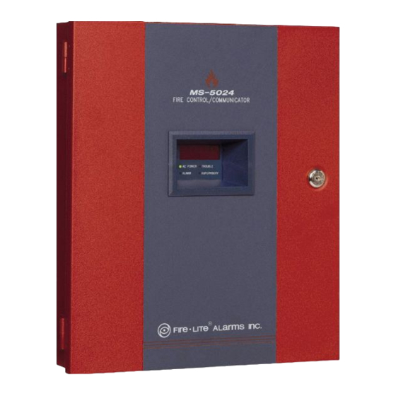
The MS-5024/MS-5024E
Fire Control
Communicator
Installation, Programming, Operation
and Maintenance Manual
12 Clintonville Road, Northford, CT 06472
firealarmresources.com
Document # 50066
Document # 50066
Document # 50066
Document # 50066
Document # 50066
D
5/2/97
5/2/97
5/2/97
5/2/97
5/2/97
Rev:
P/N 50066:D
ECN 97-173
© 1997 Fire•Lite Alarms, Inc.
Advertisement
Table of Contents

Related Manuals for Fire-Lite Alarms MS-5024


Summary of Contents for Fire-Lite Alarms MS-5024
- Page 1 The MS-5024/MS-5024E Fire Control Communicator Installation, Programming, Operation and Maintenance Manual Document # 50066 Document # 50066 Document # 50066 Document # 50066 Document # 50066 5/2/97 5/2/97 5/2/97 5/2/97 5/2/97 Rev: 12 Clintonville Road, Northford, CT 06472 P/N 50066:D ECN 97-173 ©...
- Page 2 Technical Manuals Online! - http://www.tech-man.com firealarmresources.com...
-
Page 3: Table Of Contents
NFPA Standards, UL Documents Product Description Product Features Figure 1-1: Optional DP-5024 Figure 1-2: MS-5024 Panel Controls and Indicators Circuits Digital Communicator Components Optional Devices Specifications Telephone Requirements and Warnings 1.8.1 Telephone Circuitry 1.8.2 Digital Communicator 1.8.3 Telephone Company Rights and Warnings 1.8.4 For Canadian Applications... - Page 4 Operating Instructions Switches Displays Figure 4-1: Phone Connectors & LEDs Operation 4.3.1 Alarm Response 4.3.2 Alarm Restoral 4.3.3 System Supervisory Condition Response 4.3.4 System Supervisory Restoral Response 4.3.5 Trouble Condition Response 4.3.6 Trouble Condition Restoral 4.3.7 OFF Normal Reporting 4.3.8 Zone Disable/Enable 4.3.9 Fire Drill Central Station Communications Table 4-1: Format Selection Address (16 + 42)
-
Page 5: Nfpa Standards, Ul Documents
This control panel has been designed to comply with standards set forth by the following regulatory agencies: • Underwriters Laboratories Standard UL 864 • NFPA 72-1993 National Fire Alarm Code for Local, Remote Station and Central Station Fire Alarm Systems •... - Page 6 Secondary Transformer Connector Note: When dressing wires, maintain a minimum of a 1/4" distance between conductors to power limited and non-power limited circuits. 50066 Rev D 5/2/97 P/N 50066:D Technical Manuals Online! - http://www.tech-man.com firealarmresources.com...
-
Page 7: Product Description
1.0 Product Description The MS-5024 is a combination control panel and digital communicator all on one circuit board. It is a five-zone panel which uses conventional input devices. The panel accepts waterflow devices, two-wire smoke detectors, four-wire smoke detectors, pull stations and other normally open contact devices. Outputs include two Notification Appliance Circuits, and two programmable relays. - Page 8 Four Character 7-Segment LED Display Piezo 85dB Primary & Secondary Phone Lines Keypad Holds up to 7AH Batteries Up to 60 Hrs. of Standby Figure 1-2: MS-5024 Panel 50066 Rev D 5/2/97 P/N 50066:D Technical Manuals Online! - http://www.tech-man.com firealarmresources.com...
-
Page 9: Controls And Indicators
Controls and Front Panel Switches RESET Digits 0-9 Indicators SILENCE MODE Up Arrow Down Arrow 1st EVENT ENTER/STOREF Displays • Alarm - red LED • Trouble - yellow LED • Supervisory - yellow LED • AC Power - green LED •... -
Page 10: Digital Communicator
Digital Two modular phone jacks allow easy connection to telephone lines. Modular jacks are labeled PH1 and PH2 for the Primary and Secondary phone lines. Telephone line Communicator active red LEDs are provided as well as a green 'Kissoff' LED. The integral digital communicator provides the following functions: •... -
Page 11: Optional Devices
1.6 Optional Devices ADM-24 The ADM-24 Annunciator Driver Module supports the RZA-5F Remote Annunciator module. Annunciator wiring is supervised for open circuits by this module. The Annunciator Driver Module mounts to connector J3 in the upper right corner of the main board. See Figure 1-2 and 2-10. Remote Annunciator The RZA-5F Remote Annunciator mounts on a standard single-gang box, and provides LED indication of the following:... -
Page 12: Specifications
Battery (Supervised ) - lead acid only - J1 Maximum Charging Circuit: Normal Flat Charge—27.6V @ .8 amp. Maximum Charger Capacity: 17 Amp Hour battery. (MS-5024 cabinet holds max. 7 Amp Hour battery. Larger batteries require Fire-Lite #BB-17F or other UL listed battery cabinet). -
Page 13: Telephone Requirements And Warnings
: Manufacturer : Fire·Lite Alarms, Inc. 12 Clintonville Rd. Northford, CT 06472 Product Model Number: MS-5024 FCC Registration Number: 1W6USA-20004-AL-E Ringer Equivalence 1.3B 1.8.3 Telephone Company Rights and Warnings: The telephone company under certain circumstances may temporarily discontinue services and/or make changes in its facilities, services, equipment or procedures which may affect the operation of this control panel. -
Page 14: For Canadian Applications
The control panel must be connected to the public switched telephone network upstream of any private telephone system at the protected premises. An FCC compliant telephone cord must be used with this equipment. This equipment is designed to be connected to the telephone network or premises wiring using a compatible RJ31X male modular plug which is Part 68 compliant. -
Page 15: Installation
2.0 Installation General Mounting Options The cabinet may be either semi-flush or surface mounted. The door is removable during the installation period by opening and lifting off the hinges. The cabinet mounts using two key slots and two additional 0.250" diameter holes located in the backbox. - Page 16 Right Side Bottom Draw wires through the respective knockout locations. Figure 2-1: Cabinet Dimensions & Knockout Locations 50066 Rev D 5/2/97 P/N 50066:D Technical Manuals Online! - http://www.tech-man.com firealarmresources.com...
- Page 17 Notes: 1) Mount the MS-5024 cabinet to wall. 2) Remove appropriate knockouts from FACP cabinet and BB-17F. 3) Position BB-17F near MS-5024 cabinet and connect with conduit making sure there is at least 1/2" of clearance between the two cabinets.
-
Page 18: Operating Power
0.6 amps. Run a pair of wires (with ground conductor) from the protected premises main breaker box to the orange and black primary leads of the MS-5024 transformer. As per the National Electric Code, use 14 AWG (1.6 mm O.D.) or heavier gauge wire with 600V insulation. -
Page 19: Input Circuits
DC Power Output Connections All DC power outputs are power-limited *Non-resettable Power (300 mA) *4-Wire Smoke Detector Power (300 mA) 24 VDC filtered, non-resettable 24 VDC filtered, resettable power for 4-wire power can be obtained from TB4 smoke detectors can be obtained from TB4 Terminals 1 (+) and 2 (-). -
Page 20: Output Circuits
See Figure 2-9. Notification Appliance Circuits (Full-wave Rectified) The MS-5024 provides two Notification Appliance Circuits (Style Y), each circuit capable of 1.5 amps of current. Total current drawn from these as well as other DC power outputs cannot exceed 3.6 amps. Circuits are supervised and power-limited. - Page 21 Style Y Notification Appliance Circuit (Supervised and Polarized Bell power-limited). 4.7K Ω , 1/2- Watt Part# 71252 UL listed. Polarized Horn Polarized Horn Note: Notification Appliance Circuit polarity shown in Dummy Load all alarm state. unused Circuits (Part# 71245) Note: Both Notification Appliance Circuits may be programmed as follows: •...
-
Page 22: Ul Power-Limited Wiring Requirements
Furthermore, all power-limited circuit wiring and nonpower-limited circuit wiring must enter and exit the cabinet through different knockouts and/or conduits. A typical wiring diagram for the MS-5024 is shown below. Power-limited Circuits Nonpower-limited Circuits AC Power... -
Page 23: Digital Communicator
Digital Two independent telephone lines can be connected to the control panel. Telephone line control/command is made possible via double line seizure as well as usage of an Communicator RJ31X style interconnection. The control panel's digital communicator is built into the main board. Connection and wiring of two phone lines is required as shown below. -
Page 24: Optional Boards
Optional ADM-24 Annunciator Driver Module The Annunciator Driver Module supports the RZA-5F Remote Annunciator. Annunciator Boards wiring is supervised for open conditions by this module. The Annunciator Driver Module mounts to J3 in the upper right corner of the main board. ADM-24 Standoff Connector located on... - Page 25 +24V Note: Make wiring connections with system power off. Maximum wire impedance is 100 ADM-24 ohms per wiring connection. RZA-5F Figure 2-12: Wiring the RZA-5F/ADM-24 screw # 6-32 x 1.00" LG Figure 2-13: Installing the Annunciator (Single Gang Box) 50066 Rev D 5/2/97 P/N 50066:D Technical Manuals Online! - http://www.tech-man.com firealarmresources.com...
- Page 26 Insert two supplied standoffs into NACA- 2F circuit board, remove protective paper from self adhesive base of standoff, install circuit board into TB5 of MS-5024 and press to adhere standoffs to cabinet. Dummy load any unused circuits with 4.7K ELR P/N: 71245 across B+ and B-...
-
Page 27: Programming Instructions
3.0 Programming Instructions Programming Mode This section describes programming the panel from the onboard keypad. Programming of the control panel is possible at any time except when an alarm condition is present or during a fire drill. The control panel has been designed for many different types of applications. After examining your specific application, review the programming options and choose the entries best suited for your system. -
Page 28: Switch Functions
Note: Location 56 is factory defaulted to = 0, Control Panel only. This keeps the communicator off until location 56 is changed to: 1= slave communicator or 2 = panel/communicator. Once location 56 is set to 1 or 2 and a valid phone number is entered, entry into the program mode will cause transmission of the "System off Normal"... - Page 29 Valid entries for both the primary and secondary phone numbers are 0 - F with the numeric digits as dialed numbers and hex digits representing the following functions: A= * on a Touchtone phone keypad B= # on a Touchtone phone keypad C= look for secondary dial tone for up to 2 seconds (then, dial anyway) D= 3-second pause E= 5-second pause...
- Page 30 3+1, 4+1 Express, 4+1 Standard and Expanded, 4+2 Expanded Formats If '0, 2, 3, 4, 5, 6, 7, 8, 9, B or D' are entered for address 16, the following data is automatically programmed for the Primary Central Station phone number event codes.
- Page 31 4+2 Standard and 4+2 Express Format If '1, A or C' are entered for address 16, the following data is automatically programmed for the Primary Central Station phone number event codes. Enter '00' for the setting to disable the report. Address Description Settings...
- Page 32 Primary Central Station Number Account Code (17-20) Four locations at addresses 17-20 default to all '0's. Valid entries are (0-9 and A-F). The number of digits entered must match the format selection. If programming '2, 3, 4, or 5' into address 16, enter 3 digits.
- Page 33 3+1, 4+1 Express, 4+1 Standard and Expanded, and 4+2 Expanded Formats If '0, 2, 3, 4, 5, 6, 7, 8, 9, B or D' are entered for address 42, the following is automat- ically programmed for the Secondary Central Station phone number event codes. Enter '0' for the setting to disable the report.
- Page 34 4+2 Standard and 4+2 Express Formats f '1, A or C' are entered for address 42, the following is automatically programmed for the Secondary Central Station phone number event codes. Enter '00' for the setting to disable the report. Address Description Setting 198 - 199...
- Page 35 Secondary Central Station Number Account Code (43-46) is programmed in addresses 43 - 46 in the same manner as the primary phone number Account Code. Default entries are all '0s'. Secondary Central Station Number 24-Hour Test Time (47-50) is programmed in addresses 47-50 in the same manner as the primary number 24-Hour Test Time.
- Page 36 Programmable Relay 1 (53) Programmable Relay 1 may be programmed to activate on alarm, trouble, supervisory, communications failure, or any combination of the four conditions. The default (factory setting) for this address is '1' for activation on alarm only. Valid entries for address 53 are 0 through F as listed below: 0 = Disable 1 = Alarm...
- Page 37 Zone 1 Function Selection (57) Factory default for zone 1 is '0', 2-wire smoke detector. Enter 1 for pull station, 2 for Normally Open contact device, 3 for Supervisory or 4 for Supervisory, auto resettable. Zone 2 Function Selection (58) Factory default for zone 2 is '0', 2-wire smoke detector.
- Page 38 Alarm Presignal Delay Timer (66-68) The Alarm Presignal timer is factory set to 120 seconds (2 minutes), address 66=1, 67=2 and 68=0. The timer may be programmed from 0 to 179 seconds. Location 65 must be set to '1'. Notification Appliance Circuit #1 Enable (69) Notification Appliance Circuit #1 may be programmed as 0=silenceable, 1=non- silenceable or 2=disabled.
- Page 39 Note that the software for the MS-5024 operates the internal clock based upon 60 Hz. The software for the MS-5024E operates the internal clock based upon 50Hz.
- Page 40 4.0 Operating Instructions Normal Mode The MS-5024 has five Modes of operation; Normal, Program, Walk Test, Troubleshoot, and History. Upon initial power up, the system will be in Normal Mode. This section discusses operation of the control panel in the Normal Mode.
- Page 41 SILENCE If the Silence Switch is pressed: • The silenceable Notification Appliance Circuits will be turned OFF. • The silence LED will be turned ON. • The piezo sounder will be shut OFF. • 'System Silenced' message will be stored in the History file. Upon the occurrence of a subsequent event (alarm or trouble), System Silence is overridden and the control panel will respond to the new event.
- Page 42 Individual LEDs are provided for: System Alarm—A red LED that turns on steady when an alarm condition is detected and blinks during alarm Positive Alarm Sequence period. System Trouble—This yellow LED blinks to indicate that a fault or abnormal condition exists and that the fire alarm system may be inoperative. It turns on steady when the silence switch is pressed.
- Page 43 Operation Normal mode is the standard mode of operation. In this mode, the panel continuously monitors system status. When no alarm or trouble conditions exist, the display will be blank and all LEDs will be off (except the AC Power LED). The Notification Appliance Circuits will be off all relays are normal and the onboard piezo sounder will be off.
- Page 44 4.3.2 Alarm Restoral The control panel only returns to normal after all alarms have been cleared and the Reset switch has been pressed (pull stations reset, smoke detectors reset and no smoke is present, waterflow has stopped). The control panel will perform the following upon restoral of all active alarms: •...
- Page 45 Possible trouble messages that may appear on the display are as follows: _AC_ AC Loss (shown only when requested) d__1 Zone 1 disabled F__E Ground fault d__2 Zone 2 disabled Lo_b Low battery d__3 Zone 3 disabled no_b No battery d__4 Zone 4 disabled no_1...
- Page 46 4.3.9 Fire Drill The DRILL (manual evacuate) feature turns on both Notification Appliance Circuits (if programmed as enabled) and turns off the silence LED. To perform a fire drill, press the MODE key followed by the code 3745 then enter. The display will read dril.
- Page 47 Communications Failure. Note that as an option, all reports may also be sent to the Secondary Central Station phone number. The MS-5024 meets NFPA 72-1993 National Fire Code reporting requirements for: (a) the type of signal (b) condition and (c) location of the reporting premises. The general priority reporting structure is: 1.
- Page 48 Where: SSS 0r SSSS = Subscriber ID = Alarm (1st digit) = Alarm (2nd digit) = Zone Number = Alarm Restore (1st digit) = Alarm Restore (2nd digit) = Zone Trouble (1st digit) = Zone Trouble (2nd digit) = Zone Trouble Restore (1st digit) RTZ2 = Zone Trouble Restore (2nd digit) = System Trouble (1st digit)
- Page 49 4.4.1 Transmittal Priorities The integral communicator transmits highest priority events first. Events in terms of priority are listed below in descending order: 1: Alarms (Highest Priority Level) Pull Stations Waterflow Smoke Detector Other Alarm Types 2: Supervisory Zone 3: System Troubles Zone Disabled Fire Drill AC Fail (After Delay)
- Page 50 The chart below shows UL listed receivers compatible with the MS-5024: Format # (Addresses 16 & 42) 4+1 Ademco Express 4+2 Ademco Express (5,6) 3+1/Standard/1800/2300 3+1/Expanded/1800/2300 3+1/Standard/1900/1400 3+1/Expanded/1900/1400 4+1/Standard/1800/2300 4+1/Expanded/1800/2300 4+1/Standard/1900/1400 4+1/Expanded/1900/1400 4+2/Standard/1800/2300 4+2/Expanded/1800/2300 4+2/Standard/1900/1400 4+2/Expanded/1900/1400 Not Used Not Used (1) With 685-8 Line Card with Rev 4.4d software.
- Page 51 5.0 Servicing 5.1 Walk Test Mode The MS-5024 provides the capability to perform a one-man walk test of the system without triggering the communicator, or the alarm relay (if programmed). Walk Test allows for testing of the five zones (initiating circuits). The first initiating device activated on a zone will cause the Notification Appliance Circuits to turn on for four seconds.
- Page 52 To return the control panel to normal mode, press the mode key, the numbers 6676 and the [ENTER/STORE] key. Any delay between key entries greater than 10 seconds causes the control panel to remain in Walk Test Mode. The control panel will automatically revert back to Normal Mode if no system activity has occurred for 60 minutes.
- Page 53 Shown below is the list of messages as they will appear on the display: DISPLAY EVENT d__1 Zone 1 disabled A__1 Zone 1 Alarm d__2 Zone 2 disabled A__2 Zone 2 Alarm d__3 Zone 3 disabled A__3 Zone 3 Alarm d__4 Zone 4 disabled A__4...
- Page 54 Listed below is the AC line voltage range. The AC ON indicator will turn off when the AC line voltage drops below the Low Line threshold, and the trouble LED will turn on. AC Line Voltage: Low Line Normal High Line MS-5024 102VAC 115VAC 132VAC MS-5024E 204VAC...
- Page 55 NAC 1 & 2 NAC voltage readings are nominally -2.32 volts when an EOL resistor of correct value is in place. A reading of 0.00 volts appears for shorts, -4.50 volts for opens. Intermediate readings are also available. Telephone Lines Pressing C for touchtone dialing or D for rotary dialing, followed by [ENTER/ STORE] causes seizure of the Primary phone line which in turn lights the red LED signifying Primary phone line active.
- Page 56 6.0 Slave Communicator Configuration The MS-5024 may be used as a slave communicator to a host or Master fire alarm control panel (FACP). All wiring between the Master and the slave communicator is supervised. End of line resistors, 4.7K, should be connected.
- Page 57 Relays in Master FACP activate various input circuits on the slave communicator. Messages (event codes) programmed for a particular input circuit (channel) will be transmitted to the central station upon relay activation. Figure 6-1: Slave Communicator Connections 50066 Rev D 5/2/97 P/N 50066:D Technical Manuals Online! - http://www.tech-man.com firealarmresources.com...
- Page 58 Appendix A: Battery Calculations Use the Total Standby and Alarm Load Currents calculated in Tables A-2A and A-2B for the following battery calculation. Standby Load Required Standby Time in Current (Amps) Hours (24 or 60 Hours) __________ Alarm Load Required Alarm Time in Hours Current (Amps) (i.e.
- Page 59 The Main Power Supply The MS-5024 provides regulated power for operating the fire alarm control panel, operating external devices, and operating the standby battery. The power for operating external devices is limited. Use Table A-2A (standby or non- alarm) and Table A-2B (alarm) to determine if external loading is within the capabilities of the power supply.
- Page 60 @24 VDC Table A-2B: Regulated Load in Alarm Current Total Current Device Type # of Devices (Amps) (Amps) Main Circuit Board 0.255 0.255 ADM-24 (1 max.) 0.006 RZA-5F (1 max.) 0.046 CAC-5F (1 max.) NACA-2F (1 max.) 4-Wire Smoke _____ Detector Power Supervision 0.025...
- Page 61 Appendix B: Programming Reference Sheet --- To enter Programming, press Mode: 7 7 6 4, Enter Addresses 00 to 15 store the Primary Central Station Phone Number. Enter 'F' to represent the end of the number. Primary Central Station Comm Format: Enter 0 - D. Primary Central Station Account Code: Valid keys are 0-F.
- Page 62 Zone 2 Function Select. Enter '0' for 2-wire smoke detectors; '1' for pull station; '2' for normally open contact devices; '3' for supervisory devices; '4' for supervisory devices (auto resettable). Zone 3 Function Select. Enter '0' for 2-wire smoke detectors; '1' for pull station; '2' for normally open contact devices;...
- Page 63 Programming Reference Sheet 50066 Rev D 5/2/97 P/N 50066:D Technical Manuals Online! - http://www.tech-man.com firealarmresources.com...
- Page 64 Programming Reference Sheet Factory Default Settings --- To enter Programming, press Mode: 7 7 6 4, Enter Addresses 00 to 15 store the Primary Central Station Phone Number. Enter 'F' to represent the end of the number. Primary Central Station Comm Format: (4+2 Standard 1800/2300). Primary Central Station Account Code.
- Page 65 Coding NAC #1. '0' for steady, no coding. Notification Appliance Circuit #2 Selection: '0' for enabled (silenceable). Silence Inhibit NAC #2. '0' for no silence inhibit. Auto Silence NAC #2. '0' for no auto silence. Coding NAC #2. '0' for steady, no coding. Trouble Reminder.
- Page 66 Programming Reference Sheet Factory Default 50066 Rev D 5/2/97 P/N 50066:D Technical Manuals Online! - http://www.tech-man.com firealarmresources.com...
- Page 67 Connecting external system accessories to the MS-5024 main circuits must be carefully considered to ensure proper operation. It is important to use the correct type of wire, wire gauge and wire run length per each MS-5024 circuit. Reference the chart below to specify wire requirements and limitations for each MS-5024.
- Page 68 Appendix D: Operation and Function Modes OPERATION MODES . f f . f f e l i . e l . f f i t c e l i l l a FUNCTION MODES o l l n i l .
- Page 69 Notes 50066 Rev D 5/2/97 P/N 50066:D Technical Manuals Online! - http://www.tech-man.com firealarmresources.com...
- Page 70 Notes 50066 Rev D 5/2/97 P/N 50066:D Technical Manuals Online! - http://www.tech-man.com firealarmresources.com...
- Page 71 50066 Rev D 5/2/97 P/N 50066:D Technical Manuals Online! - http://www.tech-man.com firealarmresources.com...
- Page 72 Limited Warranty Fire-Lite ® warrants its products to be free from defects in materials and workmanship for eighteen (18) months from the date of manufacture, under normal use and service. Products are date stamped at time of manufacture. The sole and exclusive obligation ®...
Need help?
Do you have a question about the MS-5024 and is the answer not in the manual?
Questions and answers