Table of Contents
Advertisement
Instructions
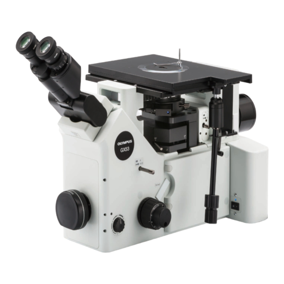
GX53
Inverted system metallurgical microscope
Notes
This instruction manual is for the Olympus microscope.
To ensure safety, obtain optimum performance and to familiarize yourself fully with the use of this
product, we recommend that you study this manual thoroughly before operating this product, and
always keep this manual at hand when operating this product.
Optical Microscope and Accessory
Retain this instruction manual in an easily accessible place near the work desk for future reference.
For details of products included in the configuration of this microscope, see page 10.
Advertisement
Table of Contents

Related Manuals for Olympus GX53


Summary of Contents for Olympus GX53
- Page 1 Inverted system metallurgical microscope Notes This instruction manual is for the Olympus microscope. To ensure safety, obtain optimum performance and to familiarize yourself fully with the use of this product, we recommend that you study this manual thoroughly before operating this product, and always keep this manual at hand when operating this product.
- Page 2 Refer to your local Olympus distributor in EU for return and/or collection systems available in your country. NOTE: This product has been tested and found to comply with the limits for a Class A digital device, pursuant to Part 15 of the FCC Rules.
-
Page 3: Table Of Contents
GX53 Contents Introduction ............................... 1 Safety precautions ............................2 1 Nomenclature of units ........................9 2 List of combinable units .........................10 3 Basic operations of the microscope (Reflected light brightfield/darkfield observations) ..........14 3-1 Reflected light brightfield/darkfield observation procedures ........14 3-2 Turning ON the main switch........................16 3-3 Selecting the observation method ....................17... - Page 4 3-11 Adjusting the field diaphragm (FS) ....................27 3-12 Using the filter sliders ..........................28 3-13 Observing the image using the mercury burner ............... 29 4 Various observation methods ....................30 4-1 Reflected light differential interference contrast (DIC) observation ..... 30 4-2 Reflected light simple polarization observation ..............
- Page 5 GX53 7 Troubleshooting ............................ 56 8 Specifications ............................60 9 Optical performance list <<UIS2 series>> ................62 10 Assembly ..............................65 10-1 Assembly diagram ............................65 10-2 Assembly procedures ..........................66 Attaching the light source ..............................66 Attaching the objective .................................68 Attaching the revolving nosepiece ..........................68...
-
Page 7: Introduction
UIS2 optical system series. Using inappropriate units restricts the performance. (There are other units usable with the UIS series. Contact Olympus or refer to the latest catalogs.) Configuration of instruction manuals Read all instruction manuals provided with the units you purchased. -
Page 8: Safety Precautions
Safety precautions If the product is used in a manner not specified by this manual, the safety of the user may be imperiled. In addition, the product may also be damaged. Read this instruction manual carefully and always use this product according to this instruction manual. The following symbols are used in this instruction manual. - Page 9 GX53 CAUTION - Electric safety - Always use the AC adapter and the power cord specified by Olympus. If the proper AC adapter, the power cord and cables are not used, the electric safety and the EMC (Electro-Magnetic Compatibility) performance of the product cannot be assured. If no power cord is provided, please select the proper power cord by referring to the section “Proper selection of the power cord”...
- Page 10 82. If you find the unexpected phenomena, e.g. smoke, etc. during operation, turn OFF the power immediately and contact Olympus. CAUTION - Liquid Light Guide - Do not use the liquid light guide that is not conformed to this product.
- Page 11 CAUTION - Prevention of fire - Do not repair, disassemble or remodel. Never repair, disassemble or remodel this product. Otherwise, fire may result. The repair work must be carried out only by those authorized by Olympus. If you need repairs, contact Olympus for assistance.
- Page 12 (Seesaw type is the type of switch where ON or OFF is selected by pressing it to ON or OFF side.) Indicates that the seesaw type main switch is OFF. When caution labels are dirty or peeled off, contact Olympus for replacement or inquiries. Label position and instruction The labels are attached to the portions which require special cautions during use and operation.
- Page 13 Be sure to contact Olympus for assistance. Handling Precautions · This product is a precision instrument. Handle it with care and avoid subjecting it to a sudden or severe NOTE impact.
- Page 14 4. Before disposing of this product, be sure to check the regulations and rules of your local government and follow them. Contact Olympus for any questions. 5. If the hour counter of the power supply (U-RFL-T) shows 300 hours, set the main switch to (OFF) for safety purpose, wait 10 minutes or more and replace the lamp.
-
Page 15: Nomenclature Of Units
GX53 Nomenclature of units The diagram shown in this section shows the major units only. For units combinable to this product, see “2 List of combinable units". For units marked “ * ”, refer to the instruction manuals provided separately. -
Page 16: List Of Combinable Units
List of combinable units : Combination available (including units with restrictions) : Combination prohibited : Unnecessary for observation Reflected light Transmitted light Observation method Brightfield/ Differential Simple Simple Brightfield Darkfield darkfield interference Brightfield Unit polarization polarization simultaneously contrast Microscope frame GX53F Observation tube U-BI90... - Page 17 GX53 : Combination available (including units with restrictions) : Combination prohibited : Unnecessary for observation Reflected light Transmitted light Observation method Brightfield/ Differential Simple Simple Brightfield Darkfield darkfield interference Brightfield Unit polarization polarization simultaneously contrast Revolving nosepiece U-P4RE U-P5BDRE U-P6RE...
- Page 18 : Combination available (including units with restrictions) : Combination prohibited : Unnecessary for observation Reflected light Transmitted light Observation method Brightfield/ Differential Simple Simple Brightfield Darkfield darkfield interference Brightfield Unit polarization polarization simultaneously contrast MIX slider for reflected U-MIXR light observation U-MIXRCBL Polarizing element GX-PO...
- Page 19 GX53 : Combination available (including units with restrictions) : Combination prohibited : Unnecessary for observation Reflected light Transmitted light Observation method Brightfield/ Differential Simple Simple Brightfield Darkfield darkfield interference Brightfield Unit polarization polarization simultaneously contrast Controller DP2-SAL Hand switch BX3M-HS...
-
Page 20: Basic Operations Of The Microscope (Reflected Light Brightfield/Darkfield Observations)
Basic operations of the microscope (Reflected light brightfield/darkfield observations) This section describes the operating procedures of the reflected light brightfield/darkfield observations which are the basis of observation methods. The polarization observation and the differential interference contrast observation, etc. are described in “4 Various observation methods" on page 30. 3-1 Reflected light brightfield/darkfield observation procedures Operation part Page... - Page 21 GX53 Diopter adjustment Field diaphragm lever (P.27) ring (P.23) Light path selection knob on trinocular tube (P.18) Aperture diaphragm lever (P.26) Filter slider insertion slot Filter slider insertion slot Filter slider insertion slot (P.28) (P.28) Interpupillary distance adjustment scale (P.23) BF/DF selection lever (P.17)
-
Page 22: Turning On The Main Switch
3-2 Turning ON the main switch When using the reflected LED light source (BX3M-LEDR) Set the main switch a to (ON). When using the light source other than the reflected LED light source (BX3M-LEDR) Set the main switch of each unit to (ON). Combinable units Unit to set to ON Main switch of the power supply for... -
Page 23: Selecting The Observation Method
GX53 3-3 Selecting the observation method Engage the mirror according to the observation method to set the observation light path. BF: Reflected light brightfield observation (ND filter can be built-in.) This position is also used for the reflected light brightfield/... -
Page 24: Selecting Between The Eyepiece Light Path And The Camera Light Path
3-4 Selecting between the eyepiece light path and the camera light path Slide the eyepiece/camera light path selection knob a on the microscope frame to select the required light path. Knob on frame a Eyepiece light path Camera light path 100% Selecting the light path when using the side port unit GX-SPU Knob position... -
Page 25: Placing A Sample
GX53 3-5 Placing a sample Placing a sample Select the stage center plate a according to the sample size and place it on the hole at the center of the stage. Place the sample on the stage center plate gently with the sample surface to be observed facing down. -
Page 26: Selecting The Objective
3-6 Selecting the objective Be careful, when selecting the objective, it may collide NOTE with the stage depending on the focusing position. Rotate the revolving nosepiece a to select the objective so that the desired objective comes to the position under the sample. For procedures to attach and remove the objective, see “6-2 Replacing the objective"... -
Page 27: Focusing
GX53 3-7 Focusing Focusing Rotate the coarse focusing knob a in arrow direction to move the objective to the sample as close as possible. While observing the sample through the eyepieces, slowly rotate the coarse focusing knob a in the direction opposite to the arrow direction to lower the stage. -
Page 28: Adjusting The Brightness
3-8 Adjusting the brightness When the reflected LED light source is combined Rotate the brightness control knob a of the microscope frame clockwise to increase the brightness of the illumination. When the halogen lamp housing is combined Rotate the brightness control knob a of the power supply for halogen bulb (TH4-100/TH4-200) to MAX (high voltage side) to increase the brightness of the illumination. -
Page 29: Adjusting The Observation Tube
GX53 3-9 Adjusting the observation tube Adjusting the interpupillary distance The adjustment of the interpupillary distance is to adjust the distance between two eyepieces to fit to the distance between your two eyes. By doing so, you can see the single microscope image so that the fatigue of your eyes during observation can be reduced. - Page 30 When the eyepiece is equipped with the eyepiece micrometer While looking through the eyepiece equipped with the eyepiece micrometer, rotate the diopter adjustment ring a to adjust so that the scales or lines (A in the picture on the left) of the eyepiece micrometer in the field of view are clearly visible.
-
Page 31: Using The Eye Shades
GX53 Using the eye shades When wearing eyeglasses Use the eye shades in the folded-down position. When not wearing eyeglasses Raising the folded-down eyeshades in the arrow direction prevents the unnecessary light from entering between eyepieces and eyes. Adjusting the tilting (U-TBI90 only) You can adjust the observation tube to the easy-to-see height and angle so that you can observe with a comfortable posture. -
Page 32: Adjusting The Aperture Diaphragm (As)
3-10 Adjusting the aperture diaphragm (AS) Slide the BF/DF selection lever to set to the BF side. Rotate the revolving nosepiece to engage the 10X objective in the light path and bring the sample into focus approximately. If you remove the eyepieces and look into the observation tube, you can see the aperture diaphragm image. -
Page 33: Adjusting The Field Diaphragm (Fs)
GX53 3-11 Adjusting the field diaphragm (FS) Slide the BF/DF selection lever to set to the BF side. Rotate the revolving nosepiece to engage the 10X objective in the light path and place the sample on the stage to bring it into focus approximately. -
Page 34: Using The Filter Sliders
3-12 Using the filter sliders Engage the filter mounted on the filter sliders and GX-FSL a in the light path from the left side. The filter slider can also be inserted from the right side, but the filter slider does not stop at the first click position. ·... -
Page 35: Observing The Image Using The Mercury Burner
GX53 3-13 Observing the image using the mercury burner Turning ON the power supply for mercury burner Set the main switch a to (ON). For details, refer to the instruction manual provided with the unit. Adjusting the brightness Slide the BF/DF selection lever to set to the BF side. -
Page 36: Various Observation Methods
Various observation methods 4-1 Reflected light differential interference contrast (DIC) observation For the DIC (Differential Interference Contrast) observation, following units are required. · Analyzer: GX-AN360 or GX-AN · Polarizer: GX-PO or GX-POTP ( PO surface) · DIC slider: U-DICR (standard), U-DICRH* or U-DICRHC * When using the DIC slider U-DICRH to perform the sensitive color observation, combine the polarizer GX-POTP. -
Page 37: Reflected Light Simple Polarization Observation
GX53 4-2 Reflected light simple polarization observation When performing the sensitive color observation, combine the polarizer (GX-POTP). NOTE Operation part Page Main switch P.16 Set the main switch to (ON). BF/DF selection lever P.17 Select the brightfield (BF) observation. Eyepiece/camera light path selection P.18... -
Page 38: Reflected Light Brightfield/Darkfield Simultaneous Observation
4-3 Reflected light brightfield/darkfield simultaneous observation Operation part Page Main switch P.16 Set the main switch to (ON). Select the brightfield (BF) observation. BF/DF selection lever P.17 Remove the analyzer, polarizer or filter sliders from the light path. Eyepiece/camera light path selection P.18 knob Select the observation light path. -
Page 39: Transmitted Light Brightfield Observation
GX53 4-4 Transmitted light brightfield observation For the transmitted light brightfield observation, following units are required. · Transmitted illuminator column: IX2-ILL100 [LED] [Halogen bulb] · LED light source: BX3M-LEDT · Halogen lamp housing: U-LH100L-3 (Extension cord U-RMT is required.) · Power supply: BX3M-PSLED ·... -
Page 40: Transmitted Light Simple Polarization Observation
4-5 Transmitted light simple polarization observation Operation part Page Main switch P.41 Set the main switch to (ON). BF/DF selection lever P.17 Select the brightfield (BF) observation. Eyepiece/camera light path selection P.18 knob Select the observation light path. Light path selection knob on trinocular tube or Observation/SP selection knob on the side port Stage plate... -
Page 41: Using The Analyzer/Polarizer For Reflected Light Observation
GX53 4-6 Using the analyzer/polarizer for reflected light observation If the DIC slider is engaged in the light path, remove it from the light path. For details, see “Inserting the DIC slider" on page 36. Engage the 10X objective or 20X objective in the light path and bring the sample into focus approximately. -
Page 42: Using The Dic Slider
4-7 Using the DIC slider Inserting the DIC slider Loosen the mounting knob a at the rear right of the revolving nosepiece and pull out the dummy slider b . Insert the DIC slider c for reflected light observation in the slider insertion slot of the revolving nosepiece with the display surface facing down, and stop inserting at the first level (when the clicking sound is heard at first). -
Page 43: Adjusting The Prism Of The Dic Slider
GX53 Adjusting the prism of the DIC slider Rotate the prism movement knob a of the DIC slider to select the interference color with the highest contrast according to the sample. U-DICR, U-DICRHC The interference color of the background changes continuously from the gray sensitive color to the magenta sensitive color (from -100 to 600 nm). -
Page 44: Using The Mix Slider For Reflected Light Observation
4-8 Using the MIX slider for reflected light observation Inserting the MIX slider for reflected light observation Loosen the mounting knob a at the rear right of the revolving nosepiece and pull out the dummy slider b . Insert the MIX slider for reflected light observation (U-MIXR) c into the slider insertion slot of the revolving nosepiece so that the connector d comes to the left side, and push it in the second level (position where the clicking sound is heard). -
Page 45: Turning On The Illumination Of The Mix Slider For Reflected Light Observation
GX53 Turning ON the illumination of the MIX slider for reflected light observation If you press the ON/OFF button a of the hand switch (BX3M-HS) to set it to ON, the illumination of the MIX slider for reflected light observation (U-MIXR) turns ON. -
Page 46: Selecting The Illumination Pattern
Selecting the illumination pattern Press the MODE button a of the hand switch (BX3M-HS) to select the illumination pattern. The indicator b turns ON according to the illumination pattern. Operation Function Changes the illumination Short press pattern. Long press The illumination pattern rotates (Short press while the illumination clockwise automatically. -
Page 47: Adjusting The Units For Transmitted Light Observation
GX53 4-9 Adjusting the units for transmitted light observation Centering the condenser Set the main switch ( a or b ) of the reflected LED light source (BX3M- PSLED) or the power supply for halogen bulb (TH44-100/TH4-200) to (ON), and rotate the brightness control knob to set the appropriate brightness. - Page 48 Using the aperture diaphragm (AS) for transmitted light observation Rotate the aperture diaphragm ring a to set the index to 70% of the numerical aperture of the objective. While looking at the observed image, rotate the aperture diaphragm ring a to fine-adjust it to obtain the desired image. To check the outer diameter of the aperture diaphragm, remove the eyepieces and look into the eyepiece sleeves to view the aperture diaphragm image with respect to that of the...
-
Page 49: Tilting Of The Illumination Column
GX53 Tilting of the illumination column When replacing large samples, it is recommended to tilt the illumination column to make a larger working space. Even if the illumination column is tilted, the sample surface is illuminated, which is convenient for checking samples roughly or positioning the samples when placing them. -
Page 50: Image Acquisition
Image acquisition Attaching the camera adapter and the microscope digital camera to the trinocular tube allows you to acquire the observed image. The image acquisition range is determined by the size of the image sensor used in the camera and the magnification of the camera adapter. -
Page 51: Replacement Of Optical Parts
GX53 Replacement of optical parts 6-1 Replacing the eyepiece Removing the eyepiece Pull out the eyepiece a from the eyepiece sleeve b . Attaching the eyepiece micrometer You can use the eyepiece micrometer to check the size of the observed image or the center position of the observation field of view, etc. - Page 52 Attaching the eyepiece Insert the eyepiece a into the eyepiece sleeve b until it touches the end. · As the binocular tube does not have a positioning groove, NOTE an eyepiece equipped with a positioning pin cannot be used with this tube. ·...
-
Page 53: Replacing The Objective
GX53 6-2 Replacing the objective Removing the stage center plate Remove the stage center plate a . Removing and attaching the objective Rotate the coarse focusing knob to lower the revolving nosepiece mount to the lowest position to prevent the objective from colliding with the stage. -
Page 54: Replacing The Halogen Bulb
6-3 Replacing the halogen bulb The bulb, lamp housing and areas around the lamp housing are extremely hot during and right after use. CAUTION When replacing the burner during observation, set the main switch to (OFF) and disconnect the power cord. - Page 55 GX53 While pressing down the bulb fixing lever d , hold the halogen bulb e wrapped with gauze, etc. and insert the terminal f until it touches the pin position g . Place the bulb fixing lever carefully to the original position to fix the bulb.
-
Page 56: Replacing The Mercury Burner
6-4 Replacing the mercury burner The bulb, lamp housing and areas around the lamp housing are extremely hot during and right after use. CAUTION When replacing the burner during observation, set the main switch to (OFF) and disconnect the power cord. - Page 57 GX53 Place the socket part so that the heat radiating fin c faces down. Loosen the burner clamping screws d (2 pcs.) of the socket part. Grab the mercury burner e attached and remove the lower side from the mount first, and then remove the upper side.
- Page 58 Attaching the mercury lamp housing Loosen the clamping screws a (2 positions) of the adapter (MX- HGAD) using the Allen screwdriver. Insert the mercury lamp housing in the light source mount hole until it touches the end Tighten the clamping screws using the Allen screwdriver. Connect the cable of the mercury lamp housing to the power supply (U-RLF-T).
- Page 59 GX53 Rotate the collector lens focusing knob e to project the arc image on U-CST. (Picture A) If the arc image is not projected, rotate the burner centering knob f . If it is difficult to use the collector lens focusing knob of the...
-
Page 60: Replacing The Filter
6-5 Replacing the filter The filters become very hot immediately after use. Make CAUTION sure that the filters are cooled down sufficiently before replacing the filters. Attaching the arbitrary filter The arbitrary filter of the following size can be inserted to the empty slider (U-25). - Page 61 GX53 Attaching to GX-FSL Place the filter slider on the desk with the display surface a of the slider facing up. Insert the dedicated screwdriver d provided with the microscope frame into the notch c on the filter holding ring b and rotate the screwdriver counterclockwise to remove the filter holding ring b .
-
Page 62: Troubleshooting
Troubleshooting If problems occur, please review the following list and take remedial action as needed. If you cannot solve the problem after checking the entire list, please contact Olympus for assistance. Problem Cause Remedy Page 1. Optical systems a) The main switch does not turn The power cord is not connected Connect the cord completely. - Page 63 GX53 Problem Cause Remedy Page g) Dust or dirt is visible in the field Dirt or dust on lamp. Clean them completely. of view. Dirt or dust on sample. Dirt or dust on eyepieces or objective. Dirt or dust on dummy slider or scale slider.
- Page 64 LED light front of the microscope frame is source to the microscope frame. rotated. The microscope frame or the LED Contact Olympus. — light source is damaged. 4. Observation tube a) The fields of view of two eyes The interpupillary distance is not Adjust it correctly.
- Page 65 (BX3M-CBFM) Repair request If you cannot solve the problems even though taking actions described in Troubleshooting, please contact Olympus for assistance. At that time, please tell them the following information as well. · Product name and abbreviation (Example: Stage GX-SVR) ·...
-
Page 66: Specifications
Specifications Configuration units Product name Specifications Microscope frame GX53F Focusing unit: Coarse/fine focusing coaxial knob: Stroke 9 mm (2 mm above and 7 mm below the stage surface) Fine focusing knob: Movement distance per rotation 100 μm (One scale: 1 μm) Coarse focusing knob: Movement distance per rotation 7 mm Equipped with tension adjustment mechanism and upper limit stopper mechanism... - Page 67 GX53 Configuration units Product name Specifications Revolving Manual type U-5RE-2 5 holes nosepiece U-P4RE Centering type U-D6RE 6 holes, for DIC observation U-D6RE-ESD-2 6 holes, for DIC observation, support ESD U-P6RE 6 holes, centering type U-D7RE 7 holes, for DIC observation...
-
Page 68: Optical Performance List <
NOTE with this microscope. For brightfield/darkfield For devices not described in this table, refer to the latest catalogs or contact Olympus. Objective field number * Cover glass thickness - : Use either with or without the cover glass 0 : Use without the cover glass * “FN”... - Page 69 GX53 Basic information by objective Eyepiece Optical performance Working Cover glass WHN10X (FN22) SWH10X (FN26.5) Numerical Magnification distance thickness aperture Actual field Actual field Total Total (mm) (mm) of view of view magnification magnification Series name Notation (mm) (mm) UIS2 series...
- Page 70 Eyepiece Optical performance Working Cover glass WHN10X (FN22) SWH10X (FN26.5) Numerical Magnification distance thickness Actual field Actual field aperture Total Total (mm) (mm) of view of view magnification magnification Series name Notation (mm) (mm) UIS2 series MPLAPON MPlanApoN 0.95 0.35 500X 0.44 500X...
-
Page 71: Assembly
10-1 Assembly diagram The numbers in the following diagram represent the order to attach each unit. The units shown in the diagram are typical units. For units which are not described below, contact Olympus or refer to the latest catalogs. -
Page 72: Assembly Procedures
10-2 Assembly procedures Attaching the light source Attaching the LED light source Loosen the clamping screws a (2 positions) of the microscope frame using the Allen screwdriver. Be careful, if the clamping screw is loosened too much, it NOTE may come off. Insert the light source for reflected light illumination into the light source mounting hole until it touches the end. - Page 73 GX53 Attaching two lamp housings · The attachable lamp housings or adapters are restricted in combinations, orders and directions. Attach NOTE them as shown in the picture below. · Attach the double lamp housing adapter (U-DULHA) so that the a part shown in the following picture comes to the left side horizontally when facing to the back side of the microscope frame.
-
Page 74: Attaching The Objective
Attaching the objective For attaching procedures, see “6-2 Replacing the objective" on page 47. Attaching the revolving nosepiece Be sure to screw in the cap to the (mounting) hole where NOTE the objective is not attached. Loosen the revolving nosepiece clamping screw a using the Allen wrench (opposite side: 3 mm). - Page 75 GX53 Attaching the relay unit for coded revolving nosepiece (GX-IFRES) Clean the place to attach the relay unit holder on the back of the microscope (shown by dotted line) using the cleaning paper, etc. moistened with absolute alcohol. Remove the protection sticker a of the relay unit holder.
- Page 76 Attaching the coded function system (U-CBS) Attach the U-CBS holder a by aligning it with the upper right corner of the attaching position b on the back of the microscope. Attach the rubber legs c (2 positions) dedicated to U-CBS provided with the microscope frame to the lower back of U-CBS.
-
Page 77: Attaching The Mix Slider / Dic Slider For Reflected Light Observation
The buzzer sound is not heard. Motorized nosepiece The switches are always kept OFF (factory default setting) due Hand switch for to no combinations with GX53. motorized nosepiece (BX3M-HSRE) OFF Illumination pattern 1 MIX slider setting ON Illumination pattern 2 (for GX53) -
Page 78: Attaching The Stage
Attaching the stage The pad a for protecting the focusing unit is attached as factory default. Remove it by rotating the coarse focusing knob toward front side. Note, the tension of the coarse focusing knob is set to tight as factory default. -
Page 79: Attaching The Observation Tube
GX53 Attaching the observation tube If the eyepieces are attached to the observation tube, remove the eyepieces before attaching the observation tube. Loosen the clamping screw a of the microscope frame until the clamping screw is hidden looking from above (until there is no feeling of protrusion when touched by fingers). -
Page 80: Connecting Cables
Connecting cables Always use the USB cables and RS-232C cable interface cables provided by Olympus. If you use the CAUTION commercially available USB2.0 cables or hubs, the system operations cannot be ensured. · Before connecting or disconnecting cables, set the main switch to... - Page 81 GX53 Layout of the cable for MIX slider for reflected light observation Attach the cable holder a on the left side of the microscope. The cable holders (3 pcs.) are provided with the cable for MIX slider (U-MIXRCBL). Open the cable holder a , put the cable for MIX slider for reflected light observation (U-MIXR) between the cable holder, and close the cable holder.
-
Page 82: Connecting The Ac Adapter And Power Cord
2 locations: one location on the microscope frame and one location on the control box (BX3M-CBFM) or the coded function system (U-CBS). · Always use the power cord provided by Olympus. If the CAUTION proper power cords are not used, the electric safety and the EMC (Electro-Magnetic Compatibility) performance of the product cannot be assured. -
Page 83: Attaching The Nd Filter For Darkfield Observation
GX53 Connect the power cord’s plug e to the power outlet f on the wall. * Shapes of the power cord plugs and power outlets are different by country. Attaching the ND filter for darkfield observation When you observe the image by changing between the brightfield (BF) -
Page 84: Attaching The Illumination Column
Attaching the illumination column Loosen the clamping screws (4 positions) using the Allen wrench provided with the microscope frame to remove the illumination column dummy block attached to the microscope frame. Align the guide holes on the illumination column side with the positioning pins a (2 positions) protruded from the microscope frame, and fit the illumination column from above. -
Page 85: Setting The Filters
GX53 Setting the filters The filters with the diameter of Ø45 mm and thickness of 6 mm or less can be attached. The attachable filters include the color temperature conversion filter (45-LBD-IF), green interference filter (43IF550-W45) and ND filter, etc. as well as the provided frost filters. -
Page 86: Adjusting The Tension Of The Condenser Height Adjustment Knob
Adjusting the tension of the condenser height adjustment knob Loosen the clamping screws a (2 positions) of the left side knob using the Allen screwdriver. If the condenser height adjustment knob b is attached on the left side, attach it on the right side (as shown in the picture on the left). -
Page 87: Attaching And Adjusting The Camera Adapter
GX53 Attaching and adjusting the camera adapter Attaching to the camera port on the front side of the microscope Insert the Allen screwdriver provided with microscope frame into the clamping screw hole a of the camera port on the front side of the microscope, loosen the inside clamping screw, and remove the cap b . -
Page 88: Preventive Inspection Sheet For Illumination Devices
· The table below identifies the check items to be observed. Put (X) if not applicable or ( ) if applicable. · If there are any check marks, immediately stop using the product and request inspection to Olympus or replace with new illumination device(s). -
Page 89: Proper Selection Of The Power Supply Cord
If no power supply cord is provided, please select the proper power supply cord for the equipment by referring to “Specifications” and “Certified Cord” below: Caution : In case you use a non-approved power supply cord for Olympus products, Olympus can no longer warrant the electrical safety of the equipment. - Page 90 Table 2 HAR flexible cord Approval organizations and cordage harmonization marking methods Alternative marking utilizing Printed or embossed black-red-yellow thread (Length harmonization marking (May be of color section in mm) Approval organization located on jacket or insulation of internal wiring) Black Yellow Comite Electrotechnique Belge...
- Page 92 Manufactured by Shinjuku Monolith, 2-3-1 Nishi-Shinjuku, Shinjuku-ku, Tokyo 163-0914, Japan Distributed by AX9460 02 Issued in April, 2021...
Need help?
Do you have a question about the GX53 and is the answer not in the manual?
Questions and answers