Table of Contents
Advertisement
INSTRUCTIONS
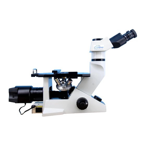
GX41
COMPACT INVERTED METALLURGICAL
MICROSCOPE
Optical Microscope and Accessory
This instruction manual is for the Olympus Compact Inverted Metallurgical Microscope Model GX41.
To ensure the safety, obtain optimum performance and to familiarize yourself fully with the use of
this microscope, we recommend that you study this manual thoroughly before operating the micro-
scope.
Retain this instruction manual in an easily accessible place near the work desk for future reference.
A X 7 5 8 9
Advertisement
Table of Contents

Related Manuals for Olympus GX41


Summary of Contents for Olympus GX41
- Page 1 MICROSCOPE Optical Microscope and Accessory This instruction manual is for the Olympus Compact Inverted Metallurgical Microscope Model GX41. To ensure the safety, obtain optimum performance and to familiarize yourself fully with the use of this microscope, we recommend that you study this manual thoroughly before operating the micro- scope.
- Page 2 Refer to your local Olympus distributor in EU for return and/or collection systems available in your country. NOTE: This product has been tested and found to comply with the limits for a Class A digital device, pursuant to Part 15 of the FCC Rules.
-
Page 3: Table Of Contents
GX41 Correct assembly and adjustments are indispensable for the microscope to manifest its full performance. If you want to assemble the microscope by yourself, see chapter 10, “ASSEMBLY” (pages 21 to 24) first. For the modules for which separate instruction manuals are provided, also refer to the assembly description in their manuals. -
Page 5: Important - Be Sure To Read This First For Safe Use Of The Equipment
6V30WHAL (Phillips 5761) Halogen bulb, 6V 30WHAL (Philips 5761) 6. Always use the power cord provided by Olympus. If no power cord is provided, please select the power cord by referring to the section “PROPER SELECTION OF THE POWER SUPPLY CORD” at the end of this instruc- tion manual. - Page 6 1) Close to the air inlet or ventilator of an air conditioning unit. 2) Locations with strong vibrations and severe temperature fluctuations. 3) Close to equipment that generates excessive noise (including non-Olympus products). 4) Places exposed to direct sunlight. 5) Dusty places with high temperature and humidity.
-
Page 7: Nomenclature
NOMENCLATURE }The modules shown below are examples of those used in a typical system. Certain modules are usable even when they are not mentioned below. For these modules, refer to the latest catalogues or contact Olympus. Objective Stage Center Plate ·... -
Page 8: Controls
CONTROLS } If the microscope has not been assembled yet, see chapter 10, “ASSEMBLY” (pages 21 to 24) first. 9 Interpupillary distance 5 Specimen holder (Page 7) scale (Page 9) 4 Stage plate (Page 7) Stage plate holder a Aperture iris diaphragm lever (Page 14) 9 Diopter adjustment... -
Page 9: Summary Of Observation Procedures
GX41 SUMMARY OF OBSERVATION PROCEDURES }The controls with numbers in circle are shown on the page on the left. For the simplified polarized light observation, see the special chapter on page 15. [Controls] [Page] @ Main switch (P. 6) Set the main switch to “ I ” (ON). -
Page 10: Using The Controls
USING THE CONTROLS 4-1 Microscope Frame Turning on the Light Source (Fig. 3) Set the main switch @ on the side panel of the microscope frame to “ I ” (ON). Fig. 3 Adjusting the Brightness Control Knob (Fig. 4) Turn the brightness control knob @ clockwise to raise the voltage and increase the light intensity. -
Page 11: Stage
GX41 4-2 Stage ² Placing the Specimen (Figs. 6 & 7) When using a mechanical stage 1. Set the stage plate @. (Fig. 6) 2. Place the specimen ² on the stage plate with the observation surface facing downward. (Fig. 6) # When setting the stage plate on the mechanical stage, use the stage plate holder ³... - Page 12 Observation Position Confirmation Mirror (Fig. 9) }To confirm the specimen observation position without looking at the speci- ² men from below the stage, mount the optional observation position con- firmation mirror @ on the stage. 1. Using the spanner ³ provided with the observation position confirma- ³...
-
Page 13: Observation Tube
GX41 4-3 Observation Tube Adjusting the Interpupillary Distance (Figs. 10 to 12) Be careful not to have your finger caught by the spaces on the binocular tube during the interpupillary distance adjustment. When using the U-CBI30-2/CTR30-2/CTBI observation tube While looking through the eyepieces, move both eyepieces until the left and right fields of view coincide completely. - Page 14 Adjusting the Diopter (Figs. 13 & 14) ² }When using the U-CTBI observation tube, align the white dot “ · ” on the diopter adjustment scale on the right eyepiece with the index line before proceeding to the following adjustment. 1.
- Page 15 GX41 Using the Eyepiece Micrometer Disk (Figs. 16 & 17) }When using the WHN10X-H (or WHN10X) eyepieces, an eyepiece micrometer disk can be inserted in one of them. However, if the eyepiece does not offer the helicoidal adjustment facility, observers with poor eyesight are recommended to wear eyeglasses be- cause they cannot focus the eye on the micrometer disk.
- Page 16 Selecting the Light Path for the Observation (Fig. 18) Tube (U-TR30-2 trinocular tube only) Move the light path selector knob @ to select the required light path. Light Path Symbol Intensity Ratio Applications Selector Knob Pushed in 100% for binocular Observation of dark eyepieces specimens...
-
Page 17: Illumination Unit
GX41 4-4 Illumination Unit Using the Filter (Figs. 20 to 23) }Use filters as needed to increase the accuracy of observation and photo- micrography. The 25LBD filter is especially recommended for observation and photo- micrography where high light intensity is required because it achieves the most natural color reproduction when the light source voltage is set to maximum (provided that a long-life halogen bulb is used). - Page 18 Using the Aperture Iris Diaphragm (Fig. 24) Aperture iris 70 – 80% diaphragm image }The aperture iris diaphragm determines the numerical aperture of the illumination system. It enables you to adjust the depth of focus, contrast 30 – 20% and resolution according to your requirements. ·...
-
Page 19: Simple Polarized Light Observation
GX41 SIMPLIFIED POLARIZED LIGHT OBSERVATION }Engage an analyzer and polarizer only when simplified polarized light observation is to be performed. Make sure they are both disengaged in ordinary observation since significant loss of light intensity occurs. (It is also required to insert the dummy slider in the analyzer inlet for ordinary observation.) -
Page 20: Photomicrography
PHOTOMICROGRAPHY }Use the U-CTR30-2 or U-TR30-2 trinocular tube for photomicrography, TV (video) camera observation or digital camera shooting. The trinocular tube allows the U-SPT or other TV adapter (which may also use an additional camera adapter) to be mounted on it. For details, also refer to the instruction manual for the modules used. -
Page 21: Troubleshooting Guide
Under certain conditions, performance of the microscope may be adversely affected by factors other than defects. If problems occur, please review the following list and take remedial action as needed. If you cannot solve the problem after checking the entire list, please contact Olympus for assistance. Trouble... - Page 22 Trouble Cause Remedy Page 2. Electric System a) The bulb flickers and the light —— The line voltage fluctuates. Use a voltage stabilizer. intensity is unstable. The bulb is almost burned out. Replace it with a new one. The power cord is not connected securely. Connect it securely.
-
Page 23: Specifications
GX41 SPECIFICATIONS Item Specifications 1. Optical system UIS2 (UIS) (Universal Infinity System) optics 6V30WHAL-L long-life halogen bulb. 6V30WHAL high-intensity halogen bulb. 2. Illumination system Hosobuchi G4 20H CF-6. Philips Type 5761. (Average bulb life: Approx. 2000 hrs. (Average bulb life: Approx. 100 hrs. -
Page 24: Optical Characteristics
UIS marking NA (Numerical of Aperture) NOTE Refer to the latest catalogue or consult Olympus for the updated information on the eyepieces and objec- Cover glass thickness tives that can be combined with this unit. -
Page 25: Assembly
“Placing the Specimen" on page 7. ** One of the following intermediate attachments can be mounted by dismounting the observation tube mount and attaching the GX41-EPA eye point adjuster: Applicable intermediate attachment: U-CA, GX-SPU, U-EPA2, U-ECA, U-DA or U-DO3. # For the U-DA/U-DO3, see the cautions in paragraph... - Page 26 10-2 Detailed Assembly Procedure Installing the Bulb and Lamp Socket (Figs. 29 & 30) Use only a designated bulb, which is the 6V30WHAL-L long-life halogen bulb (approx. life 2000 hours, Hosobuchi G4 20H CF-6) or the 6V30WHAL high-intensity halogen bulb (approx. life 100 ²...
- Page 27 GX41 Mounting the Mechanical Stage (Fig. 32) }The mechanical stage can be mounted on either the left or right side of the stage. The following instructions explain how to mount it on the right side. 1. Align the mechanical stage clamping screws ² with the two mounting ²...
- Page 28 Since the U-DO3 is positioned above the stage, the specimen height is limited to 80 mm or less. b) The assistant observer should take care not to touch the lamp socket of the GX41 because it is hot. If the heat hinders observation, please use the optional heat shield plate.
-
Page 29: Proper Selection Of The Power Supply Cord
If no power supply cord is provided, please select the proper power supply cord for the equipment by referring to “ Specifications ” and “ Certified Cord ” below: CAUTION: In case you use a non-approved power supply cord for Olympus products, Olympus can no longer warrant the electrical safety of the equipment. - Page 30 Table 2 HAR Flexible Cord APPROVAL ORGANIZATIONS AND CORDAGE HARMONIZATION MARKING METHODS Alternative Marking Utilizing Printed or Embossed Harmoniza- Black-Red-Yellow Thread (Length tion Marking (May be located on Approval Organization of color section in mm) jacket or insulation of internal wir- ing) Black Yellow...
-
Page 31: Lamp Socket Inspection Sheet
{If there is any ( ) mark noted, immediately stop use of the product, and consult Olympus for detailed inspections or replace the lamp socket. {If you detect an abnormality other than that listed below or with other Olympus product, also stop the use of the product and contact Olympus for detailed inspections. - Page 32 Manufactured by Shinjuku Monolith, 2-3-1 Nishi-Shinjuku, Shinjuku-ku, Tokyo 163-0914, Japan Distributed by 48 Woerd Avenue Waltham, MA 02453, U.S.A. 8F Olympus Tower, 446 Bongeunsa-ro, Gangnam-gu, Seoul, 06153 Korea Printed in Philippines AX7589 09...
Need help?
Do you have a question about the GX41 and is the answer not in the manual?
Questions and answers