ProMinent Sigma X Operating Instructions Manual
Diaphragm motor-driven metering pump
Hide thumbs
Also See for Sigma X:
- Supplementary instructions manual (24 pages) ,
- Quick start (2 pages)
Table of Contents
Advertisement
Quick Links
Operating instructions
Diaphragm motor-driven metering pump
Sigma X Control type — Sigma/ 2 - S2Cb
EN
Please carefully read these operating instructions before use. · Do not discard.
The operator shall be liable for any damage caused by installation or operating errors.
The latest version of the operating instructions are available on our homepage.
Part no. 982541
Original operating instructions (2006/42/EC)
Version: BA SI 105 01/22 EN
Advertisement
Table of Contents

Related Manuals for ProMinent Sigma X


Summary of Contents for ProMinent Sigma X
- Page 1 Operating instructions Diaphragm motor-driven metering pump Sigma X Control type — Sigma/ 2 - S2Cb Please carefully read these operating instructions before use. · Do not discard. The operator shall be liable for any damage caused by installation or operating errors.
- Page 2 Supplemental directives Supplementary information Read the following supplementary information in its entirety! Should you already know this information, you will benefit more from referring to the operating instructions. The following are highlighted separately in the document: Enumerated lists Fig. 1: Please read! Handling instructions ð...
-
Page 3: Table Of Contents
Table of contents Table of contents Identity code..................6 Safety chapter................. 9 2.1 Markings and warning symbols..........9 2.2 Intended use................9 2.3 Qualification of personnel............10 2.4 Isolating protective equipment..........12 Storage, Transport and Unpacking..........13 Overview of equipment and control elements....... 14 4.1 Control elements.............. - Page 4 Table of contents ‘Set time’ ................54 9.3.6 ‘Date’ ................. 54 9.3.7 ‘Timer’ .................. 54 ‘activation’ ............... 55 9.4.1 Timer ‘Setting the timer’ .............. 55 9.4.2 ‘Clear all’ ................56 9.4.3 9.4.4 Example................57 ‘Service’ ................57 9.5.1 ‘Password’ ................. 57 ‘Clear counter’...
- Page 5 20.2 Physiological safety............. 97 Diagrams for Setting the Capacity..........99 Declaration of Conformity for Machinery........100 Operating/Set-up overview of the Sigma X Control type..... 101 Operating menu of Sigma X Control type, complete....102 Continuous displays and secondary displays......106...
-
Page 6: Identity Code
Identity code Identity code Sigma X Control type – Sigma/ 2 - S2Cb Product range S2Cb Drive type Main power end, diaphragm Type Output _ _ _ _ Performance data at maximum back pressure and type: refer to nameplate on the pump... - Page 7 Identity code Sigma X Control type – Sigma/ 2 - S2Cb Aseptic clamp fitting DIN 11864-3 (Standard for hygienic design) Design with ProMinent logo without ProMinent logo Electric power supply 1-phase 100-230 V ± 10%, 50/60 Hz Cable and plug...
- Page 8 Identity code Sigma X Control type – Sigma/ 2 - S2Cb English Czech Danish Greek Spanish Estonian Finnish French Croatian Hungarian Italian Korean Lithuanian Latvian Dutch Polish Portuguese Romanian Russian Slovakian Slovenian Swedish Chinese ** Pump without HMI control unit...
-
Page 9: Safety Chapter
EHEDG hygienic requirements (www.ededg.org). Observe the general limitations with regard to viscosity limits, chem‐ ical resistance and density - see also the ProMinent Resistance List (in the Product Catalogue or at www.prominent.com)! All other uses or modifications are prohibited. -
Page 10: Qualification Of Personnel
Service Service refers to service technicians, who have received proven training and have been authorised by ProMinent or ProMaqua to work on the system. - Page 11 – Take into account the resistance of the wetted mate‐ rials and the ProMinent Resistance List when selecting the feed chemical - see the ProMinent Product Catalogue or visit ProMinent. CAUTION! Danger of personnel injury and material damage The use of untested third party parts can result in per‐...
-
Page 12: Isolating Protective Equipment
Safety chapter CAUTION! Danger from incorrectly operated or inadequately main‐ tained pumps Danger can arise from a poorly accessible pump due to incorrect operation and poor maintenance. – Ensure that the pump is accessible at all times. – Adhere to the maintenance intervals. WARNING! An on/off switch may not be fitted on the pump, dependent on the identity code and installation. -
Page 13: Storage, Transport And Unpacking
The "Decontamination Declaration Form" can be found at www.prominent.com. WARNING! Slings can tear ProMinent only supplies “non-reusable slings” in accord‐ ance with DIN EN 60005. They can tear with repeated use. – Destroy and remove the slings as soon as the pump has been lifted into its final position. -
Page 14: Overview Of Equipment And Control Elements
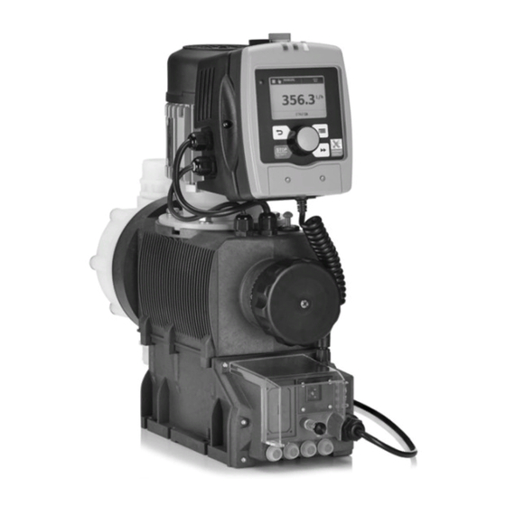
Overview of equipment and control elements Overview of equipment and control elements Overview of equipment P_SI_0189_SW Fig. 2: Overview of Sigma X - S2Cb equipment HMI control unit Frequency converter Drive unit Stroke length adjustment wheel Drive motor Liquid end... - Page 15 Overview of equipment and control elements P_SI_0180_SW Fig. 4: Control elements for HMI Sigma X Control type LCD screen [Menu] key Clickwheel [Priming] key [STOP/START] key [Back] key "Bluetooth active” display (blue) Fault indicator (red) Warning indicator (yellow) 10 Operating indicator (green) P_SI_0193_SW Fig.
-
Page 16: Control Elements
Overview of equipment and control elements 4.1 Control elements Use this overview to familiarise yourself with the keys and the other control elements on the pump! Pressure display, identifier and fault dis‐ plays on the LCD screen CONTACT memory open 12000 B1087 Fig. - Page 17 Overview of equipment and control elements Identifier Meaning [STOP/START] key. The pump was manually stopped using the The pump was remotely stopped (Pause) - via the "External" socket. The pump was stopped by an error. Only with cyclical batch metering: the pump is waiting for the next cycle. ‘memory’...
-
Page 18: Key Functions
Overview of equipment and control elements The pump only shows the metering volume and the capacity in the calibrated state in l or l/h or in gal or gal/h. 4.2 Key functions Application In the continuous displays In the menu [Back] press Move back to the previous menu... -
Page 19: Functional Description
Functional description Functional description 5.1 Pump The metering pump is an oscillating diaphragm pump, the stroke length of which can be adjusted. An electric motor drives it. The slide rod transmits the stoke motion to the diaphragms. Illustration of the stroke movement The stroke movement of the displacement body is continuously detected and regulated so that the stroke is performed according to a previously set ‘Metering’... -
Page 20: Liquid End
Functional description 5.2 Liquid end The diaphragm (2) hermetically shuts off the pump volume of the dosing head (4) towards the outside. The suction valve (1) closes as soon as the diaphragm (2) is moved in to the dosing head (4) and the feed chemical flows through the discharge valve (3) out of the dosing head. -
Page 21: Multi-Layer Safety Diaphragm
Functional description P_SI_0109 Fig. 10: Relief valve and integrated relief valve Spring, large Ball Rotary dial Hose connection 5.4 Multi-layer safety diaphragm With the visual diaphragm rupture sensor, the lowered red cylinder (6) springs forward beneath the transparent cover (7) so that it then becomes clearly visible Fig. -
Page 22: Functions
Functional description ‘Batch’ operating mode This operating mode provides the option of working with large transfer fac‐ tors (up to 99,999). Metering can be triggered either by pressing the [Clickwheel] or by a pulse received via the "External control" terminal or via a contact or a semiconductor switching element. -
Page 23: Options
Functional description The following functions are triggered by pressing a key: "Stop" function: the pump can be stopped without disconnecting it from the [STOP/START] . mains/power supply by pressing "Priming" function [Priming] . Priming can be triggered by pressing 5.7 Options Relay option The pump has several connection possibilities for the following options: "Output relay"... -
Page 24: Hierarchy Of Operating Modes, Functions And Fault Statuses
Functional description It also lights up with all other faults - refer to "Troubleshooting" chapter. Warning indicator (amber) The warning indicator lights up if the fluid level in the dosing tank falls below the first switching point of the level switch. It also lights up with all other warnings - refer to "Troubleshooting"... -
Page 25: Assembly
Assembly Assembly Compare the dimensions on the dimensional drawing with those of the pump. Clarify any deviations before assembling. 6.1 Base WARNING! Danger of electric shock If water or other electrically conducting liquids penetrate into the drive housing, in any other manner than via the pump's suction connection, an electric shock may occur. -
Page 26: Fastening
Assembly Discharge valve Dosing head Suction valve Ensure there is sufficient clearance (f) around the dosing head as well as the suction and discharge valve so that maintenance and repair work can be carried out on these components. P_MOZ_0017_SW Fig. 14: Clearance (f) 6.3 Fastening Liquid end alignment Dosing rate too low. -
Page 27: Installation
Installation Installation 7.1 Installation, hydraulic WARNING! Risk of fire with flammable feed chemicals – Only metering pumps with the identity code option "Multi-layer safety diaphragm with rupture signalling with electrical signal" are permitted to meter flam‐ mable media, with back pressures over 2 bar and if the operator puts in place the appropriate safety pre‐... - Page 28 The pump is supplied with PTFE moulded composite seals with a flare, which are used for the pump connectors, and which seal the connectors between grooved pump valves and ProMinent grooved inserts, see Ä Further information on page 27 .
-
Page 29: Relief Valve/Bleeder Valve
Installation Precise metering is only possible when the back – pressure is maintained above 1 bar at all times. If metering at atmospheric pressure, a back pres‐ – sure valve should be used to create a back pressure of approx. 1.5 bar. A back pressure valve, a spring-loaded injection valve, a relief valve, a P_SI_0022 foot valve or a liquid end do not represent absolutely leak-tight shut-off... -
Page 30: Diaphragm Rupture Sensor
Installation CAUTION! Danger of cracking Cracks on the PVT liquid end can occur if a metal over‐ flow line is connected to the relief valve. – Never connect a metal overflow line to the relief valve. CAUTION! Danger of the integral relief valve failing The integral relief valve no longer operates reliably with feed chemicals that have a viscosity of greater than 200 mPa s. -
Page 31: Basic Installation Notes
Installation 7.1.3 Basic installation notes Safety information CAUTION! Danger from rupturing hydraulic components Hydraulic components can rupture if the maximum per‐ missible operating pressure is exceeded. – Never allow the metering pump to run against a closed shut-off device. – With metering pumps without integral relief valve: Install a relief valve in the discharge line. -
Page 32: Installation, Electrical
Immediately disconnect the housing of the motor or electrical ancillaries from the mains/power supply if they have been damaged. Only return the pump to operation after a repair. Use ProMinent cables to avoid problems. What requires electrical installation? What requires electrical installation: Level switch... - Page 33 Installation Only with flammable media: WARNING! Fire danger The electric diaphragm rupture sensor must trigger an alarm and safely stop the pump as quickly as possible in the event of a diaphragm rupture. Only return the pump to service once a new diaphragm has been fitted.
- Page 34 Installation Fault indicating relay (24 V) Data Value Unit Maximum contact load at 24 V and 50/60 100 mA Minimum mechanical service life: 200,000 switching operations Pacing relay Data Value Unit Residual voltage max. at I = 1 µA 0.4 V off max Maximum current 100 mA...
- Page 35 Installation Current output Data Value Unit Open circuit voltage: Current range: 4 ... 20 mA Ripple, max.: 80 μA ss Load, max.: 250 Ω Fault indicating / pacing relay (24 V) Data Value Unit Residual voltage max. at I = 1 µA 0.4 V off max Maximum current...
- Page 36 2 white / Contact External activation 4 brown / GND Pulse frequency, e.g. contact water meter, PLC etc. Function "External Contact" (ProMinent universal control wire) 3 blue / Analog 5-core 2 white / Contact External 1 brown / Pause activation...
- Page 37 Installation P_BE_0014_SW Fig. 25: Pin assignment Function Parameter 1 = Pause input (activating func‐ Voltage with open contacts: approx. 5 V tion) Input resistance: 10 kΩ Control: Potential-free contact (approx. 0.5 mA) Semiconductor switch (residual voltage < 0.7 V) 2 = contact input Voltage with open contacts: approx.
- Page 38 Installation Block diagram Sigma Control Inputs Outputs Pump, inside Empty signal 3 brown / Pause Level Warning 2 blue / Alarm sensor 1 black / GND VDE cable: 2 green / NC (fault alert) 1 brown / 5 V Fault indicating 1 white / NO Stroke 2 white / Cod.
- Page 39 2 white / Contact External activation 4 brown / GND Pulse frequency, e.g. contact water meter, PLC etc. Function "External Contact" (ProMinent universal control wire) 3 blue / Analog 5-core 2 white / Contact External 1 brown / Pause activation...
-
Page 40: Hmi Operating Unit
Installation 7.2.3 HMI operating unit CAUTION! Danger of malfunctions Incorrect operation via the CAN bus will lead to malfunc‐ tions. – Do not connect any other control (e.g. DXCa) to the CAN socket when operating with the HMI con‐ nected. Connect the HMI to the CAN socket above the LEDs of the pump base if the pump is operated with HMI. -
Page 41: Basic Set-Up Principles
Please also refer to all the overviews covering – "Operating/set-up overview for Sigma X Control types" and "Operating menu for Sigma X Control types, complete" in the appendix and the "Overview of equipment and control elements" and "Control elements” chapters. - Page 42 Basic set-up principles [] Menu. To complete the setting: press ‘Menu’ via the [Menu] Alternatively: wait 60 seconds or exit the ‘End’ . key or using Confirming an entry [Clickwheel] . Briefly press the ð The software switches to the next menu point or back to the menu and saves the entry.
-
Page 43: Checking Adjustable Variables
Basic set-up principles To run through the figures again, if necessary (possibly because of an incorrect figure), when you get to the last figure press [Priming] again - see above Figure, point c). ð Now you can start from the beginning again. Confirming adjustable variables [Clickwheel] 1x. -
Page 44: Set Up/ 'Menu
‘Menu’ Set up/ Please also refer to all overviews covering "Operating/set up over‐ view" and "Operating menu for Sigma X Control type, complete" in the appendix and the "Overview of equipment" and "Control elements" chapters. The pump exits the menu and returns to a continuous display if [Menu] is pressed or if no key is pressed for 60 seconds. -
Page 45: Operating Mode
‘Menu’ Set up/ ‘Operating mode’ 9.3.1 ‘Menu / Information è Settings è Operating mode è ...’ ‘Manual’ 9.3.1.1 ‘Menu / Information è Settings è Operating mode è Manual’ ‘Manual’ operating mode allows you to operate the pump manually. The stroke rate can be set in the continuous display of this operating mode. - Page 46 ‘Menu’ Set up/ ‘Memory’ function extension ("memory" identi‐ Memory - Pulses not yet processed You can also activate the fier ). When ‘Memory’ is activated, the pump adds up the remaining strokes , which could not be processed, up to the maximum capacity of the stroke memory of 99,999 strokes.
- Page 47 ‘Menu’ Set up/ Table of examples Factor Pulse (sequence) Number of strokes (sequence) Step-up* 99.99 99.99 1.50 1.50 (1 / 2) 1.25 1.25 (1 / 1 / 1 / 2) Step-down** 0.50 0.10 0.01 0.25 0.40 2.5 (3 / 2) (1 / 1) 0.75 1.33 (2 / 1 / 1)
- Page 48 ‘Menu’ Set up/ The secondary display "Signal current" indicates the incoming current. You can select 5 types of current signal processing: ‘0 - 20 mA’ ‘4 - 20 mA’ ‘Linear curve ’ ‘Lower side band’ ‘Upper side band’ ‘Standard’ ‘0 - 20 mA’ At 0 mA the pump is stationary –...
-
Page 49: Metering
‘Menu’ Set up/ Using this type of processing, you can control a metering pump using the current signal as shown in the diagram below. You can enter the curve ‘Curve points’ menu. points I and F in the However, you can also control two metering pumps for different feed chemicals via a current signal (e.g. -
Page 50: Calibration
‘Menu’ Set up/ ‘Dosing profile’ - ‘Discharge optimized’ , the pressure stroke is elon‐ Metering optimised With gated and the suction stroke is executed as quickly as possible. This set‐ ting is suitable, among other things, for applications that require optimum mixing ratios and chemical mixing that is as continuous as possible. -
Page 51: Inputs/Outputs
‘Menu’ Set up/ Calibration process Record the level in the measuring cylinder. ‘Menu / Information è Settings è Calibrate’ ‘’ menu and Select the [Clickwheel] . press the ‘Start calibration’ (PUSH) menu item appears. ð The To start calibration, press the [Clickwheel] . - Page 52 ‘Menu’ Set up/ The setting options for the ‘Relay’ function only exist if a relay is fitted. Tab. 8: Relay, physical and pre-set to ... Identity code specification Relay, physical Pre-set to ... 1 x changeover contact 230 V – 8 A Fault indicating relay, N/C 2 x N/O 24 V –...
-
Page 53: System
‘Menu’ Set up/ ‘Relay2’ - see Ä Chapter 9.3.4 ‘ ‘Inputs/outputs’ ’ For more information on on page 51 . 9.3.4.4 ‘mA-Output (optional)’ ‘Menu / Information è Settings è Inputs/outputs è mA-Output ...’ è You can set which current range is to be used at the mA output here. ‘Function’... -
Page 54: Set Time
‘Menu’ Set up/ ‘System’ menu splits into the following sub-menus: ‘Bluetooth’ ‘Volume unit’ ‘Bluetooth ’ 9.3.5.1 ‘Menu / Information è Settings è System è Bluetooth è ...’ You can switch the pump’s Bluetooth communication on and off in the ‘Bluetooth’ sub-menu. The blue “Bluetooth active” LED lights up on the HMI. -
Page 55: Timer 'Activation
‘Menu’ Set up/ ‘activation’ 9.4.1 Timer ‘Menu / Information è Timer è Activation è ...’ ‘Activation’ to ‘active’ . To activate the timer, set ‘Setting the timer’ 9.4.2 A program set up with an uncalibrated pump will not function with the calibrated pump – and vice versa. ‘Menu / Information è... -
Page 56: Clear All
‘Menu’ Set up/ Time event Time ‘Hourly’ hourly at the xth minute ‘Daily (Mon-Sun)’ daily at the time mm.ss, Monday to Sunday ‘Weekdays1 (Mo-Fr)’ daily at the time mm.ss, Monday to Friday ‘Weekdays1 (Mo-Sa)’ daily at the time mm.ss, Monday to Saturday ‘Weekend (Sa+Su)’... -
Page 57: Example
‘Menu’ Set up/ ‘Clear all’ menu to clear all commands (the program). Use the 9.4.4 Example Example of "Weekday metering" The pump is to meter 2 litres every half hour every weekday (Mon-Fri) between 8:00 and 11:00: Com‐ Time event Time of day Action Capacity... -
Page 58: Log Book
‘Menu’ Set up/ ‘All’ ‘Stroke counter’ (total number of strokes) ‘Volume counter’ (total litres) ‘Contact memory’ To clear: exit the menu by briefly pressing the [Clickwheel] . The values have increased since commissioning of the pump, the last cali‐ bration or the last deletion. ‘Log book’... -
Page 59: Spare Parts Kit Part Number: Xxxxxxx
‘Menu’ Set up/ You can read off the part number (order number) of the correct diaphragm here. ‘Spare parts kit part number: XXXXXXX’ 9.5.7 ‘Menu / Information è Service Spare parts kit part number: XXXXXXX è ...’ è You can read off the part number (order number) of the correct spare parts kit here. -
Page 60: Start Up
Start up Start up Safety information WARNING! Fire hazard with flammable media Only with flammable media: They can be ignited by oxygen. – The pump may not work if there is a mixture of feed chemical with oxygen in the liquid end. A specialist may need to take appropriate actions (using inert gas, ...). - Page 61 Start up CAUTION! Prior to commissioning, check that the pump and corre‐ sponding ancillary equipment is connected in compli‐ ance with the regulations! Observe the technical data CAUTION! Danger of material damage Observe the details in the chapter "Technical data" (pressure, viscosity, resistance, etc.).
- Page 62 Start up Avoid particles The valves may no longer close properly with feed chemicals with a particle size of greater than 0.3 mm. Install a suitable filter in the suction line. – Using the integral relief valve CAUTION! Danger due to incorrect use of the integral relief valve The integral relief valve can only protect the motor and the gear, and then only against impermissible positive pressure that is caused by the metering pump itself.
- Page 63 Start up Adjusting the stroke length Only adjust the stroke length when the pump is running. This is easier and also better for the pump. P_SI_0095_SW Fig. 32: Adjusting the stroke length 100% = 4 rotations 25 % = 1 rotation 0.5 % = 1 scale mark on stroke adjustment dial Earthing lines Check whether the earthing lines in the pump's electrical units are cor‐...
-
Page 64: Operation
Operation Operation WARNING! Fire hazard with flammable media Only with flammable media: They can be ignited by oxygen. – The pump may not work if there is a mixture of feed chemical with oxygen in the liquid end. A specialist may need to take appropriate actions (using inert gas, ...). - Page 65 Operation List of directly changeable variables: Capacity Stroke rate Factor Contact volume Batch volume Set-up overview of the Sigma X Control type Continuous display Stop/start pump STOP STOP START START Priming Start batch (only in "Batch" mode) Acknowledge errors Check adjustable variables...
-
Page 66: Maintenance
Maintenance Maintenance 12.1 Maintenance safety notes CAUTION! Warning of feed chemical spraying around Feed chemical may spray out of the hydraulic compo‐ nents if they are tampered with or opened due to pres‐ sure in the liquid end and adjacent parts of the system. –... -
Page 67: Standard Liquid Ends
Maintenance 12.2 Standard liquid ends: Interval Maintenance work Personnel After approx. 5,000 oper‐ Change gear oil - refer to "Changing gear oil" in this chapter. Instructed personnel ating hours Quarterly Check the oil level. Quarterly* Check that the metering lines are tight at the liquid end and Technical personnel check for leak-tightness. - Page 68 Maintenance Changing gear oil Draining gear oil Unscrew the vent screw (1). Place an oil trough under the oil drainage plug (2). Unscrew the oil drainage plug (2) from the power end housing. Allow the gear oil to drain out of the power end. Screw in the oil drainage plug (2) with a new seal.
-
Page 69: Repair
Repair Repair 13.1 Safety information, repair WARNING! Fire hazard with flammable media Only with flammable media: They can be ignited by oxygen. – The pump may not work if there is a mixture of feed chemical with oxygen in the liquid end. A specialist may need to take appropriate actions (using inert gas, ...). - Page 70 Repair Only with "Physiologically safe" design: WARNING! Product can be dangerously contaminated Only use the spare parts from the "Physiologically safe" spare parts kits. Personnel: Technical personnel Repairing ball valves CAUTION! Warning of personal injury and material damage Feed chemical may escape from the liquid end, for example, if ball valves are not repaired correctly.
-
Page 71: Replacing The Diaphragm
Repair 13.3 Replacing the diaphragm Third-party spare parts for the pumps can lead to prob‐ lems when pumping. – Only use original spare parts. Use the correct spare parts kits. In the event of – doubt, refer to the exploded views and ordering information in the appendix. - Page 72 Should this not work, remove dirt or swarf from the thread and screw the diaphragm correctly onto the drive axle this time. ð If this is still unsuccessful, contact ProMinent-ProMaqua Service. Place the dosing head with the screws onto the diaphragm - the suction connector should be pointing downwards when the pump is subsequently installed.
- Page 73 Repair Reassemble the clean diaphragm rupture sensor with the clean piston. Test the diaphragm rupture sensor: Optical diaphragm rupture sensor Unscrew the transparent cover from the diaphragm rupture sensor. Press the red cylinder into the diaphragm rupture sensor until the cylinder engages.
- Page 74 Repair P_SI_0038 Fig. 38: Cross-section through the liquid end Suction valve Diaphragm Discharge valve Dosing head Backplate 13 Safety diaphragm...
-
Page 75: Troubleshooting
Troubleshooting Troubleshooting 14.1 Safety information, troubleshooting WARNING! Fire hazard with flammable media Only with flammable media: They can be ignited by oxygen. – The pump may not work if there is a mixture of feed chemical with oxygen in the liquid end. A specialist may need to take appropriate actions (using inert gas, ...). -
Page 76: Faults Without Error Message
Troubleshooting 14.2 Faults without error message Fault description Cause Remedy Personnel Pump does not prime Minor crystalline deposits on Take the suction hose out of the supply tank Technical per‐ despite full stroke motion the ball seat due to the and thoroughly flush out the liquid end. -
Page 77: Warning Messages
Troubleshooting Fault description Cause Remedy Personnel The diaphragm is ruptured. Replace the diaphragm and Technical The DIA "Diaphragm" symbol appears flashing on the LCD screen plus the check the diaphragm rup‐ personnel ‘Diaphragm rupture’ 38 error message, and ture sensor - refer to the the pump stops. -
Page 78: All Other Faults
‘CANopen pump’ 8. 14.5 All other faults Please contact the responsible ProMinent subsidiary or representative - see www.prominent.com - "Contact" - "Your contacts worldwide" or pos‐ sibly the Legal Notices in these operating instructions. 14.6 Log book Tab. 11: Input information... -
Page 79: Warning Messages In The Log Book
Troubleshooting 14.6.1 Warning messages in the log book Tab. 12 Description Float switch input reports feed chemical nearing an end Calibration warning: Appears if the stroke length is adjusted above the tolerance and the pump therefore has to be recalibrated The number of defective strokes permitted has been exceeded The diaphragm rupture sensor reports a diaphragm rupture The stroke length has been modified beyond the tolerance limit with the pump locked... -
Page 80: Events In The Log Book
Troubleshooting Message no. Description Error in the intermediate circuit voltage The 5 V at the DFM input has short circuited An optional module was inserted into the pump, which cannot be used. Subscriber software is incompatible with the other subscribers The pump is blocked and is not running Missing or defective hall sensor Shut-down in the event of overpressure, slow... -
Page 81: Decommissioning
Decommissioning Decommissioning Decommissioning WARNING! Fire hazard with flammable media Only with flammable media: They can be ignited by oxygen. – The pump may not work if there is a mixture of feed chemical with oxygen in the liquid end. A specialist may need to take appropriate actions (using inert gas, ...). - Page 82 Decommissioning WARNING! Warning of eye injuries When opening the relief valve, a spring under high ten‐ sion can jump out. – Wear protective glasses. CAUTION! Danger of damage to the device The device may be damaged by incorrect and improper storage and transport.
-
Page 83: Technical Data
Technical data Technical data 16.1 Performance data S2Cb Type Minimum pump capacity at maximum Max. Suction Permissible Connector back pressure stroke lift priming pres‐ size rate sure, suction side Strokes/ ml/stroke m water G-DN column 16050 PVT 11.4 1 male - 16050 SST 11.4 1 male -... -
Page 84: Viscosity
Technical data 16.2 Viscosity Tab. 13: The liquid ends are suitable for the following viscosity ranges: Design Stroke rate, max. Viscosity Strokes/min mPas Standard 0 ... 200 With valve springs 200 ... 500 With valve springs and suction- 500 ... 1000* side feed * Only when the installation is correctly adjusted. -
Page 85: Air Humidity
Technical data Data Value Unit Minimum temperature -10 °C SST liquid end Data Value Unit Max. temperature long-term at max. oper‐ 90 °C ating pressure Max. temperature for 15 min at max. 2 bar 120 °C Minimum temperature -10 °C 16.5.3 Air humidity Air humidity... -
Page 86: Diaphragm Rupture Sensor
Value Order no. Fuse, internal 6.3 AT - (1.5 kA) 732379 INFORMATION!: Only use the original ProMinent fuses. It is not sufficient to use a fuse with the above fuse rating. 16.8 Diaphragm rupture sensor Contact (standard) Tab. 15: Contact loading, max. -
Page 87: Relays
Technical data Cable colour Polarity blue brown 16.9 Relays INFORMATION!: The technical data for the relays is contained in the chapter "Installation, electrical". 16.10 Gear oil Manufacturer Name Viscosity class Order no. Volume Volume, required (ISO 3442) approx. Mobil Mobil Gear 634 VG 460 1004542 1.0 l... -
Page 88: Dimensional Drawings
Dimensional drawings Dimensional drawings Compare the dimensions on the dimension sheet – and pump. All dimensions are in mm. – HMI and wall bracket 21.5 4.5 4.5 72.5 P_SI_0192_SW Fig. 39: Dimensions in mm... - Page 89 Dimensional drawings Sigma X Control type - Sigma/ 2 - S2Cb P_SI_0182_SW Fig. 40: View is not strictly binding - dimensions in mm Type Connector ØG 16050, DN 15 G1 M 16090, 16130 16050, DN 15 G1 M 16090, 16130...
-
Page 90: Motor Data Sheets
This information is supplied without liability. Les données techniques correspondent au descriptif du fabricant des moteurs. Les données techniques des moteurs similaires chez d’ autres fabricants varient très peu. Données sont d’ ordre général. ProMinent Dosiertechnik GmbH . 69123 Heidelberg . Germany Nr./No. MD-1040790... -
Page 91: Liquid Ends Sigma/ 2
Liquid ends Sigma/ 2 Liquid ends Sigma/ 2 Liquid end Sigma/ 2 130-DN 15 and 350- DN 25 PVT P_SI_0024 Fig. 41: Liquid end Sigma/ 2 130-DN 15 and 350-DN 25 PVT Pos. Description Spring * Ball Ball seat Diaphragm rupture sensor, visual * Valve Multi-layer diaphragm The items listed are included in the spare parts kit. - Page 92 Liquid ends Sigma/ 2 Tab. 17: Order no. for liquid end for Sigma/ 2, 130-DN 15 PVT Spare part 16050 16090 16130 Liquid end 1029763 1029763 1029763 Spare parts kit 1035951 1035951 1035951 Diaphragm rupture 1033323 1033323 1033323 sensor, visual Valve 792517 792517...
- Page 93 Liquid ends Sigma/ 2 Pos. Description Type 16050, Type 07120, Type 04350 16090, 16130 07220 Relief valve, complete 10 bar PVA 1018947 Relief valve, complete 7 bar PVA 740811 Relief valve, complete 4 bar PVA 740812 * The items listed are included in the spare parts kit. Springs made from Hastelloy C, O-rings from FPM-A and EPDM. Technical changes reserved.
- Page 94 Liquid ends Sigma/ 2 Liquid end Sigma/ 2 130 and 350 SST P_SI_0025_SW Fig. 44: Liquid end Sigma/ 2 130 and 350 SST Pos. Description Spring * Ball Ball seat Diaphragm rupture sensor, visual * Valve * Multi-layer diaphragm The items listed are included in the spare parts kit. * Special accessories (not included in the spare parts kit).
- Page 95 Liquid ends Sigma/ 2 Spare part 16050 16090 16130 Diaphragm rupture 1033323 1033323 1033323 sensor, visual Valve 809404 809404 809404 Multi-layer diaphragm 1029771 1029771 1029771 Tab. 20: Order no. for liquid end for Sigma/ 2, 350-DN 25 SST Spare part 07120 07220 04350...
- Page 96 Liquid ends Sigma/ 2 Pos. Description Type 16050, Type 07120, Type 04350, 16090, 16130 07220 Relief valve, complete 16 bar SSA 1019246 Relief valve, complete 7 bar SSA 740815 Relief valve, complete 4 bar SSA 740814 * The items listed are included in the spare parts kit. Springs made from Hastelloy C, O-rings from FPM-A and EPDM. Technical changes reserved.
-
Page 97: Wearing Parts For S2Cb
Wearing parts for S2Cb Wearing parts for S2Cb Refer also to the previous chapter. 20.1 Standard HMI spare parts Spare part Order no. HMI wall bracket 1036683 HMI protective film 1083680 20.2 Physiological safety Spare parts kits Tab. 21: Scope of delivery with PVT material version 1 x diaphragm, 2 x valve balls, 1 x suction valve complete, 1 x discharge valve complete 1 x elastomer sealing set (EPDM) 2 x ball seat housings, 2 x ball seat discs, 4 x composite seals... - Page 98 Wearing parts for S2Cb Material version Liquid end Suction / pressure Seals* / ball seat Balls Integrated bleed connector valve or relief valve PVDF PVDF PTFE / PVDF Ceramic / glass ** PVDF / EPDM Stainless steel Stainless steel PTFE / PVDF Stainless steel Stainless steel / 1.4404...
-
Page 99: Diagrams For Setting The Capacity
Diagrams for Setting the Capacity Diagrams for Setting the Capacity S2Cb C [l/h] 04350 07220 07120 16130 16090 16050 S [%] C [l/h] 04350 07220 07120 16130 16090 16050 p [bar] Fig. 47: A) Capacity C at maximum back pressure dependent on the stroke length s. B) Capacity C dependent on the back pressure p. -
Page 100: Declaration Of Conformity For Machinery
Appendix I, No. 1.5.1 of the Machinery Directive EMC Directive (2014/35/EU) Harmonised standards applied, in EN ISO 12100:2010 particular: EN 809:1998 + A1:2009 + AC:2010 EN 61010-1:2010 EN 61000-6-2:2005 + AC:2005 EN 61000-6-4:2007 + AC:2011 Date: 20.04.2016 View the EC Declaration of Conformity at www.prominent.com. -
Page 101: Operating/Set-Up Overview Of The Sigma X Control Type
Operating/Set-up overview of the Sigma X Control type Operating/Set-up overview of the Sigma X Control type Continuous display Stop/start pump STOP STOP START START Priming Start batch (only in "Batch" operating mode) Acknowledge errors Check adjustable variables Change directly adjustable variables... -
Page 102: Operating Menu Of Sigma X Control Type, Complete
Operating menu of Sigma X Control type, complete Operating menu of Sigma X Control type, complete 1st level Information Versions CTRL hardware CTRL software HMI software Time Date Serial number Identity code Part name Part device address Operating mode Manual... - Page 103 Operating menu of Sigma X Control type, complete 1st level Relay 1 Relay1 type Warning Error Warning + error Warning + Error + Stop Stop. Stroke rate Pump inactive Relay 1 polarity normally open (NO) normally closed (NC) Relay 2...
- Page 104 Operating menu of Sigma X Control type, complete 1st level Summer time February begins in March April Sunday the 1st, 2nd, 3rd, 4th, Summer time ends August September October November Sunday the 1st, 2nd, 3rd, 4th, Town Northern Hemi‐ sphere Southern Hemi‐...
- Page 105 Operating menu of Sigma X Control type, complete 1st level Diaphragm part number: XXXXXXX Spare parts kit part number: XXXXXXX Language English German Frenchç Spanishñ Italian Menus may be missing or added depending on the design and equipment on the pump.
-
Page 106: Continuous Displays And Secondary Displays
Continuous displays and secondary displays Continuous displays and secondary displays... - Page 107 Continuous displays and secondary displays...
-
Page 108: Index
Index Index 1, 2, 3 ... Clearing the program ..... . . 56 Climate ....... . . 85 "External control"... - Page 109 Index Extended, Analogue ......48 External analogue ......24 Language .
- Page 110 Index Optional module ......14 Set up, chapter ......44 Options .
- Page 111 Index Wall bracket ......88 Warning ....... . 52 Warning indicator .
- Page 112 ProMinent GmbH Im Schuhmachergewann 5 - 11 69123 Heidelberg Germany Telephone: +49 6221 842-0 Fax: +49 6221 842-419 Email: info@prominent.com Internet: www.prominent.com 982541, 4, en_GB © 2022...
Need help?
Do you have a question about the Sigma X and is the answer not in the manual?
Questions and answers