Table of Contents
Advertisement
Operating instructions
Diaphragm Motor-driven Metering Pump
Sigma X Control type — Sigma/ 2 - S2Cb
EN
Please carefully read these operating instructions before use. · Do not discard.
The operator shall be liable for any damage caused by installation or operating errors.
The latest version of the operating instructions are available on our homepage.
Part no. 982541
Original operating instructions (2006/42/EC)
BA SI 079 07/18 EN
Advertisement
Table of Contents

Related Manuals for ProMinent Sigma2 S2Cb


Summary of Contents for ProMinent Sigma2 S2Cb
- Page 1 Operating instructions Diaphragm Motor-driven Metering Pump Sigma X Control type — Sigma/ 2 - S2Cb Please carefully read these operating instructions before use. · Do not discard. The operator shall be liable for any damage caused by installation or operating errors. The latest version of the operating instructions are available on our homepage.
- Page 2 Supplemental directives Supplementary information Read the following supplementary information in its entirety! Should you already know this information, you will benefit more from referring to the operating instructions. The following are highlighted separately in the document: Enumerated lists Fig. 1: Please read! Handling instructions ð...
-
Page 3: Table Of Contents
Table of contents Table of contents Identity code..................5 Safety Chapter................. 8 Storage, Transport and Unpacking..........12 Overview of equipment and control elements....... 13 4.1 Control elements..............15 4.2 Key functions................. 17 Functional description..............18 5.1 Pump..................18 5.2 Liquid end................19 5.3 Bleed valve and integrated relief valve ........ - Page 4 Table of contents ‘Display’ ................61 9.5.4 ‘HMI logout’ ............... 61 9.5.5 ‘Diaphragm part number: XXXXXXX’ ........ 61 9.5.6 ‘Spare parts kit part number: XXXXXXX’ ......62 9.5.7 ‘Language’ ................62 Start up..................63 Operation..................67 11.1 Manual operation..............67 Maintenance..................
-
Page 5: Identity Code
Identity code Identity code Sigma X Control type – Sigma/ 2 - S2Cb Product range S2Cb Power end type Main power end, diaphragm Type Capacity _ _ _ _ _ Performance data at maximum back pressure and type: refer to nameplate on the pump housing Dosing head material PVDF... - Page 6 Identity code Sigma X Control type – Sigma/ 2 - S2Cb Union nut and SS welding sleeve Design With ProMinent ® logo Without ProMinent ® logo Leak-tightness according to NEMA 4x Electric power supply 1-phase, 100-230 V ± 10%, 50/60 Hz...
- Page 7 Identity code Sigma X Control type – Sigma/ 2 - S2Cb with access con‐ trol, dynamic metering monitor HMI with Blue‐ tooth HMI with Wi-Fi Language German English Spanish French Italian FPM = fluorine rubber ** Pump without HMI control unit...
-
Page 8: Safety Chapter
EHEDG (www.ededg.org). Observe the general limitations with regard to viscosity limits, chem‐ ical resistance and density - see also the ProMinent Resistance List (in the Product Catalogue or at www.prominent.com)! All other uses or modifications are prohibited. - Page 9 Service Customer Service department refers to service technicians, who have received proven training and have been authorised by ProMinent or Pro‐ Maqua to work on the system.
- Page 10 – Take into account the resistance of the wetted mate‐ rials and the ProMinent Resistance List when selecting the feed chemical - see the ProMinent Product Catalogue or visit ProMinent. CAUTION! Danger of personnel injury and material damage The use of untested third party parts can result in per‐...
- Page 11 Safety Chapter CAUTION! Danger from incorrectly operated or inadequately main‐ tained pumps Danger can arise from a poorly accessible pump due to incorrect operation and poor maintenance. – Ensure that the pump is accessible at all times. – Adhere to the maintenance intervals. WARNING! An on/off switch may not be fitted on the pump, dependent on the identity code and installation.
-
Page 12: Storage, Transport And Unpacking
The "Decontamination Declaration Form" can be found at www.prominent.com. WARNING! Slings can tear ProMinent only supplies “non-reusable slings” in accord‐ ance with DIN EN 60005. They can tear with repeated use. – Destroy and remove the slings as soon as the pump has been lifted into its final position. -
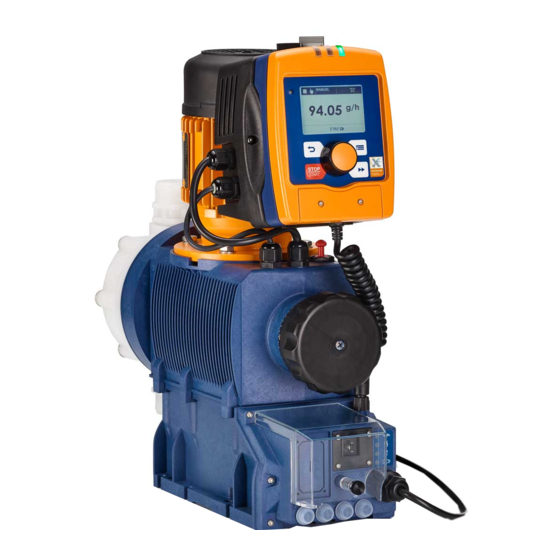
Page 13: Overview Of Equipment And Control Elements
Overview of equipment and control elements Overview of equipment and control elements Overview of equipment P_SI_0189_SW Fig. 2: Overview of Sigma X - S2Cb equipment HMI control unit Frequency converter Drive unit Stroke length adjustment wheel Drive motor Liquid end Diaphragm rupture sensor Control elements P_SI_0088_SW_2... - Page 14 Overview of equipment and control elements P_SI_0180_SW Fig. 4: Control elements for HMI Sigma X Control type LCD screen [Menu] key Clickwheel [Priming] key [STOP/START] key [Back] key "Bluetooth active” display (blue) Fault indicator (red) Warning indicator (yellow) 10 Operating indicator (green) P_SI_0193_SW Fig.
-
Page 15: Control Elements
Overview of equipment and control elements "Level switch" terminal "CAN bus" socket (external) LEDs (as Fig. 4) and CAN bus status LED (external) not shown Stroke length adjustment wheel 4.1 Control elements Use this overview to familiarise yourself with the keys and the other control elements on the pump! Pressure display, identifier and fault dis‐... - Page 16 Overview of equipment and control elements Tab. 1: Identifier and error displays: Identifier Meaning The pump is working or waiting for a starting signal. [STOP/START] key. The pump was manually stopped using the The pump was remotely stopped (Pause) - via the "External" socket. The pump was stopped by an error.
-
Page 17: Key Functions
Overview of equipment and control elements The pump only shows the metering volume and the capacity in the calibrated state in l or l/h or in gal or gal/h. 4.2 Key functions Application In the continuous displays In the menu [Back] press Move back to the previous menu... -
Page 18: Functional Description
Functional description Functional description 5.1 Pump The metering pump is an oscillating diaphragm pump, the stroke length of which can be adjusted. An electric motor drives it. The slide rod transmits the stoke motion to the diaphragms. Illustration of the stroke movement The stroke movement of the displacement body is continuously detected and regulated so that the stroke is performed according to a previously set ‘Metering’... -
Page 19: Liquid End
Functional description With a priming optimised metering profile, the suction stroke is elongated as much as possible, which facilitates the precise and problem-free metering of viscous and gaseous media. Select this setting to minimise the NPSH value as well. P_SI_0104_SW 5.2 Liquid end The diaphragm (2) hermetically shuts off the pump volume of the dosing head (4) towards the outside. -
Page 20: Multi-Layer Safety Diaphragm
Functional description The integral relief valve can only protect the motor and the gear, and then only against impermissible positive pressure that is caused by the metering pump itself. It cannot protect the system against positive pres‐ sure. The integral relief valve works as a bleed valve as soon as the rotary dial (3) is turned to "open": The valve opens and the liquid end can be bled. -
Page 21: Functions
Functional description ‘Manual’ operating mode: The stroke rate is set manually on the control unit. ‘Batch’ operating mode This operating mode provides the option of working with large transfer fac‐ tors (up to 99,999). Metering can be triggered either by pressing the [Clickwheel] or by a pulse received via the "External control"... -
Page 22: Options
Functional description The following functions are available as standard: "Level switch" function: Information about the liquid level in the dosing tank is reported to the pump control. To do this, a two-stage level switch must be fitted, which is connected to the "Level switch" terminal. "Pause"... -
Page 23: Lcd Screen
Functional description 5.8.1 LCD screen ‘Error’ appears and an additional error mes‐ If a fault occurs, the identifier sage – see “Troubleshooting” chapter 5.8.2 LED displays Pump device LEDs - see "Troubleshooting" chapter Fault indicator (red) The fault indicator lights up if the fluid level in the dosing tank falls below the second switching point of the level switch (20 mm residual filling level in the dosing tank). - Page 24 Functional description Comments: re 1 - “Priming" can take place in any mode of the pump (providing it is working). re 2 - "Fault", "Stop" and "Pause" stop everything apart from "Priming". re 3 - The "Auxiliary frequency" stroke rate always has priority over the stroke rate specified by an operating mode listed under 4.
-
Page 25: Assembly
Assembly Assembly Compare the dimensions on the dimension sheet with those of the pump. Base WARNING! Danger of electric shock If water or other electrically conducting liquids penetrate into the drive housing, in any other manner than via the pump's suction connection, an electric shock may occur. –... - Page 26 Assembly Discharge valve Dosing head Suction valve Ensure there is sufficient free space (f) around the dosing head as well as the suction and discharge valve so that maintenance and repair work can be carried out on these components. P_MOZ_0017_SW Fig.
-
Page 27: Installation
Installation Installation CAUTION! Danger of injury to personnel and material damage Disregard of technical data during installation may lead to personal injuries or damage to property. – Observe the technical data - refer to the "Technical data" chapter and, where applicable, the operating instructions for the accessories. - Page 28 Installation CAUTION! Suction problems are possible The valves may no longer close properly with feed chemicals with a particle size of greater than 0.3 mm. – Install a suitable filter in the suction line. CAUTION! Warning of the discharge line rupturing With a closed discharge line (e.g.
- Page 29 P_SI_0021 grooved pump valves and ProMinent grooved Ä Further information on page 27 . Fig. 16: Moulded composite seals with inserts - see corrugated insert –...
- Page 30 Installation Integral relief valve or integral bleeder valve WARNING! Product can be dangerously contaminated Only with "Physiologically safety with regard to wetted materials” version: If the integral bleed valve or the integral relief valve opens, the feed chemical comes into contact with phys‐ iologically harmful seals.
-
Page 31: Basic Installation Notes
Installation CAUTION! Warning of leaks Feed chemical, which remains in the overflow line at the relief valve or bleeder valve, can attack the valve or cause it to leak – Route the overflow line with a continuous slope and moreover with the hose nozzle pointed downwards - see . -
Page 32: Installation, Electrical
Installation CAUTION! Hazardous feed chemicals can escape With hazardous feed chemicals: Hazardous feed chem‐ ical can leak out when using conventional bleeding pro‐ cedures with metering pumps. – Install a bleed line with a return into the storage tank. Shorten the return line so that it does not dip into the feed chemical in the storage tank. -
Page 33: Control Connectors
Only return the pump to service after an authorised repair. CAUTION! Use ProMinent cables to avoid unnecessary problems. What requires electrical installation? What requires electrical installation? Level switch Diaphragm rupture sensor, electrical (optional) - Page 34 Installation Only with flammable media: WARNING! Fire danger The electric diaphragm rupture sensor must stop the pump immediately after a diaphragm rupture and trigger an alarm. The pump must only be returned to Service once a new diaphragm has been fitted. 7.2.1.1 Relay 7.2.1.1.1...
- Page 35 Installation 7.2.1.1.2 Fault indicating and pacing relay option The first switch is a relay. The pacing output is electrically-isolated by means of an optocoupler with a semiconductor switch. If another switching function is required, the pump can be reprogrammed ‘Relay’ menu. in the The relay can be retrofitted and is operational once it has been plugged into the relay board.
- Page 36 Installation 7.2.1.1.3 Current output and fault indicating / pacing relay (24 V) The module can be retrofitted and operates once it is plugged into the module board. The variable to be signalled for the current output can be selected in the ‘ANALOGUE OUTPUT’...
- Page 37 2 white / Contact External activation 4 brown / GND Pulse frequency, e.g. contact water meter, PLC etc. Function "External Contact" (ProMinent universal control wire) 3 blue / Analog 5-core 2 white / Contact External 1 brown / Pause activation...
- Page 38 Installation Technical data "External control" Semi-conductor switch elements with a residual voltage of -0.7 V (e.g. transistors in open-collector circuits) or contacts (relays) can be used as input switch elements. P_BE_0014_SW Pin 1 = Pause input (activating func‐ Voltage with open contacts: approx.
- Page 39 Installation Block diagram Sigma Control Inputs Outputs Pump, inside Empty signal 3 brown / Pause Level Warning 2 blue / Alarm sensor 1 black / GND VDE cable: 2 green / NC (fault alert) 1 brown / 5 V Fault indicating 1 white / NO Stroke 2 white / Cod.
-
Page 40: Hmi Operating Unit
2 white / Contact External activation 4 brown / GND Pulse frequency, e.g. contact water meter, PLC etc. Function "External Contact" (ProMinent universal control wire) 3 blue / Analog 5-core 2 white / Contact External 1 brown / Pause activation... -
Page 41: Pump, Power Supply
Installation If the pump is operated without the HMI, the sealing cap supplied must be plugged into the CAN socket above the LEDs of the pump base. CAUTION! Risk of short circuit A short circuit may occur in the pump if liquid penetrates into the CAN socket. -
Page 42: Other Units
Installation CAUTION! Pump can be damaged The pump can only be stopped when running via an: – External cable [Stop] key. – Use a relay or a contactor if the pump is to be definitively actuated via the mains cable. However, take into account the pump’s starting current. -
Page 43: Basic Set-Up Principles
Basic set-up principles Basic set-up principles Please also refer to all the overviews covering – "Operating/set-up overview for Sigma X Control types" and "Operating menu for Sigma X Control types, complete" in the appendix and the "Overview of equipment and control elements" and "Control elements”... - Page 44 Basic set-up principles [] Menu. To complete the setting: press ‘Menu’ via the [Menu] Alternatively: wait 60 seconds or exit the ‘End’ . key or using Confirming an entry [Clickwheel] . Briefly press the ð The software switches to the next menu point or back to the menu and saves the entry.
-
Page 45: Checking Adjustable Variables
Basic set-up principles To run through the figures again, if necessary (possibly because of an incorrect figure), when you get to the last figure press [Priming] again - see above Figure, point c). ð Now you can start from the beginning again. Confirming adjustable variables [Clickwheel] 1x. -
Page 46: Set Up / 'Menu
‘Menu’ Set up / ‘Menu’ Set up / Please also refer to all overviews covering "Oper‐ – ating/set up overview" and "Operating menu for Sigma X Control type, complete" in the appendix and the "Overview of equipment” and “Control ele‐ ments”... -
Page 47: Operating Mode
‘Menu’ Set up / ‘Settings’ menu generally includes these setting menus: ‘Manual’ ) 1 - The operating mode set (exception: ‘Metering’ ‘Calibrate’ ‘Inputs/outputs’ ‘System’ ‘Set time’ ‘Date’ ‘Operating mode’ 9.3.1 ‘Menu / Information è Settings è Operating mode è ...’ ‘Manual’... - Page 48 ‘Menu’ Set up / ‘Contact’ operating mode allows you to trigger individual strokes or a series of strokes. You can trigger the strokes via a pulse sent via the "External control" ter‐ minal. The purpose of this operating mode is to convert the incoming pulses into strokes with a step-down (fractions) or small step-up.
- Page 49 ‘Menu’ Set up / Table of examples Factor Pulse (sequence) Number of strokes (sequence) Step-up* 99.99 99.99 1.50 1.50 (1 / 2) 1.25 1.25 (1 / 1 / 1 / 2) Step-down** 0.50 0.10 0.01 0.25 0.40 2.5 (3 / 2) (1 / 1) 0.75 1.33 (2 / 1 / 1)
- Page 50 ‘Menu’ Set up / The secondary display "Signal current" indicates the incoming current. You can select 5 types of current signal processing: ‘0 - 20 mA’ ‘4 - 20 mA’ ‘Linear curve ’ ‘Lower side band’ ‘Upper side band’ ‘Standard’ ‘0 - 20 mA’...
-
Page 51: Metering
‘Menu’ Set up / Using this type of processing, you can control a metering pump using the current signal as shown in the diagram below. You can enter the curve ‘Curve points’ menu. points I and F in the However, you can also control two metering pumps for different feed chemicals via a current signal (e.g. - Page 52 ‘Menu’ Set up / ‘metering optimised’ ‘metering profile’ , the discharge stroke is elon‐ Metering optimised With gated, the suction stroke is executed as quickly as possible. This setting is suitable, among other things, for applications that require optimum mixing ratios and chemical mixing that is as continuous as possible.
-
Page 53: Calibration
‘Menu’ Set up / You can disable the overload shut-down by selecting ‘Pressure stage’ - ‘none’ . Like other critical settings, this setting is also recorded in the internal error memory. ‘Calibration’ 9.3.3 ‘Menu / Information è Settings è Calibration è ...’ Accuracy of calibration Normally the pump does not have to be calibrated. -
Page 54: Inputs/Outputs
‘Menu’ Set up / [Clickwheel] . To start calibration, press the ‘Calibrate ...’ menu item appears, the pump starts to pump ð The and indicates the number of strokes. After a reasonable number of strokes (a minimum of 200), use the [Clickwheel] to stop the pump. - Page 55 ‘Menu’ Set up / Tab. 6: Relay, physical and pre-set to ... Identity code specification Relay, physical Pre-set to ... 1 x changeover contact 230 V – 8 A Fault indicating relay, N/C 2 x N/O 24 V – 100 mA Fault indicating relay, N/C, and pacing relay 1 x N/O 24 V –...
-
Page 56: System
‘Menu’ Set up / ‘mA-Output (optional)’ 9.3.4.4 ‘Menu / Information è Settings è Inputs/outputs è mA-Output ...’ è You can set which current range is to be used at the mA output here. ‘Function’ , you can then set whether the current stroke rate Under ‘strokes / minute’... -
Page 57: Set Time
‘Menu’ Set up / ‘Bluetooth ’ 9.3.5.1 ‘Menu / Information è Settings è System è Bluetooth è ...’ You can switch the pump’s Bluetooth communication on and off in the ‘Bluetooth’ sub-menu. The blue “Bluetooth active” LED lights up on the HMI. -
Page 58: Setting The Timer
‘Menu’ Set up / ‘Setting the timer’ 9.4.2 ‘Menu / Information è Timer è Set timer è ...’ ‘Set You can create commands (program lines) for a timer program in the timer’ menu. You can create up to 32 commands (program lines). You can then use the administration functions to manage the commands - Ä... -
Page 59: Clear All
‘Menu’ Set up / Time event Time ‘Weekly’ weekly at the time mm.ss on the day dd. ‘Monthly’ weekly at the time mm.ss on the x. day of the month CAUTION! If you wish to use automatic summer time adjustment ‘Settings’... -
Page 60: Example
‘Menu’ Set up / 9.4.4 Example Example of "Weekday metering" The pump is to meter 2 litres every half hour every weekday (Mon-Fri) between 8:00 and 11:00: Com‐ Time event Time of day Action Capacity Comment mand Init Stop // Ensure that the pump is at a standstill at the start.//... -
Page 61: Log Book
‘Menu’ Set up / [Clickwheel] . To clear: exit the menu by briefly pressing the The values have increased since commissioning of the pump, the last cali‐ bration or the last deletion. ‘Log book’ 9.5.3 ‘Menu / Information è Service è Log book è ...’ ‘Log entries’... -
Page 62: Spare Parts Kit Part Number: Xxxxxxx
‘Menu’ Set up / ‘Spare parts kit part number: XXXXXXX’ 9.5.7 ‘Menu / Information è Service Spare parts kit part number: XXXXXXX è ...’ è You can read off the part number (order number) of the correct spare parts kit here. ‘Language’... -
Page 63: Start Up
Start up Start up Safety information WARNING! Fire hazard with flammable media Only with flammable media: They can be ignited by oxygen. – The pump may not work if there is a mixture of feed chemical with oxygen in the liquid end. A specialist may need to take appropriate actions (using inert gas, ...). - Page 64 Start up CAUTION! Prior to commissioning, check that the pump and corre‐ sponding ancillary equipment is connected in compli‐ ance with the regulations! Observe the technical data CAUTION! Danger of material damage Observe the details in the chapter "Technical data" (pressure, viscosity, resistance, etc.).
- Page 65 Start up Avoid particles The valves may no longer close properly with feed chemicals with a particle size of greater than 0.3 mm. Install a suitable filter in the suction line. – Using the integral relief valve CAUTION! Danger due to incorrect use of the integral relief valve The integral relief valve can only protect the motor and the gear, and then only against impermissible positive pressure that is caused by the metering pump itself.
- Page 66 Start up Adjusting the stroke length Only adjust the stroke length when the pump is running. This is easier and also better for the pump. P_SI_0095_SW Fig. 34: Adjusting the stroke length 100% = 4 rotations 25 % = 1 rotation 0.5 % = 1 scale mark on stroke adjustment dial Earthing lines Check whether the earthing lines in the pump's electrical units are cor‐...
-
Page 67: Operation
Operation Operation WARNING! Fire hazard with flammable media Only with flammable media: They can be ignited by oxygen. – The pump may not work if there is a mixture of feed chemical with oxygen in the liquid end. A specialist may need to take appropriate actions (using inert gas, ...). - Page 68 Operation List of directly changeable variables: Capacity Stroke rate Factor Contact volume Batch volume Set-up overview of the Sigma X Control type Continuous display Stop/start pump STOP STOP START START Priming Start batch (only in "Batch" mode) Acknowledge errors Check adjustable variables Change directly adjustable variables Setting mode...
-
Page 69: Maintenance
Maintenance Maintenance Safety information WARNING! Fire hazard with flammable media Only with flammable media: They can be ignited by oxygen. – The pump may not work if there is a mixture of feed chemical with oxygen in the liquid end. A specialist may need to take appropriate actions (using inert gas, ...). - Page 70 Maintenance Third-party spare parts for the pumps may lead to prob‐ lems when pumping. Only use original spare parts. – Use the correct spare parts kits. In the event of – doubt, refer to the exploded views and ordering information in the appendix. Standard liquid ends: Interval Maintenance work...
- Page 71 Maintenance Changing gear oil Draining gear oil P_SI_0143_SW Fig. 36 Remove the vent screw (1). Place an oil trough under the oil drainage plug (2). Unscrew the oil drainage plug (2) from the power end housing. Allow the gear oil to run out of the power end. Screw in the oil drainage plug (2) with a new seal.
-
Page 72: Carrying Out Repairs
Carrying out repairs Carrying out repairs Safety information WARNING! Fire hazard with flammable media Only with flammable media: They can be ignited by oxygen. – The pump may not work if there is a mixture of feed chemical with oxygen in the liquid end. A specialist may need to take appropriate actions (using inert gas, ...). - Page 73 Carrying out repairs Only with the "Physiologically safe" design: WARNING! Product can be dangerously contaminated Only use the spare parts from the "Physiologically safe" spare parts kits. Personnel: Technical personnel Repairing ball valves CAUTION! Warning of personal injury and material damage Feed chemical may escape from the liquid end, for example, if ball valves not repaired correctly.
-
Page 74: Replacing The Diaphragm
Carrying out repairs 13.2 Replacing the diaphragm Third-party spare parts for the pumps may lead to prob‐ lems when pumping. – Only use original spare parts. Use the correct spare parts kits. In the event of – doubt, refer to the exploded views and ordering information in the appendix. - Page 75 Should this not work, remove dirt or swarf out of the thread and screw the diaphragm correctly onto the drive axle this time. ð If this is still unsuccessful, contact ProMinent-ProMaqua cus‐ tomer service. Place the dosing head with the screws onto the diaphragm - the suction connector should be pointing downwards in the pump's fit‐...
- Page 76 Carrying out repairs Check whether it can move freely in the hole. Refit the clean diaphragm rupture sensor with the clean piston. Test the diaphragm rupture sensor. Optical diaphragm rupture sensor Unscrew the transparent cover from the diaphragm rupture sensor. Press the red cylinder into the diaphragm rupture sensor until it engages.
- Page 77 Carrying out repairs P_SI_0038 Fig. 40: Cross-section through the liquid end Suction valve Diaphragm Discharge valve Dosing head Backplate 13 Safety diaphragm...
-
Page 78: Troubleshooting
Troubleshooting Troubleshooting Safety information WARNING! Fire hazard with flammable media Only with flammable media: They can be ignited by oxygen. – The pump may not work if there is a mixture of feed chemical with oxygen in the liquid end. A specialist may need to take appropriate actions (using inert gas, ...). -
Page 79: Fault Messages
Troubleshooting Fault description Cause Remedy Personnel Pump does not prime in Heavy crystalline deposits Dismantle the valves and clean them - refer Technical per‐ spite of full stroke motion on the ball seat due to the to the "Repair" chapter. sonnel and bleeding. -
Page 80: Warning Messages
Troubleshooting Fault description Cause Remedy Personnel The stroke adjustment dial Turn back the stroke Technical STRK "Stoke length adjustment" symbol appears flashing on the LCD was rotated by more than adjustment dial or enter the personnel ‘Stroke 10% while the menu was password. -
Page 81: All Other Faults
‘CANopen pump’ 8. 14.4 All other faults Please contact the responsible ProMinent branch or representative - see www.prominent.com - "Contact” - "Your contacts worldwide" or possibly the Legal Notices in these operating instructions. 14.5 Log book Tab. 9: Input information... -
Page 82: Fault Messages In The Log Book
Troubleshooting Description The number of defective strokes permitted has been exceeded The diaphragm rupture sensor reports a diaphragm rupture The stroke length has been modified beyond the tolerance limit with the pump locked Overload warning Temperature warning An HMI is connected to a CANopen pump - bus operation and HMI are not permitted simultane‐ ously 14.5.2 Fault messages in the log book... -
Page 83: Events In The Log Book
Troubleshooting Message no. Description The pump is blocked and is not running Missing or defective hall sensor Shut-down in the event of overpressure, slow Shut-down in the event of overpressure, fast Missing data stored in the CTRL in the HMI The data coming from the CTRL is faulty 14.5.3 Events in the log book... -
Page 84: Decommissioning
Decommissioning Decommissioning Decommissioning WARNING! Fire hazard with flammable media Only with flammable media: They can be ignited by oxygen. – The pump may not work if there is a mixture of feed chemical with oxygen in the liquid end. A specialist may need to take appropriate actions (using inert gas, ...). - Page 85 Decommissioning CAUTION! Warning of feed chemical spraying around Feed chemical can spray out of the hydraulic compo‐ nents if they are manipulated or opened due to pressure in the liquid end and adjacent parts of the system. – Disconnect the pump from the mains power supply and ensure that it cannot be switched on again by unauthorised persons.
- Page 86 Decommissioning CAUTION! Environmental hazard due to gear oil The pump contains gear oil, which can cause damage to the environment. – Drain the gear oil from the pump. – Note the local guidelines currently applicable in your country! Sign indicating EU collection system In accordance with the European Directive 2012/19/EU on waste electrical and electronic equipment, this device features the symbol showing a waste bin with a line through it.
-
Page 87: Technical Data
Technical data Technical data 16.1 Performance data S2Cb Type Minimum pump capacity at maximum Max‐ Suction Permis‐ Connector back pressure imum lift sible pri‐ size stroke ming pres‐ rate sure, suction side Strokes/ ml/stroke m WS R"-DN 16050 PVT 11.4 1"... -
Page 88: Viscosity
Technical data 16.2 Viscosity The liquid ends are suitable for the following viscosity ranges: Version Stroke rate, max. Viscosity Strokes/min mPas Standard 0 ... 200 With valve springs 200 ... 500 With valve springs and 500 ... 1000* suction-side feed * Only when the installation is correctly adjusted 16.3 Shipping weight... -
Page 89: Media Temperatures
Technical data 16.5.2 Media temperatures PVT liquid end Data Value Unit Max. temperature long-term at max. oper‐ 65 °C ating pressure Max. temperature for 15 min at max. 2 bar 100 °C Minimum temperature -10 °C SST liquid end Data Value Unit Max. -
Page 90: Electrical Connection
Order No. Fuse, internal 6.3 AT - (1.5 kA) 732379 Only use the original fuses from ProMinent! It is not suffi‐ cient to use a fuse with the above fuse rating. 16.8 Diaphragm rupture sensor Tab. 12: Contact loading, max. -
Page 91: Relay
Technical data For safety reasons we recommend connecting to a – protective low voltage, e.g. in accordance with EN 60335-1 (SELV ). The cable can be poled as required. – Namur sensor (Specified for EX zones) 5–25 V DC, in accordance with Namur or DIN 19234, potential-free design. -
Page 92: Dimensional Drawings
Dimensional drawings Dimensional drawings Compare the dimensions on the dimension sheet – and pump. All dimensions are in mm. – HMI and wall bracket 21.5 4.5 4.5 72.5 P_SI_0192_SW Fig. 41: Dimensions in mm... - Page 93 Dimensional drawings Sigma X Control type - Sigma/ 2 - S2Cb P_SI_0182_SW Fig. 42: View is not strictly binding - dimensions in mm Type Connector ØG 16050, DN 15 G1 M 16090, 16130 16050, DN 15 G1 M 16090, 16130 04350, DN 25 G1 1/2...
-
Page 94: Motor Data Sheets
This information is supplied without liability. Les données techniques correspondent au descriptif du fabricant des moteurs. Les données techniques des moteurs similaires chez d’ autres fabricants varient très peu. Données sont d’ ordre général. ProMinent Dosiertechnik GmbH . 69123 Heidelberg . Germany Nr./No. MD-1040790... -
Page 95: Liquid Ends Sigma/ 2
Liquid ends Sigma/ 2 Liquid ends Sigma/ 2 Liquid end Sigma/ 2 130-DN 15 and 350- DN 25 PVT P_SI_0024 Fig. 43: Liquid end Sigma/ 2 130-DN 15 and 350-DN 25 PVT Pos. Description Spring * Ball Ball seat Diaphragm rupture sensor, visual * Valve Multi-layer diaphragm The items listed are included in the spare parts kit. - Page 96 Liquid ends Sigma/ 2 Tab. 14: Order no. for liquid end for Sigma/ 2, 130-DN 15 PVT Spare part 16050 16090 16130 Liquid end 1029763 1029763 1029763 Spare parts kit 1035951 1035951 1035951 Diaphragm rupture 1033323 1033323 1033323 sensor, visual Valve 792517 792517...
- Page 97 Liquid ends Sigma/ 2 Sigma/ 2 PVA relief valve-A P_SI_0086_SW Fig. 45: Sigma/ 2 PVA relief valve-A Pos. Description Type 16050, Type 07120, Type 04350 16090, 16130 07220 Relief valve, complete 10 bar PVA 1018947 Relief valve, complete 7 bar PVA 740811 Relief valve, complete 4 bar PVA 740812...
- Page 98 Liquid ends Sigma/ 2 Liquid end Sigma/ 2 130 and 350 SST P_SI_0025_SW Fig. 46: Liquid end Sigma/ 2 130 and 350 SST Pos. Description Spring * Ball Ball seat Diaphragm rupture sensor, visual * Valve * Multi-layer diaphragm The items listed are included in the spare parts kit. * Special accessories (not included in the spare parts kit).
- Page 99 Liquid ends Sigma/ 2 Tab. 16: Order no. for liquid end for Sigma/ 2, 130-DN 15 SST Spare part 16050 16090 16130 Liquid end 1029764 1029764 1029764 Spare parts kit 1035951 1035951 1035951 Diaphragm rupture 1033323 1033323 1033323 sensor, visual Valve 809404 809404...
- Page 100 Liquid ends Sigma/ 2 Sigma/ 2 SSA relief valve-A P_SI_0087 Fig. 48: Sigma/ 2 SSA relief valve-A Pos. Description Type 16050, Type 07120, Type 04350, 16090, 16130 07220 Relief valve, complete 16 bar SSA 1019246 Relief valve, complete 7 bar SSA 740815 Relief valve, complete 4 bar SSA 740814...
-
Page 101: Wearing Parts For S2Cb
Wearing parts for S2Cb Wearing parts for S2Cb Refer also to the previous chapter. 20.1 Standard HMI spare parts Spare part Order no. HMI wall bracket 1036683 HMI protective film 1083680 20.2 Physiological safety Spare parts kits Tab. 18: Scope of delivery with PVT material version 1 x diaphragm, 2 x valve balls, 1 x suction valve complete, 1 x discharge valve complete 1 x elastomer sealing set (EPDM) 2 x ball seat housings, 2 x ball seat discs, 4 x composite seals... - Page 102 Wearing parts for S2Cb Material version Liquid end Suction / pressure Seals* / ball seat Balls Integrated bleed connector valve or relief valve PVDF PVDF PTFE / PVDF Ceramic / glass ** PVDF / EPDM Stainless steel Stainless steel PTFE / PVDF Stainless steel Stainless steel / 1.4404...
-
Page 103: Diagrams For Setting The Capacity
Diagrams for Setting the Capacity Diagrams for Setting the Capacity S2Cb C [l/h] 04350 07220 07120 16130 16090 16050 S [%] C [l/h] 04350 07220 07120 16130 16090 16050 p [bar] Fig. 49: A) Capacity C at maximum back pressure dependent on the stroke length s. B) Capacity C dependent on the back pressure p. -
Page 104: Declaration Of Conformity For Machinery
Appendix I, No. 1.5.1 of the Machinery Directive EMC Directive (2014/35/EU) Harmonised standards applied, in EN ISO 12100:2010 particular: EN 809:1998 + A1:2009 + AC:2010 EN 61010-1:2010 EN 61000-6-2:2005 + AC:2005 EN 61000-6-4:2007 + AC:2011 Date: 20.04.2016 View the EC Declaration of Conformity at www.prominent.com. -
Page 105: Operating/Set-Up Overview Of The Sigma X Control Type
Operating/Set-up overview of the Sigma X Control type Operating/Set-up overview of the Sigma X Control type Continuous display Stop/start pump STOP STOP START START Priming Start batch (only in "Batch" operating mode) Acknowledge errors Check adjustable variables Change directly adjustable variables Information Operating mode Settings... -
Page 106: Operating Menu Of Sigma X Control Type, Complete
Operating menu of Sigma X Control type, complete Operating menu of Sigma X Control type, complete 1st level Information Versions CTRL hardware CTRL software HMI software Time Date Serial number Identity code Part name Part device address Operating mode Manual Batch Contact Analogue... - Page 107 Operating menu of Sigma X Control type, complete 1st level Relay 1 Relay1 type Warning Error Warning + error Warning + Error + Stop Stop. Stroke rate Pump inactive Relay 1 polarity normally open (NO) normally closed (NC) Relay 2 Relay 2 type Warning Error...
- Page 108 Operating menu of Sigma X Control type, complete 1st level Summer time February begins in March April Sunday the 1st, 2nd, 3rd, 4th, Summer time ends August September October November Sunday the 1st, 2nd, 3rd, 4th, Town Northern Hemi‐ sphere Southern Hemi‐...
- Page 109 Operating menu of Sigma X Control type, complete 1st level Diaphragm part number: XXXXXXX Spare parts kit part number: XXXXXXX Language English German Frenchç Spanishñ Italian Menus may be missing or added depending on the design and equipment on the pump.
-
Page 110: Continuous Displays And Secondary Displays
Continuous displays and secondary displays Continuous displays and secondary displays... - Page 111 Continuous displays and secondary displays...
-
Page 112: Index
Index Index 1, 2, 3 ... Clearing the program ..... . . 59 Climate ....... . . 89 "External control"... - Page 113 Index External analogue ......23 External contact ......23, 38 Keys .
- Page 114 Index Operating modes ..... . . 20, 23 Secondary display ......15 Operating overview .
- Page 115 Index Upper side band ......51 Versions ....... . 46 Viscosity .
- Page 116 ProMinent GmbH Im Schuhmachergewann 5-11 69123 Heidelberg Germany Telephone: +49 6221 842-0 Fax: +49 6221 842-419 Email: info@prominent.com Internet: www.prominent.com 982541, 2, en_GB © 2018...
Need help?
Do you have a question about the Sigma2 S2Cb and is the answer not in the manual?
Questions and answers