Table of Contents
Advertisement
Quick Links
Operating instructions
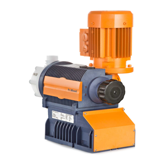
Diaphragm Motor-driven Metering Pump
Sigma/ 1 Basic Type S1Ba
EN
P_SI_0039
Please carefully read these operating instructions before use. · Do not discard.
The operator shall be liable for any damage caused by installation or operating errors.
The latest version of the operating instructions are available on our homepage.
Part no. 985911
Original Operating Instructions (2006/42/EC)
BA SI 075 09/17 EN
Advertisement
Table of Contents

Related Manuals for ProMinent Sigma/ 1 Basic S1Ba


Summary of Contents for ProMinent Sigma/ 1 Basic S1Ba
- Page 1 Operating instructions Diaphragm Motor-driven Metering Pump Sigma/ 1 Basic Type S1Ba P_SI_0039 Please carefully read these operating instructions before use. · Do not discard. The operator shall be liable for any damage caused by installation or operating errors. The latest version of the operating instructions are available on our homepage. Part no.
- Page 2 Supplemental directives Supplementary information Read the following supplementary information in its entirety! Should you already know this information, you will benefit more from referring to the operating instructions. The following are highlighted separately in the document: Enumerated lists Fig. 1: Please read! Operating guidelines ð...
-
Page 3: Table Of Contents
Table of contents Table of contents Identity code..................5 Safety chapter................. 7 2.1 Safety information for ATEX designs........11 Storage, Transport and Unpacking..........19 Overview of equipment and control elements....... 20 Functional description..............22 5.1 Pump..................22 5.2 Liquid end................22 5.3 Integral relief valve.............. - Page 4 Table of contents Declaration of Incorporation for Machinery........87 Declaration of Conformity for Machinery ATEX......88 Declaration of Incorporation for Machinery........89 Index....................90...
-
Page 5: Identity Code
Union nut and PVDF insert Union nut and SS insert Union nut and PVDF hose nozzle Union nut and SS hose nozzle Union nut and SS welding sleeve Design with ProMinent ® logo (standard) without ProMinent ® logo Physiological safety with FDA No. - Page 6 Identity code S1Ba Sigma 1 Basic Type Left liquid end Electric power supply Connection data - see motor nameplate Without gear motor No motor, with C 42 flange (NEMA) No motor, with B 5, size 56 (DIN) Degree of protection IP 55 (standard) Exe design ATEX-T3 *** Exd design ATEX-T4 ***...
-
Page 7: Safety Chapter
Observe the general limitations with regard to viscosity limits, chem‐ ical resistance and density - see also the ProMinent Resistance List (in the Product Catalogue or at www.prominent.com)! All other uses or modifications are prohibited. - Page 8 Safety chapter The pump is not intended for the metering of gaseous media and solids. The pump is not intended for the metering of explosive substances and mixtures. The pump is not intended for unprotected use outdoors. The pump is only intended for industrial use. Only allow trained and authorised personnel to operate the pump - see the following table.
- Page 9 Service The Service department refers to service technicians, who have received proven training and have been authorised by ProMinent to work on the system. Safety information WARNING!
- Page 10 – Take into account the resistance of the wetted mate‐ rials and the ProMinent Resistance List when selecting the feed chemical - see the ProMinent Product Catalogue or visit ProMinent. WARNING! Danger of injury to personnel and material damage The pump must only be opened at those points required to be opened by these operating instructions.
-
Page 11: Safety Information For Atex Designs
Safety chapter Protective equipment May only be removed by*: Motor terminal box cover Electrical technician, ATEX elec‐ trical technician, Service Protective cowling over the motor Service Power end front cover Service * Only if required by the operating instructions and if the mains cable remains disconnected from the mains voltage. - Page 12 Safety chapter Qualification of personnel Task Qualification Planning the hydraulic installation ATEX qualified person, ATEX elec‐ trical technician Electrical installation ATEX electrical technician Start up Skilled ATEX technician; Checking the electrical installation: Recognised competent person Maintenance, repair ATEX qualified person, ATEX elec‐ trical technician Troubleshooting Qualified ATEX technician or ATEX...
- Page 13 Safety chapter To carry out explosion hazard inspections the competent person must have: Completed a relevant course of study or Have a comparable technical qualification or Another technical qualification combined with long-term experience of safety technology. Make sure that the person is familiar with the relevant body of standards and regulations and has worked in the field for at least one year.
- Page 14 Safety chapter WARNING! ATEX pumps and flammable media Only with material versions PP_, PV_ and PC_: The igni‐ tion temperature is reduced significantly below the igni‐ tion temperature at atmospheric pressure due to com‐ pression with the discharge stroke of the possibly ignitable vapour-air mixture.
- Page 15 Safety chapter WARNING! The following applies in areas at risk from explosion: – Note the details of the type examination certificate PTB 00 ATEX 2048 X for the Namur sensor NJ1.5-8GM-N as well. WARNING! ATEX pumps in areas at risk from explosion –...
- Page 16 Other anomalies WARNING! Stop the pump immediately in the event of any anoma‐ lies when inspecting the pump and rectify them immedi‐ ately. ProMinent Service may be needed if required. Maintenance Interval Maintenance work After 18,000 operating hours or 23,500 oper‐...
- Page 17 Safety chapter Power end and motor – ATEX Data Value Unit Ambient temperature during operation: -10 ... +40 °C Liquid end - ATEX Data Value Unit Max. temperature, long-term at max. oper‐ 90 °C ating pressure Minimum temperature -10 °C Installation height Data Value Unit...
- Page 18 Safety chapter Fit the motor correctly on the flange (qualified personnel). WARNING! EX is relevant in an area at risk from explosion! As you have converted an "incomplete machine" into a complete machine, you must perform a conformity assessment, risk assess‐ ment, create an EC Declaration of Conformity, fit a company name‐...
-
Page 19: Storage, Transport And Unpacking
The "Decontamination Declaration Form" can be found at www.prominent.com. CAUTION! Danger of material damage The device can be damaged by incorrect or improper storage or transportation! –... -
Page 20: Overview Of Equipment And Control Elements
Overview of equipment and control elements Overview of equipment and control elements P_SI_0017_SW Fig. 3: Overview of equipment and control elements S1Ba Drive motor Drive unit Stroke length adjustment knob Liquid end with relief valve Diaphragm rupture sensor P_SI_0088_SW Fig. 4: Sigma control elements Relief valve Diaphragm rupture sensor (visual) - Page 21 Overview of equipment and control elements P_SI_0096_SW Fig. 5: Adjusting the stroke length 100 % = 2 rotations 50 % = 1 rotation 1 % = 1 scale mark on stroke adjustment dial PG11 P_SI_0036 Fig. 6: Front cover for version with pacing relay Pacing relay cable Supply voltage cable for pacing relay PCB...
-
Page 22: Functional Description
Functional description Functional description 5.1 Pump The metering pump is an oscillating diaphragm pump, the stroke length of which is adjustable. An electric motor drives the pump. 5.2 Liquid end The diaphragm (2) hermetically shuts off the pump volume of the dosing head (4) towards the outside. -
Page 23: Multi-Layer Safety Diaphragm
Functional description P_SI_0019 Fig. 8: Integral relief valve Spring, large Ball Rotary dial Spring, small Hose connection 5.4 Multi-layer safety diaphragm With visual diaphragm rupture sensors, in the event of a diaphragm rup‐ ture, the lowered red cylinder (6) springs forward beneath the transparent cover (7) so that it then becomes clearly visible - see Fig. -
Page 24: Assembly
Assembly Assembly Compare the dimensions on the dimension sheet with those of the pump. Install the motor - with designs without motor Select a suitable motor - it must correspond to the data for one of the motors from the "Motor data" table - see Chapter "Technical data". - Page 25 Assembly Tab. 1: Sigma Size Motor flange B 14/105 56C/138 1.14” B 14/105 B 14/105 52.5 B 5/140 * (26) Dimensions in mm - unless otherwise indicated. * Motor is fitted directly onto the motor flange without intermediate flange and claw coupling. Base WARNING! The pump can break through the base or slide off it...
- Page 26 Assembly Discharge valve Dosing head Suction valve Ensure there is sufficient free space (f) around the dosing head as well as the suction and discharge valve so that maintenance and repair work can be carried out on these components. P_MOZ_0017_SW Fig.
-
Page 27: Installation, Hydraulic
Installation, hydraulic Installation, hydraulic CAUTION! Danger of injury to personnel and material damage Disregarding the technical data during installation can lead to personal injuries or damage to property. – Observe the technical data - refer to the "Technical Data" chapter and, where applicable, the operating instructions for the accessories. - Page 28 They seal the connections between P_SI_0021 grooved pump valves and the grooved inserts from ProMinent - see Fig. 15. Fig. 15: Moulded composite seals with corrugated insert –...
- Page 29 Installation, hydraulic CAUTION! Warning of backflow Liquid ends, foot valves, back pressure valves, relief valves or spring-loaded injection valves do not constitute absolutely leak-tight sealing elements. – Use a shut-off valve, a solenoid valve or a vacuum breaker for this purpose. P_SI_0022 Fig.
- Page 30 Installation, hydraulic CAUTION! Danger of the integral relief valve failing The integral relief valve no longer operates reliably with feed chemicals having a viscosity of greater than 200 mPa s. – Only use the integral relief valve with feed chemicals having a viscosity up to 200 mPa s.
-
Page 31: Basic Installation Notes
Installation, hydraulic 7.1 Basic installation notes Safety notes CAUTION! Danger resulting from rupturing hydraulic components Hydraulic components can rupture if the maximum per‐ missible operating pressure is exceeded. – Never allow the metering pump to run against a closed shut-off device. –... -
Page 32: Installation, Electrical
Installation, electrical Installation, electrical CAUTION! Danger of injury to personnel and material damage Disregarding the technical data during installation can lead to personal injuries or damage to property. – Observe the technical data - refer to the "Technical Data" chapter and, where applicable, the operating instructions for the accessories. - Page 33 Never change the “Motor voltage” and “Cycle frequency” parameters with motor designs with integral frequency converter. The parameters on delivery from ProMinent do not cor‐ respond to the motor manufacturer’s factory settings. If other parameters are to be changed, then we recom‐...
- Page 34 Installation, electrical Motor WARNING! ATEX pumps in areas at risk from explosion – Use a suitable motor protection switch to protect power end motors. Use motor protection approved for this application with Ex"e" motors. (Protection against warming caused by overloading) –...
- Page 35 For further information on the motor with identity – code specification "S", refer to our website www.prominent.com. Motor data sheets can be requested for all other motors. – With motors other than those with identity code specifications "S", "M"...
- Page 36 Installation, electrical CAUTION! Only operate stroke length actuators / control drives when the pump is running. Otherwise they will become damaged. Diaphragm rupture sensor (optional) WARNING! Danger of electric shock In the event of a defect, there is a danger of electric shock if conductive feed chemicals are present.
- Page 37 Installation, electrical WARNING! The following applies in areas at risk from explosion: – Note the details of the type examination certificate PTB 00 ATEX 2048 X for the Namur sensor NJ1.5-8GM-N as well. Pacing relay (identity code specification "Stroke sensor": 2) Install the cable which originates from the pacing relay - see the figure in the chapter entitled "Overview of equipment and control elements": Cable A, left.
- Page 38 Installation, electrical Earthing lines Connect the electrical components of the entire installation supplied cleanly and permanently to an electrically clean earthing point, e.g. with an earthing bar on site - see earthing diagrams in the appendix. Potential equalisation line (prescribed in The entire installation supplied is provided ex works with the necessary the area at risk from explosion) potential equalisation lines.
-
Page 39: Start Up
Start up Start up Safety information WARNING! ATEX pumps in areas at risk from explosion – Make sure that a suitably competent person checks whether the appropriate installation information from the "Installation " chapter has been implemented correctly. – Make sure that a "recognised competent person" checks the electrical installation and in particular the intrinsically safe power circuits. - Page 40 Start up CAUTION! Feed chemical could escape – Check suction and discharge lines, and liquid end with valves for leak-tightness and tighten if neces‐ sary. – Check whether the necessary flushing pipes or bleed lines have been connected. CAUTION! Liquid end may be damaged –...
- Page 41 Start up ATEX only: Check the temperature of the Measure the surface temperature at maximum load. Additional information gear – refer to the operating instructions for the gear. Avoid particles The valves may no longer close properly with feed chemicals with a particle size of greater than 0.3 mm. Install a suitable filter in the suction line.
- Page 42 Start up When operating the integral relief valve close to the opening pressure, a minimal overflow into the overflow line can occur. Adjusting the stroke length Only adjust the stroke length when the pump is running. This is easier and also better for the pump. P_SI_0096_SW Fig.
-
Page 43: During Operation
During operation During operation WARNING! Fire hazard with flammable media Only with flammable media: They can be ignited by oxygen. – The pump may not work if there is a mixture of feed chemical with oxygen in the liquid end. A specialist may need to take appropriate actions (using inert gas, ...). -
Page 44: Maintenance
Maintenance Maintenance Safety information WARNING! ATEX pumps in areas at risk from explosion – Carry out a general check to ensure that the system is working properly, particularly the power end and bearings, by regularly monitoring it (for leaks, noises, temperatures, smell, etc.). –... - Page 45 Maintenance WARNING! It is mandatory that you read the safety information and specifications in the "Storage, Transport and Unpacking" chapter prior to shipping the pump. WARNING! Risk of injury from the fan impeller The fan impeller beneath motor's fan cowling can cause severe injuries while it is turning.
- Page 46 Maintenance WARNING! In the area at risk from explosion: stop the pump imme‐ diately and rectify these anomalies. ProMinent Service may be needed if required. Standard liquid ends: Under heavy loading (e.g. continuous operation) shorter maintenance intervals are recommended than those given.
- Page 47 Maintenance When using abrasive feed chemicals, the diaphragm service life is reduced. In these cases, more frequent checking of the diaphragm is rec‐ ommended. Tightening torques Data Value Unit Tightening torques for dosing head 4.5 ... 5.0 Nm screws: Liquid ends with integral relief valve WARNING! Warning of eye injuries When opening the relief valve, a spring under high ten‐...
-
Page 48: Carrying Out Repairs
Carrying out repairs Carrying out repairs Safety information WARNING! ATEX pumps in areas at risk from explosion – Generally check the proper functioning of the system, particularly of the power end and bearings, by regular monitoring (for leaks, noises, tempera‐ tures, smell .. -
Page 49: Cleaning Valves
Carrying out repairs 12.1 Cleaning valves Unsuitable spare parts for the valves may lead to prob‐ lems for the pumps. – Only use new components that are especially adapted to fit your valve (both in terms of shape and chemical resistance). Use the correct spare parts kits. -
Page 50: Replacing The Diaphragm
Carrying out repairs 12.2 Replacing the diaphragm Third-party spare parts for the pumps may lead to prob‐ lems when pumping. – Only use original spare parts. Use the correct spare parts kits. In the event of – doubt, refer to the exploded views and ordering information in the appendix. - Page 51 Should this not work, remove dirt or swarf out of the thread and screw the diaphragm correctly onto the drive axle this time. ð If this is still unsuccessful, contact ProMinent-ProMaqua cus‐ tomer service. Place the dosing head with the screws onto the diaphragm - the suction connector should be pointing downwards in the pump's fit‐...
- Page 52 Carrying out repairs Check whether it can move freely in the hole. Refit the clean diaphragm rupture sensor with the clean piston. Test the diaphragm rupture sensor. Optical diaphragm rupture sensor Unscrew the transparent cover from the diaphragm rupture sensor. Press the red cylinder into the diaphragm rupture sensor until it engages.
- Page 53 Carrying out repairs P_SI_0038 Fig. 24: Cross-section through the liquid end Suction valve Diaphragm Discharge valve Dosing head Backplate 13 Safety diaphragm Tightening torques Data Value Unit Tightening torques for dosing head 4.5 ... 5.0 Nm screws:...
-
Page 54: Troubleshooting
Troubleshooting Troubleshooting Safety information WARNING! ATEX pumps in areas at risk from explosion – Generally ensure that the parts are working properly (no leaks, unusual noises, high temperatures, unusual smell ...) especially the power end/drive and the bearings. – Do not allow the pump to heat up because of a lack of oil! With lubricated metering pumps, regularly check for the presence of lubricant, for example by checking... - Page 55 Troubleshooting WARNING! Only motors with a frequency converter: Danger of elec‐ tric shock The danger of electric shock remains for 3 minutes after the mains voltage has been switched off on conducting parts of the motor with an integrated frequency converter and on the lines themselves.
- Page 56 Rectify any constriction of the dis‐ Technical per‐ ously constricted. charge line. sonnel All other faults. Other causes. Call ProMinent Service. ® * If necessary use the cross-section drawing of the integral relief valve in the "Functional Description" chapter. WARNING! Warning of eye injuries When opening the relief valve, a spring under high ten‐...
-
Page 57: Decommissioning
Decommissioning Decommissioning Decommissioning WARNING! Fire hazard with flammable media Only with flammable media: They can be ignited by oxygen. – The pump may not work if there is a mixture of feed chemical with oxygen in the liquid end. A specialist may need to take appropriate actions (using inert gas, ...). - Page 58 Decommissioning CAUTION! Warning of feed chemical spraying around Feed chemical can spray out of the hydraulic compo‐ nents if they are manipulated or opened due to pressure in the liquid end and adjacent parts of the system. – Disconnect the pump from the mains power supply and ensure that it cannot be switched on again by unauthorised persons.
-
Page 59: Technical Data
Technical data Technical data Only with "M - modified" design: WARNING! Risk of personal injuries Please observe the ”Supplement for modified version“ at the end of the chapter! It replaces and supplements the technical data! 15.1 Performance data S1Ba with 50 Hz operation Type Minimum pump capacity at maximum Maximum... -
Page 60: Viscosity
Technical data S1Ba with 60 Hz operation Type Minimum pump capacity at maximum back pres‐ Maximum Suction lift Permissible Connector sure stroke priming size rate pressure, suction side Strokes/mi m WS R"-DN 12017 PVT 3/4" - 10 12017 SST 3/4" - 10 12035 PVT 11.1 3/4"... -
Page 61: Shipping Weight
Technical data 15.3 Shipping weight Types Material version Shipping weight 12017 ... 07065 PVT, TTT 07042 ... 04129 PVT, TTT 15.4 Wetted materials Material ver‐ Liquid end Suction/pres‐ Seals* / ball Balls Springs Integral relief sion sure connector seat valve PVDF PVDF PTFE/PTFE... -
Page 62: Air Humidity
Technical data SST liquid end Data Value Unit Max. temperature, long-term at max. oper‐ 90 °C ating pressure Max. temperature, for 15 min at max. 2 bar 120 °C* Minimum temperature -10 °C * not in areas at risk from explosion 15.5.3 Air humidity Air humidity... -
Page 63: Stroke Actuator
For further information on the motor with identity – code specification "S", refer to our website www.prominent.com. Motor data sheets can be requested for all other motors. With motors other than those with identity code –... -
Page 64: Stroke Sensor "Sigma
Technical data The diaphragm rupture sensor is an N/C. – For safety reasons we recommend connecting to a protective low voltage, e.g. in accordance with EN 60335-1 (SELV). The cable can be connected as required. – a) Namur sensor (for identity code specifi‐ cation "Displacement body“: A) Install the sensor according to the chapter "Installation, electrical". -
Page 65: Relay
Technical data b) Namur sensor (identity code specifica‐ tion "Stroke sensor": 3) Install the sensor according to the chapter "Installation, electrical". Refer to its documentation. Sensor name: NJ1.5-8GM-N. 5–25 V DC, in accordance with Namur or DIN 60947-5-6, potential-free design. Data Value Unit Nominal voltage *... - Page 66 Technical data Spare parts With a modified version, it is absolutely necessary to specify the details of the serial number requesting and ordering the spare and replacement parts.
-
Page 67: Diagrams For Setting The Capacity
Diagrams for Setting the Capacity Diagrams for Setting the Capacity S1Ba (50 Hz) S1Ba (50 Hz) C [l/h] C [l/h] 70.0 60.0 10050 60.0 07065 50.0 12035 * 10044 12017 * 50.0 10022 40.0 40.0 30.0 30.0 20.0 20.0 10.0 10.0 S [%] S [%]... - Page 68 Diagrams for Setting the Capacity S1Ba (60Hz) S1Ba (60Hz) C [l/h] C [l/h] 90.0 70.0 80.0 60.0 10050 07065 70.0 10044 12035 * 10022 50.0 60.0 12017 * 40.0 50.0 40.0 30.0 30.0 20.0 20.0 10.0 10.0 S [%] S [%] C [l/h] C [l/h] 90.0...
-
Page 69: Dimensional Drawings
Dimensional drawings Dimensional drawings Compare the dimensions on the dimension sheet – and pump. All dimensions are in mm. – Dimensional drawing for Sigma/ 1, S1Ba max.40 P_SI_0033 Fig. 27: Dimensional drawing of Sigma/ 1, S1Ba - Drawing is not strictly binding. Hose nozzle relief valve d16 S with thread DIN ISO 228-G3/4 A Tab. - Page 70 Dimensional drawings Type Connector Sigma 10022, 10044, DN10 G 3/4 A 91 07065 SST-relief valve- A/sv-a Sigma 07042, 04085, DN15 G 1 A 04120 PVT Sigma 07042, 04085, DN15 G 1 A 04120 PVT-relief valve- A/sv-a Sigma 07042, 04085, DN15 G 1 A 04120 SST Sigma 07042, 04085,...
- Page 71 Dimensional drawings Dimensional drawing of Sigma/ 1, S1Ba, rotated P_SI_0155_SW Fig. 28: Dimensional drawing of Sigma/ 1, S1Ba, rotated - Drawing is not strictly binding. Hose nozzle relief valve d16 S with thread DIN ISO 228-G3/4 A Tab. 6: Dimensions in mm Type Connector Sigma 12017,12035,...
- Page 72 Dimensional drawings Type Connector Sigma 07042, 04085, DN15 G 1 A 04120 SST Sigma 07042, 04085, DN15 G 1 A 04120 SST-relief valve- A/sv-a Tab. 7: Dimensions in mm Standard motor Motor, controllable EExe motor Motor with fre‐ 1-phase motor quency converter Dimensional drawing of Sigma/ 1, S1Ba, motor flange, actuator...
- Page 73 Dimensional drawings Dimensional drawing of Sigma 1, S1Ba with EExde motor P_SI_0156_SW Fig. 30: Dimensional drawing of Sigma/ 1, S1Ba, with EExde motor - Drawing is not strictly binding. Tab. 9: Dimensions in mm Type Connector Sigma 12017,12035, DN10 G 3/4 A 70 10050 PVT Sigma 12017,12035, DN10...
- Page 74 Dimensional drawings Type Connector Sigma 07042, 04084, DN15 G 1 A 04120 PVT-relief valve- A/sv-a Sigma 07042, 04084, DN15 G 1 A 04120 SST Sigma 07042, 04084, DN15 G 1 A 04120 SST-relief valve- A/sv-a...
-
Page 75: Potential Equalisation Drawings For Sigma Basic Type
Potential equalisation drawings for Sigma Basic Type Potential equalisation drawings for Sigma Basic Type P_SI_0169_SW Fig. 31: Potential equalisation drawing for Sigma S1Ba Potential equalisation of motor Potential equalisation of motor flange Potential equalisation of liquid end Positions 1, 2 and 3 must be connected to a protective earth cable. -
Page 76: Motor Data Sheet Standard Motor
This information is supplied without liability. Les données techniques correspondent au descriptif du fabricant des moteurs. Les données techniques des moteurs similaires chez d’ autres fabricants varient très peu. Données sont d’ ordre général. ProMinent Dosiertechnik GmbH . 69123 Heidelberg . Germany No. MD-1018432, 1018433, 1018455 Datum/Date April 2011... -
Page 77: Exploded Drawings Sigma/ 1
Exploded drawings Sigma/ 1 Exploded drawings Sigma/ 1 Liquid end Sigma/ 1 050 and 065 PVT P_SI_0024 Fig. 32: Liquid end Sigma/ 1 050 and 065 PVT Pos. Description Type 12035, 12017, Type 07065, 10044, 10050 10022 Spring Ball Ball seat Diaphragm rupture sensor, visual 1033323 1033323... - Page 78 Exploded drawings Sigma/ 1 Liquid end Sigma/ 1 120 PVT P_SI_0024 Fig. 33: Liquid end Sigma/ 1 120 PVT Pos. Description Type 04084, 04120, 07042 Spring Ball Ball seat Diaphragm rupture sensor, visual 1033323 Valve 792517* Multi-layer diaphragm 1035828* * The items listed are included in the spare parts kit. ** Special accessories (not included in the spare parts kit). Tech‐ nical changes reserved.
- Page 79 Exploded drawings Sigma/ 1 Sigma/ 1 PVT relief valve-A P_SI_0086_SW Fig. 34: Sigma/ 1 PVT relief valve-A Pos. Description Type 12035, Type 10050, Type 07065, Type 04084, 12017 10044, 10022 07042 04120 Relief valve, complete 12 bar PVA 1018572 Relief valve, complete 10 bar PVA 1018947 Relief valve, complete 7 bar PVA 740811...
- Page 80 Exploded drawings Sigma/ 1 Liquid end Sigma/ 1 050 and 065 SST P_SI_0025_SW Fig. 35: Liquid end Sigma/ 1 050 and 065 SST Pos. Description Type 12035, 12017, Type 07065, 10044, 10050 10022 Spring Ball Ball seat Diaphragm rupture sensor, visual 1033323 1033323 Valve...
- Page 81 Exploded drawings Sigma/ 1 Liquid end Sigma/ 1 120 SST P_SI_0025_SW Fig. 36: Liquid end Sigma/ 1 120 SST Pos. Description Type 04084, 04120, 07042 Spring Ball Ball seat Diaphragm rupture sensor, visual 1033323 Valve 809404 Multi-layer diaphragm 1035828* * The items listed are included in the spare parts kit. ** Special accessories (not included in the spare parts kit). Tech‐ nical changes reserved.
- Page 82 Exploded drawings Sigma/ 1 Sigma/ 1 SST relief valve-A P_SI_0087 Fig. 37: Sigma/ 1 SST relief valve-A Pos. Description Type 12035, Type 10050, Type 07065, Type 04084, 12017 10044, 10022 07042 04120 Relief valve, complete 12 bar SSA 1005625 Relief valve, complete 10 bar SSA 1018573 Relief valve, complete 7 bar SSA 740815...
- Page 83 Exploded drawings Sigma/ 1 Pos. Type Quantity Article Order no. 1.000 Liquid end Sigma 1 - 50 SSTH 1036541 1.000 Liquid end Sigma 1 - 65 SSTH 1036542 1.000 Liquid end Sigma 1 - 120 SSTH 1036543 1.000 Hyg.dos. head, complete 96.0 x 42.0 LK80 1035627 1.000 Hyg.
-
Page 84: Wear Parts For Sigma/ 1
Wear parts for Sigma/ 1 Wear parts for Sigma/ 1 21.1 Standard Spare parts kits PVT (liquid ends) Spare parts kit Types 12017, 12035, Types 10022, 10044, Types 07042, 04084, 10050 07065 04120 FM 50 - DN10 1035964 FM 65 - DN10 1035967 FM 120 - DN15 1035961... - Page 85 Wear parts for Sigma/ 1 Tab. 10: Scope of delivery with PVT material version 1 x diaphragm, 2 x valve balls, 1 x suction valve complete, 1 x discharge valve complete 1 x elastomer sealing set (EPDM) 2 x ball seat housings, 2 x ball seat discs, 4 x composite seals 1x seal washer (for bleed valve or relief valve) Tab.
-
Page 86: Declaration Of Conformity For Machinery
Appendix I, No. 1.5.1 of the Machinery Directive 2006/42/EC EMC Directive (2014/30/EU) Harmonised standards applied, in EN ISO 12100:2010 particular: EN 809:1998 + A1:2009 + AC:2010 EN 61000-6-2:2005 + AC:2005 EN 61000-6-4:2007 + A1:2011 + AC:2012 Date: 20.04.2016 You can download the Declaration of Conformity at www.prominent.com. -
Page 87: Declaration Of Incorporation For Machinery
Compliance with the protection targets of the Low Voltage Directive 2014/35/EU according to Appendix I, No. 1.5.1 of the Machinery Directive 2006/42/EC Harmonised standards applied, in EN ISO 12100:2010 particular: EN 809:1998 + A1:2009 + AC:2010 Date: 20.04.2016 You can download the Declaration of Conformity at www.prominent.com. -
Page 88: Declaration Of Conformity For Machinery Atex
* “Special conditions” - refer also to the chapter entitled “Special conditions for ATEX”. You can download the Declaration of Conformity at www.prominent.com. The Declarations of Conformity, the EC type-examination certificates and the operating instructions for the individual components are also enclosed... -
Page 89: Declaration Of Incorporation For Machinery
II 2G IIC T4 X X: max. medium temperature 90 °C Ambient temperature -10 °C ... + 40 °C Assess the ignition risk when combining the pump and motor. Date: 20.04.2016 You can download the Declaration of Conformity at www.prominent.com. -
Page 90: Index
Index Index Information in the event of an emergency ..10 Installation ....... 27 Actuator . - Page 91 Index Scope of delivery ......19 Serial numbers ....86, 87, 88, 89 Shipping weight .
- Page 92 ProMinent GmbH Im Schuhmachergewann 5-11 69123 Heidelberg Germany Telephone: +49 6221 842-0 Fax: +49 6221 842-419 Email: info@prominent.com Internet: www.prominent.com Heidelberg, 4, en_GB © 2011...
Need help?
Do you have a question about the Sigma/ 1 Basic S1Ba and is the answer not in the manual?
Questions and answers