Table of Contents
Advertisement
Quick Links
Operating instructions
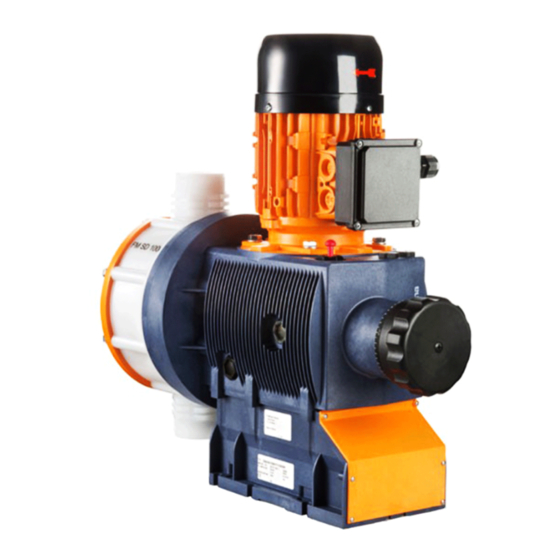
Piston Metering Pump
Sigma / 2 Basic Type SBKa
P_SI_0135_SW
Please carefully read these operating instructions before use! · Do not discard!
The operator shall be liable for any damage caused by installation or operating errors!
Technical changes reserved.
Part no. 984863
Original operating instructions (2006/42/EC)
BA SI 059 11/13 EN
Advertisement
Table of Contents

Related Manuals for ProMinent Sigma / 2 Basic Type SBKa


Summary of Contents for ProMinent Sigma / 2 Basic Type SBKa
- Page 1 Operating instructions Piston Metering Pump Sigma / 2 Basic Type SBKa P_SI_0135_SW Please carefully read these operating instructions before use! · Do not discard! The operator shall be liable for any damage caused by installation or operating errors! Technical changes reserved.
- Page 2 Supplemental instructions Supplementary information Read the following supplementary information in its entirety! Should you already know this information, you will benefit more from referring to the operating instructions. The following are highlighted separately in the document: Enumerated lists Fig. 1: Please read! Operating guidelines ð...
-
Page 3: Table Of Contents
Table of contents Table of contents Identity code..................4 Safety chapter................. 6 Storage, transport and unpacking..........11 Overview of equipment and control elements....... 12 Functional description..............14 5.1 Drive unit................14 5.2 Liquid End................14 Assembly..................15 Installation..................17 7.1 Installation, hydraulic............. 17 7.2 Installation, electrical............. -
Page 4: Identity Code
Piston (oxide ceramic) Dosing head design no valve springs with 2 valve springs, Hastelloy C; 0.1 bar Hydraulic connector Standard threaded connector (in line with technical data) Design With ProMinent logo (standard) ® Without ProMinent ® logo Modified* * order-related design, refer to... - Page 5 Identity code SBKa Sigma 2 Basic Type With servomotor, 115 V, 50/60 Hz With control motor 0...20 mA 230 V, 50/60 Hz With control motor 4...20 mA 230 V, 50/60 Hz With control motor 0...20 mA 115 V, 50/60 Hz With control motor 4...20 mA 115 V, 50/60 Hz...
-
Page 6: Safety Chapter
Safety chapter Safety chapter CAUTION! These operating instructions include notes and quotes from German guidelines relating to the system operator's scope of responsibility. This information does not discharge the oper‐ ator from his responsibility as an operator and is intended only to remind him or make him aware of specific problem areas. - Page 7 Safety chapter Observe the general limitations with regard to viscosity limits, chem‐ ical resistance and density - see also ProMinent Resistance List (in the Product Catalogue or at www.prominent.com/en/downloads)! All other uses or modifications are prohibited. Never operate pumps without the relevant nameplate (and the respec‐...
- Page 8 Service Customer Service department refers to service technicians, who have received proven training and have been authorised by ProMinent or Pro‐ Maqua to work on the system. Safety notes WARNING! –...
- Page 9 An unsuitable feed chemical can damage the parts of the pump that come into contact with the chemical. – Take into account the resistance of the wetted materials when selecting the feed chemical - see the ProMinent product catalogue or visit www.prominent.com/en/down‐ loads. CAUTION!
- Page 10 Safety chapter Drive front cover Motor fan cowling Terminal box cover, motor Protective cover - see figure. P_SI_0146_SW Fig. 3: Protective cover, two-section (*) Only remove them when the operating instructions request you to do so. Information in the event of an emergency In the event of an electrical accident, disconnect the mains cable from the mains or press the emergency cut-off switch fitted on the side of the system!
-
Page 11: Storage, Transport And Unpacking
The "Decontamination Declaration Form" can be found at www.prominent.com/en/downloads. WARNING! Slings can tear ProMinent only supplies non-reusable slings. These can tear with repeated use. – Only use the slings once. CAUTION! Danger of material damage... -
Page 12: Overview Of Equipment And Control Elements
Overview of equipment and control elements Overview of equipment and control elements P_SI_0140_SW Fig. 4: Overview of equipment and control elements SBKa Liquid end Drive motor Gear bleeding plug Drive unit Stroke length adjustment knob 75 % 50 % Fig. 5: Adjusting the stroke length 100 % = 10 rotations 10 % = 1 rotation 0.2 % = 1 scale mark on stroke adjustment dial... - Page 13 Overview of equipment and control elements PG11 P_SI_0036 Fig. 6: Front cover for version with pacing relay Pacing relay cable Supply voltage cable for pacing relay PCB...
-
Page 14: Functional Description
Functional description Functional description 5.1 Drive unit The metering pump is an oscillating diaphragm pump, the stroke length of which can be adjusted. An electric motor drives the pump. 5.2 Liquid End The heart of the liquid end is a highly resistant piston (4) made from coated stainless steel. -
Page 15: Assembly
Assembly Assembly Compare the dimensions on the dimension sheet and pump. Base WARNING! Danger of electric shock If water or other electrically conducting liquids penetrate into the drive housing, in any other manner than via the pump's suction connection, an electric shock may occur. –... - Page 16 Assembly Liquid end alignment Capacity too low The liquid end valves cannot close correctly if they are not upright. Ensure that the discharge valve is upright. – Fastening Capacity too low Vibrations can disrupt the liquid end valves. Secure the metering pump so that no vibrations can –...
-
Page 17: Installation
Installation Installation CAUTION! Danger of injury to personnel and material damage Disregarding the technical data when installing may lead to personal injuries or damage to property. – Observe the technical data- refer to chapter "Technical Data" and, where applicable, the operating instructions of the accessories. - Page 18 Installation CAUTION! Warning of feed chemical spraying around PTFE seals, which have already been used / compressed, can no longer reliably seal a hydraulic connection. – New, unused PTFE seals must always be used. CAUTION! Suction problems possible The valves may no longer close properly using feed chemi‐ cals with a particle size of greater than 0.3 mm.
- Page 19 Installation Standard installation P_MAZ_0001_SW Fig. 12: Standard installation Main line Storage tank Symbols for the components Symbol Explanation Symbol Explanation Injection valve Multifunctional valve Manometer Relief valve (alterna‐ Metering pump tively a multifunction valve can be used) Level switch Foot valve with filter meshes Route the leakage liquid drainage line CAUTION!
-
Page 20: Installation, Electrical
This can either be in the form of a decla‐ ration of conformity from the supplier (ProMinent) for the entire unit or, with the supply of individual components, with the operator's explosion protection document. - Page 21 Installation WARNING! Danger of electric shock A mains voltage may exist inside the motor or electrical ancil‐ laries. – If the housing of the motor or electrical ancillaries has been damaged, you must disconnect it from the mains immediately. Only return the pump to service after an authorised repair.
- Page 22 Installation Install a motor protection switch, as the motors have no fuse. Install an emergency cut-off switch or include the motor in the emer‐ gency cut-off management plan for the system. Only connect the motor to the voltage supply using a suitable cable. Key motor data can be found on the nameplate.
- Page 23 Installation Install the power supply cable to the pacing relay PCB - see the figure in the chapter entitled "Overview of equipment and control elements": Cable B, right. CAUTION! Warning of overload If the current through the relay becomes too high, it can be destroyed by heating.
-
Page 24: Start Up
Start up Start up Safety notes WARNING! EX pump in area at risk from explosion – A qualified or skilled operative should check whether the installation information from the "Installation" chapter has been implemented correctly. – Check whether the installation instructions from the "Installation"... - Page 25 Start up This will rule out the pump losing oil and suffering damage. Checking the direction of rotation When commissioning the unit, check whether the drive motor is rotating correctly - check this against the arrow on the motor housing or the dia‐ gram in the chapter entitled "Electrical Installation."...
-
Page 26: Maintenance
– These measures constitute the minimum protective measurements stipulated by ProMinent. It is the duty of the operator to eliminate any other dangers identified by appropriate measures. WARNING! It is mandatory that you read the safety information and specifications in the "Storage, Transport and Unpacking"... - Page 27 Maintenance WARNING! Risk of injury from the fan impeller The fan impeller beneath motor's fan cowling can cause severe injuries while it is turning. – The pump must only be connected to the mains voltage with the fan cowling closed. CAUTION! Warning of feed chemical spraying around Feed chemical can spray out of the hydraulic components if...
- Page 28 Maintenance (7 Nm) (7.5 Nm) P_SI_0148_SW Fig. 14: Liquid end tightening torques Dosing head screws Turret flange screws Interval Maintenance work Quarterly* Check the starting torque torques for the dosing head flange screws (1) (7 Nm) and the turret flange screws (2) (7.5 Nm).
- Page 29 Maintenance Changing the gear oil WARNING! Risk of burns due to hot gear oil The gear oil may become very hot when the pump is heavily loaded – When draining oil, avoid contact with the oil running out. Gear oil Gear oil Supplied quantity Part no.
-
Page 30: Repairs
Repairs Repairs Safety notes WARNING! EX pump in area at risk from explosion – Ensure correct operation in general, particularly of the power end and bearings, by regular monitoring (for leaks, noises, temperatures, smell ...). WARNING! It is mandatory that you read the safety information and specifications in the "Storage, Transport and Unpacking"... -
Page 31: Cleaning Double Ball Valves
Repairs Unsuitable spare parts for the valves may lead to problems for the pumps. Only use new components that are especially adapted to – fit your valve (both in terms of shape and chemical resistance). Use the correct spare parts kits. In case of doubt, refer –... -
Page 32: Changing The Piston
Repairs Fig. 16: Discharge valve (double ball valve). Cleaning a suction valve A suction valve is dismantled, cleaned and assembled in the same way as a discharge valve. Please note, however, that when assembling, the valve seat (3) must be aligned in the other direction. The fine machined side must point in the flow direction with all valve seats (3). - Page 33 Repairs P_SI_0145_SW Fig. 17: Cross-section through the liquid end Dosing head Piston Dosing head flange Flushing collar Guide ring Washer 16 Spring 20 V-sleeve packing 21 O-ring 23 FOI ring 24 Guide band 25 Dosing head flange screws 26 Liquid end retaining screws 27 Guide ring screws 31 Tube nozzles for leakage/flushing connector Repairing the liquid end...
- Page 34 Repairs Push the spring (16) and the washer (6) into the dosing head. CAUTION! The piston may be damaged – Do not damage the sealing lips of the V-sleeve packing (20). Push the V-sleeve packing (20) into the dosing head. The thicker ring comes last! Align the V-type rings with the open side towards the dosing head, as for the FOI ring (23), see Fig.
- Page 35 Repairs Attach the upper protective cover to the turret. If fitted: Connect the flushing tubes to the hose nozzles.
-
Page 36: Troubleshooting
Troubleshooting Troubleshooting Safety notes WARNING! EX pumps in areas at risk from explosion – Generally ensure proper operation (no leaks, unusual noises, high temperatures, unusual smell ...) especially with the power end and the bearings. – Do not allow the pump to heat up because of lack of oil. If oil is escaping, investigate the leak immediately and eliminate the cause. - Page 37 The use of untested third party parts can result in personnel injuries and material damage. – Only fit parts to metering pumps, which have been tested and recommended by ProMinent. CAUTION! Warning of feed chemical spraying around Feed chemical can spray out of the hydraulic components if they are manipulated or opened due to pressure in the liquid end and adjacent parts of the system.
-
Page 38: Decommissioning
Decommissioning Decommissioning Decommissioning WARNING! Danger of an electric shock When working on the motor or electrical auxiliary equipment, there is a danger of an electric shock. – Before working on the motor, take note of the safety instructions in its operating instructions! –... - Page 39 Decommissioning CAUTION! Danger of damage to the device The device can be damaged by incorrect and improper storage or transportation. – Take into account the information in the "Storage, Trans‐ port and Unpacking" chapter if the system is decommis‐ sioned for a temporary period. (Temporary) decommissioning Personnel: Technical personnel...
-
Page 40: Technical Data
Technical data Technical data Only for "M - modified" design: WARNING! Risk of personal injuries Please observe the ”Supplement for modified version“ at the end of the chapter! It replaces and supplements the technical data! 13.1 Performance data SBKa under 50 Hz operation Type Minimum pump capacity at maximum Maximum... -
Page 41: Shipping Weight
Technical data SBKa under 60 Hz operation Type Minimum pump capacity at maximum back pres‐ Maximum Suction lift Permissible Connector sure stroke priming size rate pressure, suction side Strokes/ m WS 32002 4660 23004 3335 10006 1450 14006 2030 10011 1450 13.1 05016... -
Page 42: Wetted Materials
Technical data Design Range Unit with appropriately laid 500 ... 1000 mPas out installation with appropriately laid > 1000 mPas out installation and advice from ProMinent 13.4 Wetted materials Liquid end Suction/pressure Seals / ball seat Balls Ball seat Piston connector... -
Page 43: Stroke Sensor "Sigma
Technical data Motor data sheets, special motors, special motor flanges, external fan, temperature monitoring Motor data sheets can be requested for more informa‐ – tion. For motors other than those with identity code specifica‐ – tions "S", "M" or "N": Pay special attention to the oper‐ ating instructions for the motors. -
Page 44: Gear Oil
Technical data 13.9 Gear oil Manufac‐ Name Viscosity Part no. Oil volume, turer class supplied volume, (ISO needed 3442) Mobil Mobil VG 460 1004542 1.0 l 0.5 l Gear 634 * or comparative gear oil 13.10 Sound pressure level Sound pressure level Sound pressure level LpA <... -
Page 45: Diagrams For Adjusting The Capacity
Diagrams for adjusting the capacity Diagrams for adjusting the capacity SBKa (50 Hz) SBKa (50 Hz) C [l/h] C [l/h] 01264 05016 02534 10006 02541 10011 04522 23004 04022 14006 07012 32002 S [%] S [%] C [l/h] C [l/h] 05016 01264 10006... -
Page 46: Dimensional Drawings
Dimensional drawings Dimensional drawings Dimensional drawing Sigma SBKa 33.5 61_01_101_00_39_73 Fig. 21: Dimensional drawing Sigma SBKa - dimensions in mm Type Liquid end 32002, 23004, 10006 FK 08 Rp 1/4 (DN8) 14006, 10011, 05016 FK 12.5 Rp 1/4 (DN8) 07012, 04522, 02534 FK 25 Rp 1/4 (DN8) 04022, 02541, 01264... -
Page 47: Exploded Drawing Sigma Piston Metering Pump
Exploded drawing Sigma piston metering pump Exploded drawing Sigma piston metering pump Liquid end P_SI_0137_SW Fig. 22: * The items listed are included in the spare parts kit. Optional accessories (not in the spare part kits) -
Page 48: Sigma/ 2 Piston Ordering Information
Sigma/ 2 piston ordering information Sigma/ 2 piston ordering information Spare parts kits normally include the wearing parts of a liquid end. Other locations where ordering information can be found: Exploded drawings, ProMinent product catalogue, ® www.prominent.com/en/downloads. Spare parts kits SST (liquid ends) -
Page 49: Ec Declaration Of Conformity For Machinery
In accordance with DIRECTIVE 2006/42/EC OF THE EUROPEAN PAR‐ LIAMENT AND OF THE COUNCIL, Appendix I, BASIC HEALTH AND SAFETY REQUIREMENTS, section 1.7.4.2. C. ProMinent Dosiertechnik GmbH Im Schuhmachergewann 5 - 11 D - 69123 Heidelberg, hereby declares that the product specified in the following, complies with... -
Page 50: Ec Declaration Of Conformity For Machinery Used In Areas At Risk Of Explosion
In accordance with DIRECTIVE 2006/42/EC OF THE EUROPEAN PAR‐ LIAMENT AND OF THE COUNCIL, Appendix I, BASIC HEALTH AND SAFETY REQUIREMENTS, section 1.7.4.2. C. ProMinent Dosiertechnik GmbH Im Schuhmachergewann 5 - 11 D - 69123 Heidelberg, hereby declares that the product specified in the following, complies with... - Page 52 ProMinent Dosiertechnik GmbH Im Schuhmachergewann 5-11 69123 Heidelberg Germany Telephone: +49 6221 842-0 Fax: +49 6221 842-612 email: info@prominent.com Internet: www.prominent.com 986266, 1, en_GB © 2011...
Need help?
Do you have a question about the Sigma / 2 Basic Type SBKa and is the answer not in the manual?
Questions and answers