Table of Contents
Advertisement
Quick Links
Operating instructions
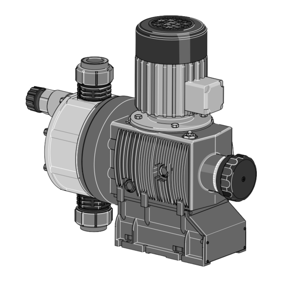
Diaphragm Motor-Driven Metering Pump
Sigma / 3 Basic Type S3Ba
P_SI_0075_SW
Please carefully read these operating instructions before use! · Do not discard!
The operator shall be liable for any damage caused by installation or operating errors!
Technical changes reserved.
Part no. 985905
Original operating instructions (2006/42/EC)
BA SI 064 01/14 EN
Advertisement
Table of Contents

Related Manuals for ProMinent Sigma/3 Basic S3Ba Series


Summary of Contents for ProMinent Sigma/3 Basic S3Ba Series
- Page 1 Operating instructions Diaphragm Motor-Driven Metering Pump Sigma / 3 Basic Type S3Ba P_SI_0075_SW Please carefully read these operating instructions before use! · Do not discard! The operator shall be liable for any damage caused by installation or operating errors! Technical changes reserved. Part no.
- Page 2 Supplemental instructions Supplementary information Read the following supplementary information in its entirety! Should you already know this information, you will benefit more from referring to the operating instructions. The following are highlighted separately in the document: Enumerated lists Fig. 1: Please read! Operating guidelines ð...
-
Page 3: Table Of Contents
Table of contents Table of contents Identity code..................4 Safety chapter................. 6 Storage, transport and unpacking..........11 Overview of equipment and control elements....... 12 Functional description..............14 5.1 Pump..................14 5.2 Liquid end................14 5.3 Integral relief valve..............14 5.4 Multi-layer safety diaphragm..........15 Assembly.................. -
Page 4: Identity Code
Union nut and PVDF insert Union nut and SS insert Union nut and PVDF tube nozzle Union nut and SS tube nozzle Union nut and SS welding sleeve Design With ProMinent logo ® Without ProMinent ® logo Physiological safety with FDA No. - Page 5 Identity code S3Ba Sigma 3 Basic Type Modified* * order-related design, refer to order paperwork for pump features Electric power supply Connection data - refer to nameplate on motor No motor, with B 5 flange, size 80 (DIN) No motor, with C 56 flange (NEMA) No motor, with B 5, size 71 (DIN) Degree of protection IP 55 (standard)
-
Page 6: Safety Chapter
Safety chapter Safety chapter CAUTION! These operating instructions include notes and quotes from German guidelines relating to the system operator's scope of responsibility. This information does not discharge the oper‐ ator from his responsibility as an operator and is intended only to remind him or make him aware of specific problem areas. - Page 7 Safety chapter Observe the general limitations with regard to viscosity limits, chem‐ ical resistance and density - see also ProMinent Resistance List (in the Product Catalogue or at www.prominent.com/en/downloads)! All other uses or modifications are prohibited. Never operate pumps without the relevant nameplate (and the respec‐...
- Page 8 Service Customer Service department refers to service technicians, who have received proven training and have been authorised by ProMinent or Pro‐ Maqua to work on the system. Safety notes WARNING! –...
- Page 9 An unsuitable feed chemical can damage the parts of the pump that come into contact with the chemical. – Take into account the resistance of the wetted materials when selecting the feed chemical - see the ProMinent product catalogue or visit www.prominent.com/en/down‐ loads. CAUTION!
- Page 10 Safety chapter Drive front cover Motor fan cowling Terminal box cover, motor Only remove them when the operating instructions request you to do so. Information in the event of an emergency In the event of an electrical accident, disconnect the mains cable from the mains or press the emergency cut-off switch fitted on the side of the system! If feed chemical escapes, also depressurise the hydraulic system around...
-
Page 11: Storage, Transport And Unpacking
You can find the "Decontamination Declaration" form under www.prominent.com/en/downloads or on the CD. CAUTION! Danger of material damage The device can be damaged by incorrect or improper storage or transportation! –... -
Page 12: Overview Of Equipment And Control Elements
Overview of equipment and control elements Overview of equipment and control elements P_SI_0070_SW Fig. 3: Overview of equipment and control elements S3Ba Drive motor Drive unit Stroke length adjustment knob Liquid end with relief valve Diaphragm rupture sensor P_SI_0088_SW Fig. 4: Sigma control elements Relief valve Diaphragm rupture sensor (visual) - Page 13 Overview of equipment and control elements P_SI_0095_SW Fig. 5: Adjusting the stroke length 100 % = 4 rotations 25 % = 1 rotation 0.5 % = 1 scale mark on stroke adjustment dial PG11 P_SI_0036 Fig. 6: Front cover for version with pacing relay Pacing relay cable Supply voltage cable for pacing relay PCB...
-
Page 14: Functional Description
Functional description Functional description 5.1 Pump The metering pump is an oscillating diaphragm pump, the stroke length of which is adjustable. An electric motor drives the pump. 5.2 Liquid end The diaphragm (2) hermetically shuts off the pump volume of the dosing head (4) towards the outside. -
Page 15: Multi-Layer Safety Diaphragm
Functional description P_SI_0019 Fig. 8: Integral relief valve Spring, large Ball Rotary dial Spring, small Hose connection 5.4 Multi-layer safety diaphragm With visual diaphragm rupture sensors, in the event of a diaphragm rup‐ ture, the lowered red cylinder (6) springs forward beneath the transparent cover (7) so that it then becomes clearly visible - see Fig. -
Page 16: Assembly
Assembly Assembly Compare the dimensions on the dimension sheet and pump. Base WARNING! Danger of electric shock If water or other electrically conducting liquids penetrate into the drive housing, in any other manner than via the pump's suction connection, an electric shock may occur. –... - Page 17 Assembly Liquid end alignment Capacity too low The liquid end valves cannot close correctly if they are not upright. Ensure that the discharge valve is upright. – Fastening Capacity too low Vibrations can disrupt the liquid end valves. Secure the metering pump so that no vibrations can –...
-
Page 18: Installation, Hydraulic
Installation, hydraulic Installation, hydraulic WARNING! EX pumps in areas at risk from explosion – It is essential that metering pumps to be used in areas at risk from explosion are fitted with an appropriate safety relief valve on the outlet side of the metering pump (to protect it from excessive heating up from overloading and from impact sparks resulting from overloading trig‐... - Page 19 The pump is supplied with PTFE moulded composite seals with a flare, which are used for the pump connec‐ tions. They seal the connections between grooved pump P_SI_0021 valves and the grooved inserts from ProMinent - see Fig. 14. Fig. 14: Moulded composite seals with corrugated insert –...
- Page 20 Installation, hydraulic CAUTION! Warning of backflow Liquid ends, foot valves, back pressure valves, relief valves or spring-loaded injection valves do not constitute absolutely leak-tight sealing elements. – Use a shut-off valve, a solenoid valve or a vacuum breaker for this purpose. P_SI_0022 Fig.
- Page 21 Installation, hydraulic CAUTION! Danger of the integral relief valve failing The integral relief valve no longer operates reliably with feed chemicals having a viscosity of greater than 200 mPa s. – Only use the integral relief valve with feed chemicals having a viscosity up to 200 mPa s.
-
Page 22: Basic Installation Notes
Installation, hydraulic 7.1 Basic installation notes Safety notes CAUTION! Danger resulting from rupturing hydraulic components Hydraulic components can rupture if the maximum permis‐ sible operating pressure is exceeded. – Never allow the metering pump to run against a closed shut-off device. –... -
Page 23: Installation, Electrical
This can either be in the form of a decla‐ ration of conformity from the supplier (ProMinent) for the entire unit or, with the supply of individual components, with the operator's explosion protection document. - Page 24 Installation, electrical WARNING! Danger of electric shock A mains voltage may exist inside the motor or electrical ancil‐ laries. – If the housing of the motor or electrical ancillaries has been damaged, you must disconnect it from the mains immediately. The pump must only be returned to service after an authorised repair.
- Page 25 Installation, electrical Install a motor protection switch, as the motors have no fuse. Install an emergency cut-off switch or include the motor in the emer‐ gency cut-off management plan for the system. Only connect the motor to the voltage supply using a suitable cable. Key motor data can be found on the nameplate.
- Page 26 Installation, electrical CAUTION! Danger resulting from unnoticed diaphragm rupture If the pump has been ordered with an electric diaphragm rup‐ ture sensor, it must also be electrically installed. – Install the enclosed diaphragm rupture sensor electri‐ cally to a suitable monitoring device. a) Diaphragm rupture sensor with switch contact The cable can be poled as required.
- Page 27 Installation, electrical * at rated load The contacts are potential-free. The pacing relay is a N/O as standard. Supply voltage for pacing relay PCB Available supply vol‐ Mains supply fre‐ Power consumption tages quency 230 V AC (180-254 V) 50 / 60 Hz 10 mA (at 230 V, 50 Hz) 115 V AC (90-134 V) 50 / 60 Hz...
-
Page 28: Start Up
Start up Start up Safety notes WARNING! EX pumps in areas at risk from explosion – An appropriately skilled operative should check whether the appropriate installation information from the "Installa‐ tion " chapter has been implemented correctly. WARNING! Fire hazard with flammable media Only with combustible media: These may start to burn when combined with oxygen. - Page 29 Start up CAUTION! Possible environmental and material damage In event the red gear bleeding plug is sealed, during opera‐ tion it prevents any pressure compensation between the drive housing and the surroundings. This ensure that oil can be pushed from the drive housing. –...
- Page 30 Start up When operating the integral relief valve close to the opening pressure, a minimal overflow into the overflow line can occur. Adjusting the stroke length Only adjust the stroke length when the pump is running. This is easier and also better for the pump. P_SI_0095_SW Fig.
-
Page 31: Maintenance
– These measures constitute the minimum protective measurements stipulated by ProMinent. It is the duty of the operator to eliminate any other dangers identified by appropriate measures. WARNING! Fire hazard with flammable media Only with combustible media: These may start to burn when combined with oxygen. - Page 32 Maintenance WARNING! Warning of dangerous or unknown feed chemical Should a dangerous or unknown feed chemical be used: It may escape from the hydraulic components when working on the pump. – Take appropriate protective measures before working on the pump (e.g. safety glasses, safety gloves, ...). Observe the safety data sheet for the feed chemical.
- Page 33 Maintenance When using abrasive feed chemicals, the diaphragm service life is reduced. In such cases, more frequent checking of the diaphragm is rec‐ ommended. Tightening torques Data Value Unit Tightening torques for dosing head 4.5 ... 5.0 Nm screws: Liquid ends with integral relief valve WARNING! Warning of eye injuries When opening the relief valve, a spring under high tension...
-
Page 34: Repairs
Repairs Repairs Safety notes WARNING! EX pumps in areas at risk from explosion – Generally check the proper operation of the system, par‐ ticularly of the power end and bearings, by regular moni‐ toring (for leaks, noises, temperatures, smell ..). WARNING! Fire hazard with flammable media Only with combustible media: These may start to burn when... -
Page 35: Cleaning Valves
Repairs 11.1 Cleaning valves Unsuitable spare parts for the valves may lead to problems for the pumps. Only use new components that are especially adapted to – fit your valve (both in terms of shape and chemical resistance). Use the correct spare parts kits. In case of doubt, refer –... -
Page 36: Replacing The Diaphragm
Repairs 11.2 Replacing the diaphragm Third party spare parts for the pumps may lead to problems when pumping. Use only original spare parts. – Use the correct spare parts kits. In case of doubt, refer – to the exploded views and ordering information in the appendix. - Page 37 Should this not work, remove dirt or swarf out of the thread and screw the diaphragm correctly onto the drive axle this time. ð If this is still unsuccessful, contact ProMinent-ProMaqua cus‐ tomer service. Place the dosing head with the screws onto the diaphragm - the suction connector must be pointing downwards in the pump's fitting position.
- Page 38 Repairs Checking the condition of the diaphragm rupture sensor If the inside of the diaphragm rupture sensor has become damp or dirt has penetrated it: replace. P_SI_0020_SW Fig. 23: Section through the Sigma diaphragm rupture warning system ("Visual break indicator" version) Working layer (≙...
- Page 39 Repairs After a successful test, screw the transparent cover onto the dia‐ phragm rupture sensor and then continue at the top by fitting the diaphragm. Electrical diaphragm rupture sensor Press the piston of the diaphragm rupture sensor with a blunt, smooth object into the dosing head (approximately 4 mm) until the monitor triggers alarm.
-
Page 40: Troubleshooting
Troubleshooting Troubleshooting Safety notes WARNING! EX pumps in areas at risk from explosion – Ensure correct operation in general (no leaks, unusual noises, high temperatures, unusual smells etc.), particu‐ larly of the power end and bearings. – Do not allow the pump to become hot due to a lack of oil! If oil is escaping, investigate the leak immediately and eliminate the cause. - Page 41 Technical per‐ ously constricted. charge line. sonnel All other faults. Other causes. Call the ProMinent customer serv‐ ices. * If necessary use the cross-section drawing of the integral relief valve in the "Functional Description" chapter. WARNING! Warning of eye injuries When opening the relief valve, a spring under high tension can jump out.
- Page 42 Troubleshooting WARNING! Warning of escaping feed chemical When dosing combustible feed chemicals or in hazardous locations, under no circumstances must the second dia‐ phragm also rupture. – If the pump diaphragm rupture sensor triggers, stop the pump immediately and only operate once a new multi- layer safety diaphragm has been fitted.
-
Page 43: Decommissioning
Decommissioning Decommissioning Decommissioning WARNING! Fire hazard with flammable media Only with combustible media: These may start to burn when combined with oxygen. – During filling and draining of the liquid end, an expert must ensure that feed chemical does not come into con‐ tact with oxygen. - Page 44 Decommissioning WARNING! Warning of eye injuries When opening the relief valve, a spring under high tension can jump out. – Wear protective glasses. CAUTION! Danger of damage to the device The device can be damaged by incorrect and improper storage or transportation. –...
-
Page 45: Technical Data
Technical data Technical data Only for "M - modified" design: WARNING! Risk of personal injuries Please observe the ”Supplement for modified version“ at the end of the chapter! It replaces and supplements the technical data! 14.1 Performance data S3Ba under 50 Hz operation Type Minimum pump capacity at maximum Maximum... -
Page 46: Shipping Weight
Technical data S3Ba under 60 Hz operation Type Minimum pump capacity at maximum back pres‐ Maximum Suction lift Permissible Connector sure stroke priming size rate pressure, suction side Strokes/ m WS R"-DN 120145 PVT 1 1/2" - DN25 120145 SST 1 1/2"... -
Page 47: Wetted Materials
Technical data 14.3 Wetted materials DN 25 ball valve Material version Liquid end, suc‐ Seals* Valve balls Valve seats Integral relief tion/pressure con‐ valve nector PVDF PTFE Glass PTFE PVDF / FPM or EPDM Stainless steel PTFE Stainless steel PTFE Stainless steel / 1.4581 1.4401... -
Page 48: Air Humidity
Technical data Data Value Unit Minimum temperature -10 °C PVT liquid end Data Value Unit Max. temperature long-term at max. oper‐ 65 °C ating pressure Max. temperature for 15 min at max. 2 bar 100 °C Minimum temperature -10 °C SST liquid end Data Value Unit... -
Page 49: Stroke Control Drive
Technical data 14.7 Stroke control drive Voltage Mains supply fre‐ Capacity quency 230 V ±10 % 50/60 Hz 6.5 W 115 V ±10 % 60 Hz 6.5 W 14.8 Diaphragm rupture sensor Install the sensor according to the chapter "Installation, elec‐ trical". -
Page 50: Stroke Sensor "Sigma
Technical data 14.9 Stroke sensor "Sigma" Install the sensor according to the chapter "Installation, elec‐ trical". a) Pacing relay (stroke sensor with ...) For more information, see "Pacing relay" in the "Relay" chapter. (Identity code specification "Stroke sensor": 2) b) Namur sensor (identity code specifica‐ 5–25 V DC, in accordance with Namur or DIN 60947-5-6, potential-free tion "Stroke sensor": 3) design. -
Page 51: Sound Pressure Level
Technical data 14.12 Sound pressure level Sound pressure level Sound pressure level LpA < 70 dB according to EN ISO 20361 at maximum stroke length, maximum stroke rate, maximum back pressure (water) 14.13 Supplementary information for modified versions (With identity code specification "Version": "M" - "modified") Technical data Technical data of pumps in the modified version can deviate from those of the standard pumps. -
Page 52: Diagrams For Setting The Metering Capacity
Diagrams for setting the metering capacity Diagrams for setting the metering capacity S3Ba (50 Hz) S3Ba (50 Hz) C [l/h] C [l/h] 1100 1000 041030 120330 120270 040830 120190 070580 120145 070410 S [%] S [%] C [l/h] C [l/h] 1100 1000 12330... -
Page 53: Dimensional Drawings
Dimensional drawings Dimensional drawings Compare the dimensions on the dimension sheet and – pump. All dimensions are in mm. –... - Page 54 Dimensional drawings...
- Page 55 Dimensional drawings...
- Page 56 Dimensional drawings...
- Page 57 Dimensional drawings...
-
Page 58: Exploded Drawings Sigma/ 3
Exploded drawings Sigma/ 3 Exploded drawings Sigma/ 3 Liquid end Sigma/ 3 330 PVT 61_05_103_00_67_03 P_SI_0082_SW Fig. 26: Liquid end Sigma/ 3 330 PVT Item Description Type 120145, 120190, 120270, 120330 Spring Ball Ball seat Diaphragm rupture sensor, visual 1033323 Valve 740615* Multi-layer diaphragm... - Page 59 Exploded drawings Sigma/ 3 Liquid end Sigma/ 3 1000 PVT, PCT, PPT 61_05_104_01_26_03 P_SI_0083_SW Fig. 27: Liquid end Sigma/ 3 1000 PVT Item Description Type 070410, 070580, 040830, 041030 Spring Ball Ball seat Diaphragm rupture sensor, visual 1033323 Valve 1002806* Multi-layer diaphragm 1029603* * The items listed are included in the spare parts kit.
- Page 60 Exploded drawings Sigma/ 3 Sigma/ 3 PVT relief valve-A P_SI_0086_SW Fig. 28: Sigma/ 3 PVT relief valve-A Item Description Type 120145, Type 070410, Type 040830, 120190, 070580 041030 120270, 120330 Relief valve, compl. 10 bar PVA 1005626 Relief valve, compl. 7 bar PVA 1004801 Relief valve, compl.
- Page 61 Exploded drawings Sigma/ 3 Liquid end Sigma/ 3 330 SST 61_05_103_00_67_03 P_SI_0084_SW Fig. 29: Liquid end Sigma/ 3 330 SST Item Description Type 120145, 120190, 120270, 120330 Spring Ball Ball seat Diaphragm rupture sensor, visual 1033323 Valve 803708 Multi-layer diaphragm 1029604* * The items listed are included in the spare parts kit.
- Page 62 Exploded drawings Sigma/ 3 Liquid end Sigma/ 3 1000 SST 61_05_104_01_32_03 P_SI_0085_SW Fig. 30: Liquid end Sigma/ 3 1000 SST Item Description Type 070410, 070580, 040830, 041030 Spring Ball Ball seat Diaphragm rupture sensor, visual 1033323 Valve 1002811 Multi-layer diaphragm 1029603* * The items listed are included in the spare parts kit.
- Page 63 Exploded drawings Sigma/ 3 Sigma/ 3 SST relief valve-A P_SI_0087 Fig. 31: Sigma/ 3 SST relief valve-A Item Description Type 120145, Type 070410, Type 040830, 120190, 070580 041030 120270, 120330 Relief valve, compl. 12 bar SSA 1005625 Relief valve, compl. 7 bar SSA 1005042 Relief valve, compl.
-
Page 64: Wear Parts For Sigma/ 3
Wear parts for Sigma/ 3 Wear parts for Sigma/ 3 18.1 Standard Spare parts kits PVT, PCT, PPT (liquid Spare parts kit Types 070410, 070580, ends) 040830, 041030 FM 1000 1034681 Scope of supply: see exploded view drawings. Spare parts kits PVT (liquid ends) Spare parts kit Types 120145, 120190, 120270, 120330... - Page 65 Wear parts for Sigma/ 3 Scope of supply with SST material version 1 x Diaphragm, 2 x Valve balls 2 x Cover rings 4 x Composite seals 1x Seal washer (for bleed valve or relief valve) Ordering Information Spare parts kits PVT (liquid ends) Liquid end Types 120145, 120190, 120270 FM 330...
-
Page 66: Ec Declaration Of Conformity For Machinery
In accordance with DIRECTIVE 2006/42/EC OF THE EUROPEAN PAR‐ LIAMENT AND OF THE COUNCIL, Appendix I, BASIC HEALTH AND SAFETY REQUIREMENTS, section 1.7.4.2. C. ProMinent Dosiertechnik GmbH Im Schuhmachergewann 5 - 11 D - 69123 Heidelberg, hereby declares that the product specified in the following, complies with... -
Page 67: Ec Declaration Of Conformity For Machinery Used In Areas At Risk Of Explosion
EC Declaration of Conformity for Machinery Used in Areas at Risk of Explosion For pumps with explosion protection: ProMinent Dosiertechnik GmbH Im Schuhmachergewann 5 - 11 DE - 69123 Heidelberg, hereby declares that the product specified in the following, complies with... - Page 68 ProMinent Dosiertechnik GmbH Im Schuhmachergewann 5-11 69123 Heidelberg Germany Telephone: +49 6221 842-0 Fax: +49 6221 842-612 email: info@prominent.com Internet: www.prominent.com 986270, 1, en_GB © 2011...
Need help?
Do you have a question about the Sigma/3 Basic S3Ba Series and is the answer not in the manual?
Questions and answers