
Related Manuals for II Morrow Inc. NMC 2001


Summary of Contents for II Morrow Inc. NMC 2001
- Page 1 Apollo NMC Navigation Management Computer Operating Manual July 1999 P/N 560-0164-01b...
-
Page 2: Caution
NAVNET is a trademark of II Morrow Inc. II Morrow is a trademark of II Morrow Inc. Apollo is a registered trademark of II Morrow Inc. ® © 1999 by II Morrow Inc. All rights reserved. Printed in the U.S.A. II Morrow Inc./UPS Aviation Technologies, Inc. -
Page 3: Important Notice
Important Notice The Global Positioning System (GPS) is operated by the United States Department of Defense which is solely responsible for the accuracy, daily operation, and maintenance of the satellite constellation. System accuracy is affected by the Department of Defense’s Selective Availability (SA) and the Dilution of Precision (DOP) attributed to poor satellite geometry. -
Page 4: History Of Revisions
History of Revisions Revision Date Software Ver. April 1996 December 1996 June 1997 March 1998 July 1999 Manual P/N 560-0164-00 560-0164-00A 560-0164-01 560-0164-01A 560-0164-01B... -
Page 5: Preface
Conventions Used in This Manual The Action (left) column depicts the steps involved in each procedure. This column can be used by itself as a quick reference for pilots already familiar with the system. The Explanation (right) column contains an explanation of each step along with a sample of the NMS display you will see while performing the procedure. -
Page 6: Audience
Conventions Used in This Manual (continued) Text in all caps and bold indicates the button to press. Normal text in all caps indicates an operation mode, such as Navigation mode. “Airport” Text in quotes indicates information you will see on the NMS display. -
Page 7: Welcome
Apollo NMC Welcome ... Welcome to a new era of navigation. Once again, II Morrow Inc. has set new standards in features and ease of use for the aviation industry. The Apollo NMC is unequaled in providing the features, level of performace, and reliability that aviation users require. -
Page 8: About This Manual
Apollo NMC About This Manual Please take a few moments to review the various sections of this manual. Even if you are an experienced user of GPS navigation, be sure to read the Basic Concepts and First Flight sections. These two sections provide the rules for successful use of the Apollo NMC. -
Page 9: Table Of Contents
Apollo NMC Table of Contents Caution ......2 History of Revisions ..... . ii Preface . - Page 10 Table of Contents Apollo NMC EMG Mode Procedures....30 Emergency Search/Direct-To Navigation ..30 Searching Around a Waypoint .
- Page 11 Apollo NMC Waypoint Distance Page ....103 Waypoint ETE Page ....103 From-To-Next Waypoint ETA Page .
- Page 12 Table of Contents Apollo NMC Updating Leg Information ....148 Leg Information Options ....148 FUEL AT.
- Page 13 Apollo NMC Entering and Editing Owner Information ..209 Position Sensor Sub-State ....213 Loran Sensor Sub-State ....214 Displaying Position Sensor Information .
- Page 14 Table of Contents Apollo NMC Approach Questions and Answers ... . . 311 Troubleshooting ..... . . 313 To Ensure Trouble Free Operation .
-
Page 15: Basic Concepts
Apollo NMS Basic Concepts The Apollo NMS (Navigation Management System) uses a variety of remote sensors to provide a broad range of information. The “heart” of the system is the NMC (Nav Management Computer). The interface network is called NAVNET sensors to determine position, course, wind, altitude, and fuel information. -
Page 16: Displays, Lights, And Controls
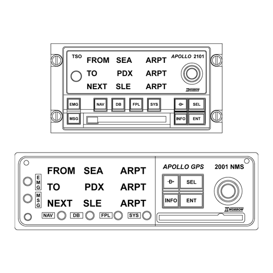
Apollo NMS Displays, Lights, and Controls Power Switch A rotary switch is located on the front panel near the left side of the 2101 NMC. A pull switch is located on the left side of the 2001 NMC. LED Display A photocell automatically adjusts the brightness of the LED (Light Emitting Diode) display. -
Page 17: Action Buttons
Apollo NMS Displays, Lights, and Controls (continued) The Small, inner knob has two functions. First, it is used to scroll through displays that pertain to the top-level displays; that is, when the diamond corner of a display. Second, when editing the display, a character (or series of characters), will flash. -
Page 18: Mode Buttons
Apollo NMS Mode Buttons Pressing a Mode button places the NMC (Nav Management Computer) into that mode. Each mode is used to perform certain types of functions. The NMC is always in one of the six modes, signified by the lighted mode annunciator. EMG (Emergency) Mode EMG mode is used to find the nearest waypoints and nearest SUAs (Special Use Airspace areas) to your present... -
Page 19: Fpl (Flight Plan) Mode
Apollo NMS Modes (continued) FPL (Flight Plan) Mode FPL mode is used to create, store, view, and edit up to 29 flight plans of up to 20 legs each and to edit the Active flight plan. It can also provide advance information about ETE, ETA, Fuel Usage, and other important flight statistics. - Page 20 Apollo NMS Features (continued) Nearest Waypoint (Emergency) Search: The NMS finds the 20 nearest waypoints of each type. The pilot can choose any of these waypoints and set a course with the Direct-To feature. The NMC (Nav Management Computer) can be set to display only those Airports and User waypoints which meet your runway length and surface requirements.
-
Page 21: Operating Logic
Apollo NMS Operating Logic Use of the Waypoint Retriever is fundamental to operating the NMS. The Waypoint Retriever is used to display specific waypoints, and is discussed in detail in Operations, Retrieving a Waypoint. The Waypoint Retriever is activated automatically when you are using a feature that requires you to display a waypoint. - Page 22 Apollo NMS Operating Logic (continued) If you wanted to fly to a different waypoint type, such as a VOR, you would begin by changing the type. Turn the Large knob until the waypoint type flashes. Select a different waypoint type by turning the Small knob. Turning the Large knob counter-clockwise causes the identifier to again flash.
-
Page 23: First Flight
Apollo NMS Before routinely using the Apollo NMS (Nav Management System) in the air, you should be quite familiar with its operation. Federal Aviation Regulations require pilots to practice SEE AND AVOID. It is therefore critical you do NOT study this manual while flying. It is recommended your first flight be made during good weather in a low traffic area. - Page 24 Apollo NMS Direct Navigation Action Underlined characters are flashing syst em (Navigation) mode Explanation The unit is in NAV mode, and the Waypoint Retriever is activated. The waypoint identifier is flashing. When an item is flashing, turning the Small knob displays other available items.
- Page 25 Apollo NMS Direct Navigation (continued) Turn the Small knob to choose the desired character. The remaining identifier characters may change as the knob is turned because the NMC (Nav Management Computer) will not display an identifier that doesn’t exist. Turn the Large and Small knobs to choose the remaining characters in the waypoint identifier.
- Page 26 [<*Heading_2] Direct Navigation (continued) Indicates additional displays (sub-pages) may be viewed by turning the Small knob. Press ENT to select the waypoint as the TO waypoint. The MNC will now provice guidance on a course from your present position to the chosen waypoint.
-
Page 27: Navigation Displays
Apollo NMS Navigation Displays The Small knob is used to scroll through the various navigation displays. The diamond ( are sub-pages which may be viewed by turning the Small knob. In this example, the sub-pages are additional navigation displays. A brief explanation of these displays appears below. For more detailed information, see the Operations section, Navigation Sub-Displays. - Page 28 [<*Heading_2] Navigation Displays (continued) If the Fuel/Air Data Sensor is installed on the NMS, three additional pages of navigation information will be available when you turn the Small knob. See Nav Mode: Navigation Sub-Displays for more information. Apollo NMS Flight time since departure is 12 minutes;...
-
Page 29: Power-Up Sequence
Operations Power-Up Sequence The power-up sequence is displayed every time the Apollo NMS is turned on. The power-up sequence begins after the NMC completes an approximately 2 second initialization of internal circuits. Following initialization, the sequence will show the owner’s name, the database version, the software version, present position, request for altimeter correction factor, and the time/date. - Page 30 Power-Up Sequence Power-Up Sequence (continued) The Self-Test introductory page is displayed for 2 seconds. The next self-test checks all of the NMC software, and takes about 4 seconds. During this time, the screen shown below is displayed. The next self-test checks the User Waypoint database. If any errors are found, the affected User Waypoints are cleared from memory, and the display shown below is displayed until the user presses ENT.
- Page 31 Operations Power-Up Sequence (continued) Remaining user-set-ups are tested next, resulting in the following message if errors are detected. Again, this message is not shown in the normal case where no errors are detected. When the test is completed successfully, the following screen is displayed for 2 seconds.
- Page 32 Power-Up Sequence Power-Up Sequence (continued) Failure to pass the datacard check causes the display to show the next page. The user must then press ENT to continue. The Owner Name page is displayed for 2 seconds. The procedure for entering owner information is described in Operations, Entering and Editing Owner Information on page 209.
- Page 33 Operations Power-Up Sequence (continued) If the Special Use Airspace (SUA) alerts have been turned off (see System Mode for more information on SUA setups), the next screen is displayed for up to 4 seconds. To turn the airspace alerts back on, press SEL when the screen shown on the previous page is displayed, then press ENT when the screen shown below appears, or press SEL to cancel.
- Page 34 Power-Up Sequence Power-Up Sequence (continued) If Emergency Search settings restricting runway lengths and/or surface types and/or lighting requirements are entered, the display below appears for up to 4 seconds. To reset the Emergency Search settings, press SEL within 4 seconds, then press ENT, as shown on the screen below, or press SEL to cancel.
- Page 35 Operations Power-Up Sequence (continued) If the total fuel entered is greater than previous Full tanks amount, the Full tanks amount is updated to the newly entered value. The total fuel entered is critical for accurate information to be displayed in the Nav items which depend on F/ADS fuel tank information.
- Page 36 Power-Up Sequence Power-Up Sequence (continued) If a valid datacard is not installed or the current position is nowhere near an airport in the database, the display below appears instead for up to 10 seconds. Again, press SEL to update the current position. The displayed position is the location of the aircraft when the power was last turned off;...
- Page 37 Operations Power-Up Sequence (continued) In most cases, updating the present position may be simplified by selecting a Reference Waypoint’s position, if the Reference Waypoint is close to the current position. To do this, press ENT when the cursor is flashing on the Reference Waypoint field, as shown below. The Waypoint Retriever will be started if ENT is pressed when the cursor is flashing on “CHG?”, the Reference Waypoint Change field.
- Page 38 Power-Up Sequence Power-Up Sequence (continued) At the end of the power up sequence, you need to decide if you want to clear the last flight plan from memory. Turn the Small, inner knob to display “YES” or “NO.” Then, press ENT. At this point, the power-up sequence is complete.
-
Page 39: Emg (Emergency) Mode
Operations Emergency Mode Displays EMG (Emergency) Mode Emergency mode helps you locate nearby waypoints quickly. In addition to being useful in an emergency, this mode provides a quick method of locating nearby waypoints in case of a diversion by ATC. The databases included in the search are Airport, VOR, NDB, INT (Intersection), and User. -
Page 40: Emg (Emergency) Mode Organization
Emergency Mode Displays EMG (Emergency) Mode Organization The figure below illustrates the organization of (EMG) Emergency mode. CHOOSE SEARCH WAYPOINT RUNWAY LIMITS NEAREST HOME PAGE NEAREST Airport NEAREST NEAREST NEAREST NEAREST USER WAYPOINT NEAREST RETRIEVER Airport NEAREST NEAREST NEAREST NEAREST Airport Airport NEAREST... -
Page 41: Emergency Mode Displays
Operations Emergency Mode Displays Emergency Mode Displays The following are examples of Emergency Mode displays. The display below shows the second nearest airport to your present position (PPOS). The waypoint identifier is shown in place of the PPos if you are searching around a waypoint other than your present position. - Page 42 Emergency Mode Displays Operations Emergency Mode Displays (continued) Turning the Small knob clockwise displays all the nearest waypoints in the database in sequence. Below is an example of the 5th closest VOR. The display below may be selected with the Large knob after entering EMG mode, and is used to display the nearest SUAs (Special Use Airspace areas).
- Page 43 Operations Emergency Mode Displays Emergency Mode Displays (continued) The display below may be selected with the Large knob after entering EMG mode, and is used to set the runway search limits. The surface limit may be set for “Hard”, “Hard/Soft”, or “Hard/Soft/Water”. Lighting requirements (“LIT:”) may be set for “YES”...
-
Page 44: Emg Mode Procedures
Emergency Mode Displays Operations EMG Mode Procedures Emergency Search/Direct-To Navigation The following procedure is used to display the nearest waypoints to your position, and navigate directly to any of them. Flow Chart PRESS TURN TO DISPLAY DESIRED DATABASE TYPE TURN TO DISPLAY THE DESIRED WAYPOINT PRESS PRESS... - Page 45 Operations Emergency Search/Direct-To Navigation (continued) Action Emergency Mode Displays Explanation The system is in EMG mode. The nearest a i r p o r t t h a t me e t s y o u r r u n w a y requirements is displayed.
- Page 46 Emergency Mode Displays Emergency Search/Direct-To Navigation (continued) Pressing the DIRECT-TO button activates the Waypoint Retriever. Pressing ENT enters a direct course to the waypoint. Operations...
-
Page 47: Searching Around A Waypoint
Operations Searching Around a Waypoint The following procedure is used to locate waypoints that are nearby a selected waypoint. You should understand use of the Waypoint Retriever before executing this procedure. The Waypoint Retriever is described in Operations, Retrieving a Waypoint. Flow Chart In this flow chart, waypoints are retrieved by identifier. - Page 48 Emergency Mode Procedures Searching Around a Waypoint (continued) Action 3. Display the desired waypoint. Explanation Press EMG and then turn the Large knob to display the “Choose Waypoint To Search Around” page. Pressing ENT activates the Waypoint Retriever, and the first character in the waypoint identifier flashes.
-
Page 49: Searching Around A Waypoint
Operations Searching Around a Waypoint (continued) Press INFO and then turn the Small knob to examine details about the displayed waypoint. Press INFO again to return to the previous screen. INFO Emergency Mode Procedures Pressing ENT enters the reference waypoint. The NMC displays the nearest airport to the reference waypoint. -
Page 50: Setting Runway Limits
Emergency Mode Procedures Setting Runway Limits The following procedure is used to choose the runway length, surface and lighting you require. When using Emergency Search or Search Around a Waypoint, the NMC will display only those waypoints that meet or exceed the runway requirements you specify. If a runway length of 0 feet is chosen, you cannot set runway surface or lighting limits. - Page 51 Operations Setting Runway Limits (continued) Action Emergency Mode Procedures Explanation In EMG mode, turn the Large knob to display the Runway Limits page. Pressing SEL activates editing. Turn the Small knob to display the desired runway length. Runway length is selected in increments of 100 feet.
- Page 52 Emergency Mode Procedures Setting Runway Limits (continued) A runway length must be selected before you can enter surface or lighting requirements. If you attempt to edit the lighting or surface type when a runway length of 0 is selected, one of the displays appears for 2 seconds.
-
Page 53: Msg (Message) Mode
Operations MSG (Message) Mode The NMC (Nav Management Computer) alerts you of conditions that may require attention. When a condition prompting a new message occurs, the MSG annunciator flashes. Once the pilot views the message(s), the MSG annunciator stops flashing, but remains lit as long as the message condition exists. -
Page 54: Message Displays
Message Displays Message Displays Messages are displayed in a prioritized order. Messages requiring immediate attention are displayed first. Below is a description of possible messages in prioritized order. Examples of typical messages are shown on the following pages. More information on Special Use Airspace messages can be viewed by pressing the INFO button. -
Page 55: Viewing Messages
Operations Viewing Messages The following procedure is used to view messages. New messages are those not yet viewed; old messages have already been viewed. Action Message Displays Explanation Pressing MSG puts the NMC in message mode, and displays the highest priority new message. - Page 56 Message Displays Operations Empty To Waypoint Message The display below shows there is no “To” waypoint in the Active flight plan. Since the Active flight plan does not contain any waypoints when the NMC is new, this message will be displayed before the first “To”...
- Page 57 Operations Message Displays In Use Position Sensor Lat/Lon Failure Message When the In Use position sensor cannot compute the Latitude and Longitude, a message is generated for either the Loran or GPS sensor. GPS RAIM Detection Not Available When RAIM detection is not available for the in-use GPS sensor, a warning is generated.
- Page 58 Message Displays Operations pressing the OBS/HOLD button and exercise the missed approach procedure. Parallel Track - Approach Conflict Before an “Enable Approach” alert can occur, parallel track must be “Off.” the following message provides the warning and a fast means to stop parallel track by pressing ENT, as indicated.
- Page 59 Operations Message Displays Set Barometer The Set Barometer alert prompts the user to change the altimeter setting after the approach has been enabled. One of three conditions may exist: altitude inputs to the NMC are not baro-corrected; altitude inputs are baro-corrected; altitude inputs are not available. Altitude Inputs without Baro-Correction If altitude inputs are not already baro-corrected, the following message prompts the user to enter the local altimeter setting.
- Page 60 Message Displays Operations altitude input is not valid or available, the following warning is given. It becomes an old message after viewing. Approach RAIM Unavailable At 2 nm to the FAF, when approach is enabled and when not holding at the FAF, the NMC checks for predicted approach mode RAIM availability at the FAF and at the MAP waypoints.
- Page 61 Operations Message Displays greater than 0.5 nm, this message is generated for 20 seconds. It becomes an old message after viewing. MCLS Non-Volatile RAM (Random Access Memory) Failure Message When the In-Use MCLS transmits a non-volatile RAM memory loss message, this message is generated. It becomes an old message after viewing.
- Page 62 Message Displays Operations Activating Oceanic Flight Phase With Primary Oceanic manually armed, the Oceanic flight phase will go active when the aircraft reaches the selected Oceanic Activation Altitude and is outside of terminal airspace.The display shown below will become a new message when the Oceanic flight phase activates and will not become an old message after being read.
- Page 63 Operations Message Displays Loss of RAIM Detection Function The following status message will be generated if the RAIM status becomes “Unavailable” (meaning there are not enough satellited to perform RAIM calculations) during Oceanic flight phase. This should be a temporary condition. The NMC will continue to provide navigation information while RAIM is unavailable.
- Page 64 Message Displays Operations Altitude Out Of Range Warning The display below shows that the current altitude is out of range for the in-use altitude sensor. Legal altitude ranges are between -1,500 and 50,000 feet. Check the pressure setting in NAV mode for a possible quick-fix.
- Page 65 Operations II Morrow has been informed by the Model 2030 manufacturer (Shadin) that Model 2030 firmware versions xx.xx.62 and earlier do not support the above message. See Page 169 for a method to view the firmware version. Many transducer failures will be indicated by dashed data fields.
- Page 66 Message Displays Operations Start Auto Descent Message The display below shows you should begin your Auto Descent. This message will be generated 20 seconds prior to auto descent. The descent rate and airspeed are set in NAV mode. In the example below, you should begin your descent to SLE at 1,500 ft/min and 250 knots.
- Page 67 Operations Message Displays Holding At The TO Waypoint This form of the Arrival Alert is provided when holding at the current TO waypoint. Next Leg Is DME Arc This form of the Arrival Alert is provided when the next TO waypoint is the end of a DME arc.
- Page 68 Message Displays Operations Auto OBS Crossing Holding Waypoint When a waypoint on hold is crossed to the FROM side the first time, the NMC will generate the following message. Note: This message is not generated when crossing the MAP. If you press ENT, the OBS Desired Track screen is displayed.
- Page 69 Operations Message Displays Data card Expired Message The display below shows the data card expiration date has passed. This message may be set any time a data card is inserted and when the NMC is powered up. The message is cleared after viewing. Data card Invalid Message The display below shows the data card is invalid, corrupted, or not properly inserted.
- Page 70 Message Displays Operations Low Battery Voltage - Keypad The low battery voltage message is generated when the NMC detects a low battery voltage in the keypad. The unit must be serviced within about a month after the first time this warning is seen. It becomes an old message after being viewed.
- Page 71 Operations Message Displays Flight Plan Transmit Failure This message is generated when an attempted serial Flight Plan transmission fails to be acknowledged affirmatively by the receiving NMC in under two seconds. It does not become an old message after being viewed.
-
Page 72: Displaying Sua (Special Use Airspace) Information
Message Displays Displaying SUA (Special Use Airspace) Information The following procedure is used to display information on a SUA after a SUA message has been generated. Action 1. Display the SUA message. INFO INFO Explanation In MSG mode, display the message alerting you to an SUA. - Page 73 Operations Message Displays SUA (Special Use Airspace) Nearest Airspace Info The values for ceiling and floor may be any number of positive feet less than 100,000. Values may also be Unlimited, Ground, Flight Level (FL) followed by a number such as 050, Unknown, or NOTAM (NOtice To Air Men).
- Page 74 Message Displays Operations Inside SUA Message The display below shows you are inside an SUA, in this example the SAN DIEGO Class B airspace.
- Page 75 Operations NAV (Navigation) Mode NAV mode displays Bearing, Track, Distance, Position, and other navigation information. Up to twelve pages (nine pages without the Fuel/Air Data Sensor) of navigation information may be displayed by turning the Large knob, or automatically in sequence (Auto Nav Scroll).
-
Page 76: Nav (Navigation) Mode
NAV (Navigation) Mode NAV Mode (continued) The figure below illustrates the organization of NAV mode. HOME PAGE PROG REQUIRED PAGE INFO RAIM PRN01 PREDICTION OCEANIC STATUS*** ALTITUDE CURRENT ASSIST: ALTITUDE BARO PR* SENSOR** PARALLEL TRACK IN-USE FIRST STANDBY POSITION SENSOR SENSOR MANUAL AIR SPEED... -
Page 77: Nav Displays
Operations NAV Displays NAV Displays Top-Level Nav Displays In NAV mode, turning the Large knob displays the pages depicted below, called “Top-Level” displays. In all modes, the Large knob is turned to scroll through Top-Level displays. The Required Navigation Information Display is depicted below. In this example, the top line shows the TO waypoint (i.e. - Page 78 NAV Displays Operations Top-Level Nav Displays (continued) Turning the Large knob one increment clockwise after entering NAV mode displays the screen depicted below. Altitude Assist is only available if the system includes a F/ADS or an altitude encoder. The Altitude Assist Altimeter Setting display is used to enter the current local altimeter setting (sea-level barometric pressure).
-
Page 79: Nav Displays
Operations NAV Displays RAIM.” Once RAIM prediction is accomplished the top line will display either “RAIM Available” or “RAIM Unavailable.” If manual RAIM prediction is temporarily locked out due to the automatic RAIM prediction required for approach operation, the top line will read “NMC RAIM Busy...”... - Page 80 NAV Displays Operations The following status is displayed when there is a RAIM alarm and a value for the Position Uncertainty is available. Fault Detection and Exclusion The NMC will automatically attempt to detect and exclude unhealthy satellite data from calulations during the Oceanic flight phase. When a sucessful exclusion occurs, the NMC will display the following message (## indicates a satellite PRN number).
- Page 81 Operations NAV Displays Top-Level Nav Displays (continued) The Parallel Course Offset display is depicted below. In this example, the offset is 1.4 nm to the right, and in Standby status. The offset is not in effect until the “In Use” status is entered. For procedural information, see Operations, Parallel Course Offset.
-
Page 82: Navigation Sub-Displays
NAV Displays Operations Arc Assist Display The Arc Assist page helps you to navigate arcs, such as DME arcs in non-precision approaches or for user-defined arcs used to conduct aerial searches via increasingly larger circles. Press ENT to get navigation information about the displayed waypoint. - Page 83 Operations NAV Displays...
-
Page 84: Eight Character Nav Items
NAV Displays Operations If the Fuel/Air Data Sensor is part of your system, the following default sub-pages are also available. Eight Character Nav Items Each navigation item explained below uses half of a display line. All of these items are available when you customize your navigation displays. The BRG (Bearing) Nav item, depicted below, shows the magnetic bearing to the To waypoint from your present location. -
Page 85: Sixteen Character Nav Items
Operations NAV Displays The TAE (Track Angle Error) Nav item, depicted below, shows the difference between DTK and TRK. In this example, TAE is 007 The Ground Speed Nav item is depicted below. In this example, the ground speed is 179 knots. The Elapsed Flight Time Nav item is depicted below. - Page 86 NAV Displays Operations The Track and Bearing Nav item is depicted below. The display indicates the current magnetic track and the magnetic bearing to the To waypoint. When the track and bearing are the same, you are flying directly toward the waypoint, and only the track is displayed.
- Page 87 Operations NAV Displays The UTC (Universal Coordinated Time) Nav item is depicted below. For GPS sensors to initialize properly, the UTC time must be correct. The Estimated Time of Arrival (ETA) Nav item is depicted below. ETA is given in UTC (Universal Time Coordinates) to the current To waypoint. In this example, ETA to Portland International is 14 hours, 23 minutes, and 3 seconds.
- Page 88 NAV Displays Operations The sixteen character Ground Speed Nav item is depicted below. In this example, the ground speed is 147 knots. The Hold Altitude Deviation Nav item is depicted below. This item shows the distance you are above or below the chosen Hold altitude. In this example, the distance above the hold altitude is 350 feet.
- Page 89 Operations NAV Displays The Fuel Remaining Nav item is depicted next. It shows the total fuel on board minus the fuel in the reserve tanks. The units of measurement may be set in System Mode: System Info. Requires F/ADS. The Fuel Range Nav item, shown below, displays the total distance which the plane can be flown given the current burn rate and the amount of remaining non-reserve fuel.
- Page 90 NAV Displays Operations The Density Altitude Nav item is shown next. Requires F/ADS or ARINC 429 Air/Data sensor and XYZ heading input. The Mach Number Nav item is depicted below. Requires F/ADS. The Turn Rate Nav item, which displays the current rate of turn of the plane, is shown next.
-
Page 91: Raim Predict Ignore List Sub-Displays
Operations RAIM Predict Ignore List Sub-Displays The RAIM Predict Ignore List (RPIL) pages allow the user to specify satellite outages as presented in NOTAMs (Notice to Airmen) or NANUs (Notice Advisory to NAVSTAR Users). This list is only used for RAIM prediction and is not used in navigation. To Access the RPIL pages in NAV mode, rotate the Large knob to the RAIM predict page, then rotate the Small knob to display the RPIL page for the satellite (listed by PRN number) that you want to exclude from the RAIM... - Page 92 NAV Displays Operations NOTES...
-
Page 93: Nav Mode Procedures
Operations NAV Mode Procedures This section details the procedures used in NAV mode. Displaying Nav Information The following procedure is used to display the various Nav pages. Action Starting/Stopping Auto Nav Scroll This feature automatically displays navigation screens sequentially for a specified amount of time, from 1 to 9 seconds per display. -
Page 94: Displaying Present Position
Nav Mode Procedures Displaying Present Position The NMC constantly updates your present position. Loran GRIs, triads, and GPS satellites are automatically chosen by the NMC. If desired, you may enter the GRI/Triad manually in SYS mode. The following procedure is used to display the position calculated by each sensor in the system. -
Page 95: Selecting A Position Sensor
Operations Selecting a Position Sensor The following procedure is used to choose the In Use position sensor. Action Nav Mode Procedures If a position sensor has not communicated with the NMC since power-up, the Not Communicating display, depicted below, appears. Explanation In NAV mode, turn the Large knob to display the Position Summary page. -
Page 96: Automatic And Manual Position Sensor Selection
Nav Mode Procedures Automatic and Manual Position Sensor Selection Position Sensor Selection allows you to choose which of the position sensors installed on the Navnet network to use for navigation. Automatic Position Sensor Selection allows the NMC to automatically choose which position sensor is being used for navigation. Manual Position Sensor Selection disables the automatic option and allows you to choose your position sensor. - Page 97 Operations While Automatic Position Sensor Selection can be started or canceled using the method described above, it can also be canceled by manually selecting a different position sensor, as follows: Action Nav Mode Procedures Turn the Small knob to display the Automatic/Manual page, and press SEL to activate editing.
- Page 98 Nav Mode Procedures Editing Manual RAIM Prediction Fields The Apollo NMC allows the user to manually check predicted RAIM availability for any waypoint, date, and time contained by the data base. Pressing ENT activates the position sensor and cancels Automatic Position Sensor Selection.
- Page 99 Operations Editing RAIM Predict Ignore List The Apollo NMC allows the user to specify satellite outages for RAIM predictions using information presented in NOTAMs or NANUs. Nav Mode Procedures Press ENT to access the database and use the Large and Small knobs to select a waypoint.
-
Page 100: Clear Raim Predict Ignore List
Nav Mode Procedures Clear RAIM Predict Ignore List The user has the option to clear the RPIL available from the main RAIM prediction page. To indefinitely remove a satellite from service, including over power ups, rotate the Small knob until REMOVE is displayed in the hours location and press ENT. -
Page 101: Altitude Sensor Selection
Operations Altitude Sensor Selection Altitude Assist requires the system include an altitude encoder or Fuel/Air Data Sensor (F/ADS). This procedure is used to select which of these sensors is used for altitude data. In this example, the current sensor is an altitude encoder, and is changed to an F/ADS. The same procedure is used to change back. - Page 102 Nav Mode Procedures Turn the Large knob to choose the desired sensor. Press ENT to enter the sensor choice. Operations...
-
Page 103: Setting The Altimeter (Barometric Pressure)
Operations Setting the Altimeter (Barometric Pressure) Each time the system is powered up, the barometric pressure is automatically set to standard pressure, 29.92” (or 1013 mb). This procedure is used to enter the current altimeter setting (barometric pressure). These pages are not available if an ARINC 429 Air/Data sensor is installed in the system. -
Page 104: Setting/Editing Hold And Buffer Altitudes
Nav Mode Procedures Setting/Editing Hold and Buffer Altitudes Altitude Assist features require that the system include an altitude input device. The NMC alerts you when you’ve ascended/descended into the Hold Buffer, or have strayed outside of the buffer. The Buffer Altitude is the altitude above and below your Hold altitude at which you want to be alerted with a message. -
Page 105: Starting/Stopping Altitude Hold
Operations Starting/Stopping Altitude Hold Altitude Assist features require the system include a F/ADS or an altitude encoder sensor. The following procedure is used to start or stop the Altitude Hold feature. When active, Altitude Hold alerts you with a message when you have ascended/descended into the buffer, or when you stray outside the buffer. - Page 106 Nav Mode Procedures Action Explanation In NAV mode, turn the Large knob to display the Altitude Assist page. Turn the Small knob to display the Hold Altitude page. Pressing ENT activates Altitude Hold. Pressing ENT again deactivates the feature. Operations...
-
Page 107: Setting/Editing Auto Descent Values
Operations Nav Mode Procedures Setting/Editing Auto Descent Values Altitude Assist features requires the system to include either a F/ADS or an altitude encoder sensor. The Auto Descent feature allows you to input a desired End Altitude, an Offset Distance from a desired Auto Descent Waypoint from the Active flight plan, a desired Feet per Minute Descent rate, and an expected Ground speed. - Page 108 Nav Mode Procedures Operations Setting/Editing Auto Descent Values (continued) Flow Chart...
- Page 109 Operations Set up your Auto-Descent by selecting: Distance from destination waypoint (0 - 99 nm) or Offset Distance Ending altitude (-1,500 - 50,000’ in 50’ steps) Descent rate (100 - 5,000’/min in 10’/min steps) Estimated ground speed (50 - 600 kts) Action Nav Mode Procedures Explanation...
- Page 110 Nav Mode Procedures Turn the knob to the Ending LARGE Altitude value. Turn the to change the value. The default value is 1000 ft above the airport elevation. Turn the knob to the Auto SMALL Descent page, if necessary. Your recommended glide slope and ending altitude are shown.
- Page 111 Operations Nav Mode Procedures Notes...
-
Page 112: Starting/Stopping Auto Descent
Nav Mode Procedures Starting/Stopping Auto Descent Altitude Assist features require the system to include an altitude input device. The following procedure is used to start or stop Auto Descent. Auto Descent calculates the distance remaining in your Active flight plan, and based on the glide path angle, the altitude you are descending to, and your present altitude, alerts you with a message when you should begin and end your descent. -
Page 113: Parallel Course Offset
Operations Parallel Course Offset The NMC allows you to fly a course parallel to the course you’ve defined by entering a parallel course offset. This may be useful in avoiding weather or other obstacles. Activating/Deactivating/Editing Parallel Course Offset The following procedure is used to activate, deactivate, or edit a parallel course. - Page 114 NAV Mode Procedures Activating/Deactivating/Editing Parallel Course Offset (continued) If necessary, turn the Large knob to make the direction setting flash, and turn the Small knob to change the direction. Turn the Large knob to make the offset value flash. Turn the Small knob to choose the amount of the offset.
-
Page 115: Manual Air Speed
Operations Manual Air Speed The 2101 can be setup to allow you to manually enter an air speed. The Manual Airspeed selected will be used as the True Air Speed. By entering an air speed, may then view Wind Speed, Magnetic Wind Direction, and True Wind Direction when these Nav items are selected. -
Page 116: Countdown Timer
NAV Mode Procedures Countdown Timer The countdown timer is set in hours, minutes, and seconds. When the timer reaches 00:00:00 a message is generated, and the MSG light flashes. After viewing the message, the message clears. A maximum time of 99:59:59 may be entered. Once the timer is started, you may change modes or displays without disturbing the Countdown Timer. -
Page 117: Dme Arc Assist
Operations DME Arc Assist See the DME-ARCs (Arc Assist) section in the Approach portion of this manual. See page 249. Waypoint Distance Page This page shows the cumulative distance from your current position to each waypoint in the active flight plan starting with the active leg. Turn the Small knob to view the next set of waypoints in your active flight plan. -
Page 118: From-To-Next Waypoint Eta Page
NAV Mode Procedures From-To-Next Waypoint ETA Page This page displays the ETA for each waypoint in your active flight plan from your current position, starting with the active leg. Turn the Small knob to view the next page of waypoints. The time will not be shown for the same reasons as in the Waypoint Distance page, if the ground speed is zero, or if 3-D positioning is lost. - Page 119 Operations Flow Chart PRESS TURN TO DISPLAY THE FROM /TO/NEXT PAGE PRESS TO ACTIVATE EDITING TURN TO POSITION THE FLASHING "CHG?" IN PLACE OF THE IDENTIFIER YOU WANT TO CHANGE PRESS TO ACTIVATE THE WAYPOINT RETRIEVER IS THE DESIRED WAYPOINT IDENTIFIER DISPLAYED PRESS NAV Mode Procedures...
- Page 120 NAV Mode Procedures Inserting and Editing a From/To/Next Waypoint (cont’d) Action Explanation In NAV mode, turn the Large knob to display the From/To/Next page. The current From, To, and Next identifiers are displayed. Blank lines appear in spaces where there are no waypoints. Press SEL to activate editing.
- Page 121 Operations Inserting and Editing a From/To/Next Waypoint (cont’d) 5. Display the desired waypoint. NAV Mode Procedures Pressing ENT activates the Waypoint Retriever. Use the Waypoint Retriever to display the desired waypoint. The Waypoint Retriever is described in Operations, Retrieving a Waypoint. Press ENT to enter the displayed waypoint into the Active flight plan.
-
Page 122: Hold/Continue The From/To/Next Sequencing
NAV Mode Procedures Hold/Continue the From/To/Next Sequencing The following procedure is used to change the flight plan status to HOLD, or to resume flight plan sequencing after holding. HOLD prevents the Active flight plan waypoints from sequencing. While the flight plan status is HOLD, the NMC continues to show the bearing to the TO waypoint even after you have passed the waypoint. -
Page 123: Db (Database) Mode
Operations DB (Database) Mode Database mode is used to access, modify, create, and delete waypoints and waypoint information. Airport, VOR, NDB, and Intersection waypoints are stored on the data card, and accessed in DB mode. These waypoints, and information on these waypoints, may not be changed or deleted. - Page 124 DB (Database) Mode Database Mode (continued) The figure below illustrates the organization of Database mode. MODIFY USER WAYPOINT DELETE WAYPOINT COMMENT ACCESS DATABASE HOME PAGE CREATE LAT/LON USER WPT CREATE RAD/DIST USER WPT DELETE USER WAYPOINT MODIFY WAYPOINT RETRIEVER WAYPOINT COMMENT DELETION WAYPOINT...
-
Page 125: Databases
Operations Database mode (DB mode) is used to access and display waypoints stored in databases. The datacard stores four databases—Airports, VORs, NDB’s, and Intersections (INT). The NMC (Nav Management Computer) stores User waypoints. It is useful to think of these databases as “drawers”... -
Page 126: Database Information
Databases Database Information Datacards are inserted in the slot below the knobs and buttons. A datacard may be inserted while the unit is off, or when powered-up. When a datacard is removed and stored, be sure to keep it free from moisture and dust. -
Page 127: Vor/Ndb/Int (Intersection) Databases
Operations VOR/NDB/INT (Intersection) Databases Identifier City, State, Country Bearing from your from your present position Latitude/Longitude User Database Identifier Distance from your present position Waypoint Latitude/Longitude Databases Name Frequency of VOR or NDB Distance from your present position Bearing from your your present position User defined runway length... -
Page 128: Database Displays
Databases Database Displays In any mode, information about a displayed waypoint may be shown by pressing the INFO button, and turning the Small knob. Below are examples of the information pages for the waypoint PDX (Portland International airport). Operations PDX airport facility name is Portland International, located in Oregon, USA. - Page 129 Operations Database Displays (continued) Databases CTAF frequency is 118.70. Ground control frequency is 121.90. Clearance delivery frequency is 119.10. Approach frequency is 118.10. Approach frequency is 126.90. Approach frequency is 133.00. Departure frequency is 118.10. Departure frequency is 133.00. ILS frequency is 109.90. Runway 10R ILS frequency is 111.30.
- Page 130 Databases Database Displays (continued) Operations PDX runway 10R/28L. 11,000 feet long with a hard surface and ILS. The runway is lighted. PDX runway 10L/28R 8,000 ft long with a hard surface and ILS. The runway is lighted. PDX runway 02/20 7000 feet long with a hard surface and LOC.
-
Page 131: Db Mode Procedures
Operations DB Mode Procedures Retrieving a Waypoint These procedures are used to display a waypoint using the Waypoint Retriever. Waypoints may be retrieved (displayed) by searching according to identifier, city name, or facility name. Before retrieving a waypoint, be sure the data card is inserted in the data card slot. Once the waypoint is displayed—... - Page 132 DB Mode Procedures Waypoint Retrieval by Identifier (continued) Action Explanation In DB mode, turn the Large knob to display the Access Database page. Pressing ENT activates the Waypoint Retriever. Turn the Large knob to make the database type flash. Turn the Small knob to display the desired database.
- Page 133 Operations Waypoint Retrieval by Identifier (continued) If you see “DUP”on the 3rd line, there are duplicate facilities with the same identifier. Press SEL and use the Small knob to view duplicates. DB Mode Procedures Turn the Large knob to make the identifier flash.
-
Page 134: Retrieving A Waypoint By City/Facility Name
DB Mode Procedures Retrieving a Waypoint by City/Facility Name The following procedure is used to retrieve a waypoint by the name of the city in which it is located, or by the name of the waypoint facility. For example, if you did not know the identifier for McNary Field in Salem, Oregon is SLE, you could display the waypoint by searching for the city name, Salem, or by searching for the facility name, McNary Fld. - Page 135 Operations Retrieving A Waypoint By City\Facility Name (continued) Action DB Mode Procedures Explanation In DB mode, turn the Large knob to display the Access Database Page. Pressing ENT activates the Waypoint Retriever. Turn the Large knob to make the database type flash. Turn the Small knob to display the desired database.
- Page 136 DB Mode Procedures When you press SEL a second time, the selected field will flash. Turn the Small knob to scroll through all items similar to the selected characters. For instance, if you had selected “M” for the first character and “E”...
-
Page 137: Waypoint Information And Comments
Operations Waypoint Information and Comments These procedures are used to display information and personal comments on waypoints. Waypoint information is stored on the data card, and can not be changed. Comments you create are stored in the NMC, and may be edited and deleted. -
Page 138: Entering/Editing Waypoint Comments
DB Mode Procedures Entering/Editing Waypoint Comments The following procedure is used to enter or edit a waypoint comment. A waypoint comment is a message you compose. A comment may be entered on any waypoint in any database; however, the NMC stores a maximum of 200 comments. - Page 139 Operations Entering/Editing Waypoint Comments (continued) Action 1. Display the desired waypoint. INFO DB Mode Procedures Explanation In any mode, display the desired waypoint. In this example, PDX (Portland International) is displayed in DB mode. Pressing INFO activates the information function. Turn the Small knob to display the waypoint comment page.
- Page 140 DB Mode Procedures Entering/Editing Waypoint Comments (continued) INFO Pressing SEL activates comment editing. If a comment on the waypoint has already been entered, the comment appears, and the first character is flashing. If you create a new comment, a flashing cursor appears on an otherwise blank display.
-
Page 141: Deleting A Waypoint Comment
Operations Deleting a Waypoint Comment The following procedure is used to delete a waypoint comment. The NMC will store a maximum of 200 comments. Once 200 comments have been entered, you must delete an existing comment to make room for a new comment. Action DB Mode Procedures Explanation... - Page 142 DB Mode Procedures Deleting a Waypoint Comment (continued) Pressing ENT deletes the displayed waypoint comment. Pressing any mode button instead of ENT exits the Delete Waypoint Comment function without deleting a comment. Operations...
-
Page 143: User Waypoints
Operations DB Mode Procedures User Waypoints User waypoints are waypoints entered and named by you. You may create a User waypoint at any location by entering Latitude/Longitude coordinates, or by entering the radial/distance from another waypoint. If you create a User waypoint by entering a radial/distance, the NMC will calculate the Latitude/Longitude of the waypoint. - Page 144 DB Mode Procedures Creating a User Waypoint by Latitude/Longitude (continued) Action Explanation In DB mode, turn the Large knob to display the Create User Waypoint by Lat/Lon page. If the maximum of 500 User waypoints already exist, the display below appears, and you must delete a User waypoint before you may create a new waypoint.
- Page 145 Operations Creating a User Waypoint by Latitude/Longitude (cont’d) If you want to quickly establish a waypoint as you fly over a position, you may choose to accept the automatically assigned numerical identifier instead of naming the waypoint. Pressing ENT at this point in the procedure eliminates the need to execute steps 3 and 4.
-
Page 146: Creating A User Waypoint By Radial/Distance
DB Mode Procedures Operations Creating a User Waypoint by Radial/Distance The NMC allows you to create User waypoints by specifying the radial and distance from an existing waypoint. This reference waypoint may be in any database, including the User database. Do not “chain” radial/distance waypoints. - Page 147 Operations Creating a User Waypoint by Radial/Distance (continued) Action DB Mode Procedures Explanation In DB mode, turn the Large knob to display the Create User Waypoint By Radial/Dist page. If the maximum of 500 User waypoints already exist, the display below appears, and you must delete a User waypoint before you may create a new waypoint.
- Page 148 DB Mode Procedures Creating a User Waypoint by Radial/Distance (continued) 5. Display the desired waypoint. Turn the Large knob so that “CHG?” flashes in place of the reference waypoint identifier. Pressing ENT activates the Waypoint Retriever. Use the Waypoint Retriever to display the desired waypoint.
- Page 149 Operations Creating a User Waypoint by Radial/Distance (continued) DB Mode Procedures Pressing ENT enters the displayed waypoint as the reference waypoint, and displays the Reference Waypoint page. Turn the Small knob to choose the first radial value number. Use the Large and Small knobs to choose the remaining numbers in the radial and distance values.
- Page 150 DB Mode Procedures Creating a User Waypoint by Radial/Distance (continued) Turn the Small knob to display the desired character. Turn the Large knob to make the next character you want to change flash. Repeat as necessary to edit the identifier, latitude, longitude, and the runway length.
-
Page 151: Editing A User Waypoint
Operations Editing a User Waypoint The following procedure is used to change the identifier, latitude/longitude coordinates, or runway length of an existing User waypoint. Flow Chart PRESS TURN TO DISPLAY THE MODIFY USER WPT PAGE PRESS TURN TO DISPLAY THE DESIRED USER WAYPOINT PRESS DB Mode Procedures... - Page 152 DB Mode Procedures Editing a User Waypoint (continued) Action Explanation In DB mode, turn the Large knob to display the Modify User Waypoint page. If there are no User waypoints stored, the display below appears. The NMC displays the Find Waypoint to Modify page.
- Page 153 Operations Editing a User Waypoint (continued) DB Mode Procedures Pressing ENT retrieves the waypoint, and activates editing. If the waypoint is in the Active flight plan, it cannot be modified, and the display below appears for approximately 3 seconds. The Find Waypoint to Modify page is then displayed.
- Page 154 DB Mode Procedures Editing a User Waypoint (continued) Press ENT to save the changes. If the waypoint is in an inactive flight plan, the display below appears for approximately 3 seconds. After 3 seconds, or if the waypoint is not in a flight plan, the display below appears.
-
Page 155: Deleting A User Waypoint
Operations Deleting a User Waypoint The following procedure is used to delete a User waypoint. This may be necessary to make room for a new User waypoint. Action DB Mode Procedures Explanation In DB mode, turn the Large knob to display the Delete User Waypoint page. - Page 156 DB Mode Procedures Deleting a User Waypoint (continued) Pressing ENT deletes the waypoint. Pressing any mode button instead of ENT exits this function without deleting a waypoint. The NMC will not delete any User waypoint included in a flight plan. If this is attempted, the following display appears for approximately 3 seconds.
-
Page 157: Fpl (Flight Plan) Mode
Operations FPL (Flight Plan) Mode Flight plans are specific routes between waypoints you may store in the NMC’s memory. The NMC uses this information to calculate useful flight statistics. Flight Plan mode allows you to have up to 30 stored flight plans. Twentynine of these flight plans are Inactive, waiting to be used at any time for navigation. - Page 158 Flight Plan (FPL) Mode The figure below illustrates the organization of Flight Plan mode. HOME PAGE ACTIVE PLAN INFO FLIGHT COMMENT PLAN INACTIVE INFO PLAN FLIGHT COMMENT PLAN UP TO 29 INFO PLAN INACTIVE COMMENT FLIGHT PLANS CREATE FLIGHT PLAN LEG 2 LEG 1 LEG 2...
-
Page 159: Flight Plan Summary Pages
Operations Flight Plan Summary Pages The Flight Plan Summary page displays the flight plan’s name, total distance, destination waypoint, and its status (Inactive, Active, or Hold). One of the Flight Plan Summary pages is used only to create a new Inactive flight plan. An example of a Flight Plan Summary page is shown below. -
Page 160: Creating A Flight Plan
Flight Plan (FPL) Mode Creating a Flight Plan Action Explanation Press FPL to enter FLIGHT PLAN mode, then rotate the Large knob to display the flight plan creation page, shown below. Press SEL to start flight plan creation. The first character position will flash. Tu r n t he S m a l l k no b t o c h oo se characters. -
Page 161: Inserting And Editing Flight Plan Legs
Operations Inserting and Editing Flight Plan Legs Waypoints in a flight plan may be inserted, deleted, or changed to another waypoint at any time in Flight Plan mode. In addition, the third line of the Flight Plan Leg pages may be customized to display one of several types of information. - Page 162 Flight Plan (FPL) Mode If waypoints have already been entered, the Flight Plan Leg page may be similar to this. Pressing SEL will start the cursor flashing, indicating that Flight Plan Leg page editing has begun. Rotate the Large knob to move the cursor Turn the Small knob to view available fields.
-
Page 163: Manually Selecting A Flight Plan Leg
Operations Pressing ENT when the correct option is flashing enters the flashing option. The meaning and handling of the flashing options are described next. Press SEL to stop editing. Manually Selecting a Flight plan Leg Approach operations often result in the need to manually select a leg of the active flight plan. -
Page 164: Updating Leg Information
Flight Plan (FPL) Mode Updating Leg Information The bottom line of Flight Plan Leg pages is used to display the customizable Leg Information. Several types of Leg Information may be selected for viewing, and are described next in Leg Information Options. - Page 165 Operations ETA? The ETA? field shows the Estimated Time of Arrival at the To waypoint of the currently displayed leg of the flight plan. ETA? uses the Estimated Ground Speed value (described in Using Flight Plan Summary Options) to figure the ETA. In the Active flight plan, ETA? uses the latest available position as the starting reference point.
- Page 166 Flight Plan (FPL) Mode ETE? The ETE? field shows the Estimated Time En route to the To waypoint of the currently displayed leg of the flight plan, using the Estimated Ground Speed value (described previously in Using the Flight Plan Summary Options) to figure the ETE.
-
Page 167: Fuel At
Operations FUEL AT Fuel At is the fuel remaining at the displayed leg’s To waypoint. Fuel At information is only available for the Active flight plan with a Fuel/Air Data Sensor installed on NAVNET, and a ground speed of greater than 20 knots. If these inputs are not available, the number is dashed. - Page 168 Flight Plan (FPL) Mode If the Flight Plan Comment has not been entered for the flight plan, the following page is displayed to prompt you to press SEL to begin entering a Flight Plan comment. Press SEL to edit the Flight Plan Comment.
-
Page 169: Accessing Flight Plan Summary Options
Operations INFO Accessing Flight Plan Summary Options Several Flight Plan Summary Options are available to assist you in maintaining your flight plans when the Flight Plan Summary page is displayed. Shown below is a simple explanation for accessing these Flight Plan Summary Options. A more detailed explanation of the purpose of each of these options is given later. -
Page 170: Using Flight Plan Summary Options
Flight Plan (FPL) Mode Using Flight Plan Summary Options A list of each Flight Plan Summary Option, along with explanations of their meanings, is given below. Activate? Pressing ENT when “Activate?” is displayed copies the Inactive flight plan into the Active plan. The new Active flight plan is activated with the new waypoint information. - Page 171 Operations Hold? Pressing ENT when “Hold?” is displayed prevents the sequencing of legs in the Active flight plan, effectively putting the Active flight plan on Hold at the current To waypoint. “HOLD” may also be activated in the FROM/TO/NEXT page in NAV mode or by pressing the external OBS/HLD button when installed.
- Page 172 Flight Plan (FPL) Mode Reactivate? Pressing ENT when “Reactivate?” is displayed restarts the Active flight plan, starting sequencing from leg #1. Rename Plan? Pressing ENT when “Rename Plan?” is displayed allows you to rename an Inactive flight plan. After pressing ENT, rotate the Large and Small knobs to rename the flight plan, then press ENT to save the new flight plan name.
- Page 173 Operations Clear Waypoints? Pressing ENT when “Clear Waypoints?” is displayed removes all of the leg waypoints from the flight plan, active or inactive. If this option is used on the Active flight plan, all of the leg waypoints are removed. This will remove the destination waypoint and all Nav data will be flagged as invalid until a new destination is selected.
-
Page 174: Cancel Oceanic
Flight Plan (FPL) Mode Arm Oceanic Pressing ENT when the “Arm Oceanic” option is flashing, arms the Oceanic flight phase when the phase is inactive and the Oceanic function is enabled. Activation Altitude After pressing the ENT button, the second line of the display changes to show the Oceanic Activation Altitude flashing. -
Page 175: Direct-To And The Active Flight Plan
Operations Flight Plan (FPL) Mode Direct-To and the Active Flight Plan When a Direct-To waypoint is entered following the use of the DIRECT-TO button, the Active flight plan is updated to reflect the change. The currently active From waypoint of the Active flight plan is changed to DIRECT, to reflect that you are now flying directly to the To waypoint. - Page 176 Flight Plan (FPL) Mode Operations NOTES...
-
Page 177: System (Sys) Mode
Operations System (SYS) Mode SYS (System) mode is used to display information and enter settings and adjustments into the Apollo NMS (Navigation Management System). SYS mode is divided into four “sub-states.” After entering SYS mode, turning the Large knob scrolls through the sub-states. The four sub-states are: Navigation Info - Functions pertaining to navigation information, such as Airspace Setup, NAV Mode Display... -
Page 178: System Mode
System (SYS) Mode System Mode The figure below illustrates the organization of SYS Mode. POSITION SENSORS MISCELLANEOUS SENSORS HOME PAGE NAVIGATION INFORMATION SYSTEM INFORMATION POSITION SENSORS SUB-STATE MISCELLANEOUS SENSORS SUB-STATE NAV INFO SUB-STATE SYS INFO SUB-STATE Operations... -
Page 179: Sys Mode Displays
Operations SYS Mode Displays Top-Level Displays Top-Level functions are accessed by entering SYS Mode and turning the Large knob. These functions are: Navigation Info, System Info, Position Sensors, and Miscellaneous Sensors. Pressing ENT places the system in the sub-state described on the top line. For example, pressing ENT when the top-level page reading “NAVIGATION INFO”... -
Page 180: Navigation Info Sub-State Displays
SYS Mode Displays Position Sensors Pressing ENT when the screen below is displayed provides access to Loran/GPS sensor settings and data. Miscellaneous Sensors Pressing ENT when the screen below is displayed provides access to Air Data Info, Fuel Info data, and pressure altitude. Navigation Info Sub-State Displays Airspace Setup The navigation information sub-state screens are used to display and... - Page 181 Operations Airspace Select The display below is used to select the type of SUAs that will generate alert messages. A similar page is displayed for each type of SUA. SUA alert options include: Class B and C airspaces, MOAs, Training Areas, Unknown SUAs, Alert Areas, Caution Areas, Danger Areas, Restricted Areas, Prohibited Areas, and Warning Areas.
- Page 182 SYS Mode Displays Navigation Info Sub-State Displays (continued) Nav Mode Display Programming The display below is used to customize Nav pages. This feature allows you to choose the specific navigation items displayed in NAV mode. Magnetic Variation The display below shows the magnetic variation is set on automatic, and is currently 09 W (West).
-
Page 183: System Info Sub-State Displays
Operations Direct-To Entry The display below is used to choose the Direct-To Entry Option, which affects how entering a Direct-To waypoint is handled by the Active flight plan. System Info Sub-State Displays The system information Sub-State displays show information and settings pertaining to the NMS (Navigation Management System). - Page 184 SYS Mode Displays System Info Sub-State Displays (continued) Baro Measure Units The screen below is used to choose the measurement units used in barometric pressure adjustment displays in inches or millibars. NMC Software Version The display below shows the NMC software version and part number. The software version information may be important when servicing/troubleshooting the NMC.
-
Page 185: Display Test
Operations System Info Sub-State Displays (continued) GPS Firmware Version The display below shows the internal GPS Firmware (FW). The version shown is 016. Loran Software Version The display below shows the Loran 1 software version is 1.00, and the antenna is top mounted. AirData Computer Version This display shows the version of the AirData Computer. - Page 186 SYS Mode Displays Position Sensors Sub-State Displays The position sensor screens display information about each Loran and GPS sensor included in the system. Loran Information The display below shows data for Loran 1, and a similar screen is displayed for each Loran sensor. Also, each Loran sensor tracks two GRIs, and turning the Large knob displays data for the other GRI.
- Page 187 Operations “cycle” - the station is in cycle selection, or has a cycle error. “track” - the station has acquired the signal, has successfully cycle selected, and is tracking the signal. The bottom line shows the SNR (Signal to Noise Ratio, from 0 to 99), the cycle data 1 (0 to 99), and the cycle data 2 (0 to 99).
- Page 188 SYS Mode Displays Oscillator Information The display below shows the OSC (Reference Oscillator) frequency and temperature. The OSC is used in timing the station TDs. In this example, the OSC frequency is 8.000101 MHz and is at 24 Each Loran sensor tracks two GRI’s simultaneously, and can use stations from both GRIs to calculate a Latitude/Longitude position.
- Page 189 Operations Satellites In Use The next sub-page indicates the satellites that are presently being used to calculate your position. The selection of these satellites is a complex process that minimizes the error in calculating your position. The GPS satellites are always moving across the sky, so the ideal selection of satellites is constantly changing.
-
Page 190: Miscellaneous Sensors Sub-State Displays
SYS Mode Displays GPS time can also be obtained in UTC hours along with the date. Finally, the user can perform a normal reset. A normal reset sends the time, date and position to the GPS receiver. This will interrupt present navigation and restart satellite acquisition. - Page 191 Operations The first Air Data Sensor display shows: True Air Speed, which is the speed the plane is traveling relative to the surrounding air speed Indicated Air Speed, which is the speed of the plane as shown on the airspeed indicator The next display page shows: True Air Temperature, which compensates for wind chill factors...
- Page 192 SYS Mode Displays The last Air Data Sensor display shows: True Wind Direction Magnetic Wind Direction Wind Speed Fuel Data Sensor Information If the system does not include an F/ADS, the next display is the only page shown for the Fuel Data Sensor Information. If the Fuel Data Sensor information is available, the next screens are available for information on the Fuel Data Sensor.
- Page 193 Operations The next display shows: estimated Fuel Range, based on the current amount of fuel in the regular (non-reserve) tanks, current Burn Rate per hour total Fuel Used since power-up The next Fuel Data Sensor display shows: Burn Rate for the right engine Amount of Fuel Used by the right engine The next Fuel Data Sensor display shows: Burn Rate for the left engine...
- Page 194 SYS Mode Displays Each of these values may be edited by pressing SEL, rotating the Large and Small knobs, and pressing ENT to save any changes. The last Fuel Data Sensor display shows the current Fuel Measure Units which are displayed for fuel information. This information may be edited by pressing SEL, rotating the Large and Small knobs, and pressing ENT to save the changed value.
-
Page 195: Navigation Information Sub-State
Operations Navigation Information Sub-State The Navigation Information sub-state is used to modify the navigation information displays and settings. These settings include: Airspace Alert Used to adjust the Altitude Buffers, the types of SUA (Special Use Airspace) areas you want to be alerted to, and the time/distance from SUAs at which you want alerts generated. - Page 196 Navigation Information Sub-State Navigation Information Sub-State (continued) The figure below illustrates the organization of the Navigation Information sub-state. HOMEPAGE NAVIGATION INFORMATION INFORMATION AIRSPACE ALERT SETUP AUTONAV TIME NAVIGATION PROGRAMMING PAGES MAGNETIC VARIATION SETTING OCEANIC ALTITUDE FLIGHT TIMER TRIGGER SPEED DIRECT TO ENTRY CDI SCALING POSITION...
-
Page 197: Airspace Alert Settings
Operations Airspace Alert Settings The following procedure is used to edit Airspace Alert settings. Flow Chart PRESS TURN TO DISPLAY THE NAVIGATION INFO PAGE PRESS TURN TO DISPLAY THE AIRSPACE SETUP PAGE PRESS TO ACTIVATE EDITING TURN TO TURN ALERTS ON OR OFF PRESS TURN TO DISPLAY THE... - Page 198 Navigation Information Sub-State Airspace Alert Settings (continued) Action Explanation In SYS mode, turn the Large knob to display the Navigation Info page. Pressing ENT activates the Navigation Info Sub-State functions. Turn the Large knob to display the Airspace Setup page. Pressing SEL activates editing.
- Page 199 Operations Airspace Alert Settings (continued) Navigation Information Sub-State Turn the Small knob to display the Airspace Buffer page. DIST refers to the distance from SUAs. ALT refers to the Altitude Buffer. TIME refers to the time before penetrating SUAs. Pressing SEL activates editing. Turn the Small knob to display the desired distance setting.
- Page 200 Navigation Information Sub-State Airspace Alert Settings (continued) Repeat step 6. 10. Repeat steps 8 and 9 as required. Use the Large and Small knobs to edit the time setting. Pressing ENT save the changes. Turn the Small knob to display the desired Airspace Select page.
-
Page 201: Setting The Auto Nav Scroll Time
Operations Setting the Auto Nav Scroll Time The following procedure is used to set the amount of time each NAV information page is displayed during Auto Nav Scroll. Each NAV information page may be displayed for up to 9 seconds. Action Navigation Information Sub-State Explanation... -
Page 202: Programmable And Autonav Nav Pages
Navigation Information Sub-State Programmable and Autonav Nav Pages The NMC allows you to customize the Nav Information pages to display your personal choice of Nav Items on each of the programmable pages (see Eight Character Nav Items and Sixteen Character Nav Items in the Nav section starting on page 70). - Page 203 Operations Programmable and Autonav Nav Pages (continued) Navigation Information Sub-State Pressing ENT activates the Navigation Info sub-state functions. Turn the Large knob to display the Nav Mode Display Programming page. Turning the Small knob displays the Navigation Info pages, and pressing SEL activates editing.
- Page 204 Navigation Information Sub-State Programmable and Autonav Nav Pages (continued) Rotating the Large and Small knobs moves the cursor and updates the displayed fields. Pressing ENT saves any updates, and displays the Autonav Pages prompt. Turning the Small knob displays the available choices you have for keeping this page in the Autonav sequence.
- Page 205 Operations Programmable and Autonav Nav Pages (continued) One of the optional fields which may be programmed into the customizable Navigation Info pages is the Empty field. This is an eight character field, and is denoted by six flashing underscore characters (“______”) when the cursor is on the field.
-
Page 206: Restoring Default Nav Displays
Navigation Information Sub-State Restoring Default Nav Displays The following procedure is used to restore the default (factory) Nav displays. Action Explanation In SYS mode, turn the Large knob to display the Navigation Info page. Pressing ENT activates the Navigation Info Sub-state functions. Turn the Large knob to display the NAV Mode Display Programmable and Autonav page. -
Page 207: Manually Entering Magnetic Variation
Operations Manually Entering Magnetic Variation The following procedure is used to edit the magnetic variation anytime after the power-up sequence is complete. With a datacard installed, and magnetic variation set to AUTO, the NMC automatically accounts for magnetic variation. If the datacard is not inserted, you must enter the magnetic variation during power-up. - Page 208 Navigation Information Sub-State Manually Entering Magnetic Variation (continued) Action Explanation In SYS mode, turn the Large knob to display the Navigation Info page. Pressing ENT activates the Navigation Info sub-state functions. Turn the Large knob to display the Mag Variation page. Pressing SEL activates editing.
- Page 209 Operations Manually Entering Magnetic Variation (continued) Navigation Information Sub-State Turn the Large knob to make the Mag Variation value flash. Turn the Small knob to display the desired Mag Variation. Turn the Large knob to make the direction character flash. Turn the Small knob to display “E”...
-
Page 210: Changing The Oceanic Activation Altitude
Navigation Information Sub-State Changing the Oceanic Activation Altitude The following procedure is used to set the altitude at which the NMC will start and stop the Oceanic/Remote Flight Phase. The default (factory) setting is 18000 feet. Acceptable settings are from 0 to 18000 feet in 100 foot increments. -
Page 211: Editing The Flight Timer Trigger Speed
Operations Editing the Flight Timer Trigger Speed The following procedure is used to edit the flight timer trigger speed. The flight timer may be set to start at power-up, or when the ground speed exceeds from 10 to 500 knots. The default (factory) setting is 60 knots. -
Page 212: Display Units
Navigation Information Sub-State Display Units Nav displays that show distance may be selected to show either nautical miles, statute miles, or kilometers. Altitude displays may show either meters (m) or feet (ft). These selections are made in the Nav Info section of the System mode. In the Navigation Info section of the System function, turn the Large knob to the Display Units Page. -
Page 213: Description Of The Direct-To Entry Option
Operations Navigation Information Sub-State Description of the Direct-To Entry Option When you use Direct-To, the Active flight plan (and the From, To, Next information) is automatically updated. If you use Direct-To to center the CDI needle for the current “To” waypoint, or skip past the To waypoint to another waypoint already in the Active flight plan, the current leg number of the Active flight plan will be updated, if needed, so that the Direct-To waypoint matches the... -
Page 214: Editing The Direct-To Entry Option
Navigation Information Sub-State Editing the Direct-To Entry Option The following procedure is used to edit the Direct-To Entry Option. Action Explanation In SYS mode, turn the Large knob to display the Navigation Info page. Pressing ENT activates the Navigation Info sub-state functions. Turn the Large knob to display the Direct-To Entry Option page. -
Page 215: Cdi Scaling
Operations CDI Scaling The CDI Scaling option allows you to choose between Automatic and Manual Scaling. If Auto CDI Scaling is on, CDI scaling will be 5.00 nm full scale per side. The manual CDI scaling may be set to 0.3, 1.0, or 5.0 nm full scale per side. - Page 216 Navigation Information Sub-State Editing the Auto CDI Scaling Option (continued) Action Explanation Pressing SEL activates editing. The active selection will flash. Turn the Small knob to Automatic or Manual scaling. Press ENT to save your choice. Change the manual resolution while “MANUAL”...
-
Page 217: System Information Sub-State
Operations System Information Sub-State The System Information sub-state is used to display and modify information pertaining to the Apollo NMS. This information includes: Time and Date Used to display/edit the UTC (Universal Coordinated Time-formerly called Greenwich Mean Time) time and date. - Page 218 System Information Sub-State Operations System Information Sub-State (continued) The figure below illustrates the organization of the Sys Info sub-state.
-
Page 219: Setting The Time And Date
Operations Setting the Time and Date The following procedure is used to enter the time and date. The NMC uses a real time clock set to Universal Coordinated Time (UTC—formerly called Greenwich Mean Time). The correct UTC must be entered for GPS sensors to initialize. During the power-up sequence, the NMC briefly displays the current time and date. - Page 220 System Information Sub-State 5. Repeat step 4. In SYS mode, turn the Large knob to display the System Info page. Pressing ENT activates the System Info sub-state functions. Turn the Large knob to display the Time/Date page. Pressing SEL activates editing. Turn the Small knob to display the desired date.
-
Page 221: Choosing The Fuel Measure Units
Operations Choosing the Fuel Measure Units The following procedure is used to choose the fuel measure units that appear in fuel displays. Fuel may be measured in US Gallons (USG), Imperial Gallons (IMG), Liters (L), Pounds (LBS), or Kilos (KGS). System Information Sub-State In SYS mode, turn the Large knob to display the System Info page. -
Page 222: Choosing The Barometric Pressure Units
System Information Sub-State Choosing the Barometric Pressure Units The following procedure is used to choose the barometric pressure units that appear in the Local Altimeter Setting page in Nav mode. Action Explanation In SYS mode, turn the Large knob to display the Navigation Info page. -
Page 223: Activating The Display Test
Operations Activating the Display Test The following procedure is used to test the NMC display. The test illuminates every LED (Light Emitting Diode) in the display. If any LED does not light in response to this test, have the NMC serviced. Action System Information Sub-State Explanation... -
Page 224: Displaying Software And Database Versions
System Information Sub-State Displaying Software and Database Versions The following procedure is used to display the software and database version numbers. If you call your dealer or the factory concerning a problem, it may be helpful if you have these numbers available. Action Explanation In SYS mode, turn the Large knob to... -
Page 225: Entering And Editing Owner Information
Operations Entering and Editing Owner Information The NMC allows you to input your name, address, phone number, and aircraft ID number. The owner name is displayed each time the NMC is powered up. This is designed to discourage theft. The information entered may not be changed without the proper six letter password, also entered by the owner. - Page 226 System Information Sub-State 5. Repeat step 4. Turn the Large knob to make the next character space flash. Turn the Small knob to display the desired character. Use the Large and Small knobs to choose the remaining characters in the password.
- Page 227 Operations Entering and Editing Owner Information (continued) System Information Sub-State Use Large and Small knobs to confirm (re-enter) your password, as shown the step 4. Pressing ENT saves the password. If a mistake is made, the NMC “asks” you to try again. The following display appears for approximately 3 seconds.
- Page 228 System Information Sub-State Entering and Editing Owner Information (continued) 10. Repeat step 9. 12. Repeat st eps 8 through 11. Turn the Large knob to make the next character space flash. Turn the Small knob to display the desired characters. Use the Large and Small knobs to display the remaining characters in the owner name.
-
Page 229: Position Sensor Sub-State
Operations Position Sensor Sub-State The Position Sensor sub-state is used to display and modify position sensor settings. If Loran sensor(s) are installed, this information includes: TDs (Time Differences), OSC (Reference Oscillator) frequency and temperature, GRI’s, and Triads. If GPS sensor(s) are installed, this information includes: the number of healthy satellites, the number of visible satellites, present altitude, track, ground speed, identifiers of the satellites used, the UTC (Coordinated Universal Time), satellite status, satellite elevation,... -
Page 230: Loran Sensor Sub-State
Loran Sensor Sub-State Loran Sensor Sub-State The Position Sensor sub-state is used to display and modify position sensor settings. If Loran sensor(s) are installed, this information includes: TDs (Time Differences), OSC (Reference Oscillator) frequency and temperature, GRI’s, and Triads. If GPS sensor(s) are installed, this information includes: the number of healthy satellites, the number of visible satellites, present altitude, track, ground speed, identifiers of the satellites used, the UTC (Coordinated Universal Time), satellite status, satellite elevation,... -
Page 231: Manual Gri Selection
Operations Manual GRI Selection The following procedure is used to manually choose GRI’s. Triads may still be automatically selected with manually selected GRIs. In SYS mode, turn the Large knob to display the Position Sensors page. Pressing ENT activates the Position Sensor sub-state functions. -
Page 232: Manual Triad Selection
Loran Sensor Sub-State Manual Triad Selection The following procedure is used to manually select the Loran triad. Prior to using this procedure, you must manually select the GRI(s). Only one triad may be manually selected for each Loran sensor. Turn the Large knob to make the GRI name flash. - Page 233 Operations Pressing SEL activates editing. Turn the Large knob to make AUTO flash by the desired GRI. T u r n t h e Sm al l k n o b to c h o o se MANUAL. The Stations for the other GRI are no longer displayed.
- Page 234 Loran Sensor Sub-State Press ENT to enter the triad. Pressing any Mode button or the SEL button instead exits editing without saving the changes. Operations...
-
Page 235: Miscellaneous Sensor Sub-State
Operations [<*Heading_2] Miscellaneous Sensor Sub-State The Miscellaneous Sensor Sub-State is used to display information concerning the F/ADS (Fuel/Air Data Sensor), fuel sensor, and altitude encoder. The F/ADS, which includes a fuel sensor and altitude enc od er, m on it or s f ue l f l o w, a i r sp e e d , o u ts id e a ir temperature/pressure, and magnetic heading. -
Page 236: Displaying Miscellaneous Sensor Information
Miscellaneous Sensor Sub-State Displaying Miscellaneous Sensor Information The following procedure is used to display miscellaneous sensor information. Action Explanation In SYS mode, turn the Large knob to display the Misc Sensors page. Pressing ENT activates the Miscellaneous Sensor sub-state functions. Turn the Large knob to display the Air Data Sensor top page, the Fuel Data Sensor top page, or the altitude encoder page. -
Page 237: General Approach Overview
Operations Approach Procedures General Approach Overview Apollo NMS Approaches The Apollo NMS may be used to navigate GPS non-precision approaches. These consist of overlay approaches, GPS approaches which overlay an existing non-precision approach procedure such as a VOR, an RNAV, or an NDB approach, and GPS only approaches. GPS approaches may overlay any type of non-precision approach procedure except for localizer, LDA, and SDF approaches. - Page 238 Approach Procedures Operations You should always plan the route and approach to any required alternate airport such that a supplementary navigation system, such as GPS or Loran-C may not be available. The traditional en route and approach Navaids must be operating and the aircraft must have the required avionics to use for required alternates.
- Page 239 Operations Approach Procedures Approach Waypoints General The database waypoints which describe the TSO C129a GPS approaches correspond with the waypoints which appear on the approach procedure charts whenever possible. VORs, NDBs, and named Intersections will appear in the approach sequence as they are on the charts.
- Page 240 Approach Procedures Operations approach, it is necessary to add one so that the equipment can do these TSO required tasks. This equipment-required FAF is called a sensor FAF and it is always located on the final approach course prior to the MAP.
- Page 241 Operations Approach Procedures Charts have been reduced for illustrative purposes.
- Page 242 Approach Procedures Operations Another type of waypoint which will have a name in your Apollo NMS database, but may or may not appear on your approach procedure chart is an IAF waypoint defined as a radial and distance from a VOR. An example would be the VOR DME RWY 4 approach to North Bend, Oregon.
- Page 243 Operations Approach Procedures Charts have been reduced for illustrative purposes.
- Page 244 Approach Procedures There are several other types of waypoints which may appear in your Apollo NMS loaded approach and which may or may not appear on your approach procedure charts. Following is a brief description of these types of waypoints and the naming convention followed.
- Page 245 Operations Missed Approach Point MAHP Missed Approach Holding Point A DME arc terminator (The preceding flight plan leg is described as an arc to this waypoint. An ARC waypoint may follow another ARC waypoint.) APPR An intermediate approach waypoint. These are sometimes used as step-down fixes or to define a course to the next approach waypoint.
- Page 246 Approach Procedures Operations The following legs replace the BKE airport in the flight plan and describe the approach sequence. Notice that these waypoints are all depicted on the example Jeppesen Approach plate; however, only BKE is depicted as such on the NOS plate (shown on the following page).
- Page 247 Operations Approach Procedures Charts have been reduced for illustrative purposes.
-
Page 248: Naming Conventions
Approach Procedures Operations Naming Conventions When a name must be provided for an otherwise unnamed waypoint, the naming will use the ARINC-424, chapter 7 specified convention whenever possible. There are a few types of waypoints, DME arc waypoints greater than 26 nm from the reference and single character NDB idents, which are not adequately addressed by the ARINC-424 specification. - Page 249 Operations the runway is appended. When the approach is not to a specific runway, the approach bearing is appended. These codes are: Final Approach Fix Final Approach Course Fix (used when necessary to define a course to the FAF—all VOR DME approaches require a course fix waypoint).
- Page 250 Approach Procedures NAVAID These are most often used for identifying bends in airways that occur at unnamed positions and other enroute uses. It is unlikely that you will often see this convention used to name any approach waypoints, but you will occasionally. DISTANCE Operations IDENT...
-
Page 251: Approach Topics
Operations Approach Topics Direct-To The Direct-To function is used for several purposes. Especially during approach operations, you should be very comfortable with how this feature works. Review the Direct-To section of the manual if you need a refresher before proceeding with approaches. In general: The Direct-To feature defaults to the current active waypoint, the current displayed waypoint, or in FLIGHT PLAN mode, the waypoint... -
Page 252: Manually Selecting A Flight Plan Leg
Approach Procedures Manually Selecting a Flight plan Leg Approach operations often result in the need to manually select a leg of the active flight plan. Manual leg selection will often be required when operating with Radar vectors and there is the need to intercept an approach course. - Page 253 Operations Approach Procedures Example You are flying a section of an active flight plan from SLE to BTG to OLM. As you approach the Portland area, you are given Radar vectors to the West of your course. ATC then tells you: “Fly heading 360, resume own navigation, intercept V287 to OLM, then as filed...”...
- Page 254 Approach Procedures Now fly the ATC assigned heading of 360 until the CDI centers to indicate that we have intercepted V287. Press FPL twice to reach the active plan in FLIGHT PLAN Mode. This example uses a flight plan from the Salem (SLE) airport to the Battle Ground (BTG) VOR and then to the Olympia (OLM) VOR.
-
Page 255: Sequencing Details
Operations Approach Procedures Sequencing Details When manually selecting a flight plan leg, you must be aware of the rules for sequencing. A flight plan will sequence to the next leg of the flight plan if the aircraft is on the “FROM” side of a line drawn through the “TO”... - Page 256 Approach Procedures Operations Since our current position, near the LANKS intersection (Point A), is already beyond our next “TO” waypoint (OED11), on the inbound course from D333O to OED11, our flight plan would sequence past our selected leg as soon as the leg is selected. To prevent sequencing, press OBS/HLD before manually selecting the leg.
-
Page 257: Procedure Turns
Operations Procedure Turns A procedure turn is a way of crossing the same waypoint more than once in order to accomplish a course reversal. First, make sure that flight plan leg sequencing is suspended. Second, after crossing the waypoint, set the correct inbound course to intercept. Finally, enable sequencing when you are established inbound. -
Page 258: Procedure Turn At An Faf
Approach Procedures Selecting the inbound course is a very important step. Sequencing is performed relative to the inbound course you have selected. Once you are established on the selected inbound course, press OBS/HLD again to enable sequencing. The OBS/HLD light will turn off. - Page 259 Operations established inbound as practical when you want the waypoint to become the FAF. Combined IAF/FAF waypoints are identified by the Apollo NMS as IFAF waypoint types. Procedure Turn Example 1 Approach Procedures Note This example uses MFR VOR DME or GPS Rwy 14 procedure with IAF OED VOR using the OED 157/10 transition (see point A).
- Page 260 Approach Procedures Procedure Turn Example 2 For this example, use the VOR or GPS-B approach for Wenatchee, Washington. You will start the approach using the CASHS transition. Illustration Points Point A - Between CASHS and EAT. Point B - A heading of 105° between EAT and FF285. Point C - Continue on a heading of 105°...
- Page 261 Operations Approach Procedures Between EAT and FF285 (Point B) with a heading of 105°, press OBS/HLD to suspend sequencing. Press DIRECT-TO twice. Select an OBS setting of 285° with the Large and Small knobs and then press ENT to select an inbound course. Note that the CDI will be “reverse-sensing”...
-
Page 262: Holding Patterns
Approach Procedures Holding Patterns A holding pattern is operationally the same as a procedure turn except that you usually intend to make repeated crossings of the waypoint on a specific inbound course. For a holding pattern, like for the procedure turn, the steps will always be to: While you are in a holding pattern, the CDI/HSI cross-track deviation display and the TO/FROM flag will behave almost exactly the way... - Page 263 Operations Approach Procedures When you are ready to depart the hold, you enable sequencing with the OBS/HLD button. If you are on the “TO” side of the waypoint, the flight plan will sequence the next time you cross the waypoint. If you are on the “FROM”...
- Page 264 Approach Procedures waypoint. When the Hold waypoint is the FAF, be sure you are on the “TO” side of the waypoint and established inbound before you press OBS/HLD to resume sequencing. Also, if you are less than 2 nm from the waypoint when you resume flight plan sequencing, the NMS will immediately begin the transition to Approach Active.
-
Page 265: Dme-Arcs (Arc Assist)
Operations DME-ARCs (Arc Assist) The Apollo NMS provides navigation pages customized for flying DME arcs. The Arc Assist page shows the identifier and type of waypoint being used as a reference. The Arc Assist page allows you to select and change the reference waypoint just as you would any other waypoint: the distance from that reference waypoint, the radial from that waypoint, and the desired track at that point on the arc. - Page 266 Approach Procedures Operations less than the distance should be for the published arc, then you will need to increase or decrease your heading to intercept the arc. DME-Arcs are usually used as a method for pilots to intercept a flight plan leg, or a course to a fix.
- Page 267 Operations Approach Procedures Create a flight plan from Klamath Falls, Oregon to Medford, Oregon. Activate the flight plan and then load an approach. Select the VOR DME 14 LANKS approach. In NAV Mode view the home NAV page and watch your progress to the first waypoint (LANKS).
- Page 268 Approach Procedures WPT SEQ OBS/HLD We are on the FROM side of the leg from D333O to OED11. We are going to manually activate this leg and we don’t want to sequence immediately. When you reach LANKS, the MSG button will flash. Press MSG to view the message.
-
Page 269: Other Uses For The Arc Assist Function
Operations If the displayed default reference is not the desired one for the DME Arc, press SEL and use the Large and Small knobs to select the correct reference waypoint. Use this page and your aircraft heading to fly the arc. When intercepting and flying DME-ARCs, autopilots may be used only in the heading mode. -
Page 270: Missed Approaches
Approach Procedures Missed Approaches When you have reached the Missed Approach Point, you must either decide to land or not land. The Apollo NMS will continue to provide guidance on an extension of your inbound course to the MAP. The MAP will remain the active waypoint, the TO/FROM flag will indicate from, and the Apollo NMS will continue to display navigation data such as bearing and distance relative to the MAP. - Page 271 Operations If the same waypoint appears in the approach sequence more than once, be sure to turn to the occurrence you wish to select. Approach Procedures Verify or select the next waypoint in your flight plan. If the active waypoint is not the one you wish to navigate to, select a new active waypoint.
- Page 272 Approach Procedures Select a New Destination Airport Using Direct-To (Method 1) Most often, the easiest way will be to edit and modify the current active flight plan. Remember that if you want to select an approach for the new destination, it must be the last waypoint in your active flight plan. If you use DIRECT-TO to select a new destination, edit the active flight plan and delete any subsequent waypoints before attempting to load an approach for the new destination.
- Page 273 Operations Press FPL twice. Turn the Small knob to display the desired leg. Press ENT. The message displayed is “Press ENT to activate leg.” Press ENT. If you are on the FROM side of the leg you are manually activating, be sure to press OBS/HLD to keep it from sequencing as soon as it is selected.
- Page 274 Approach Procedures Operations Notes...
-
Page 275: Gps Approach Operations
Operations Approach Operations GPS Approach Operations The information in this section covers GPS Approach Procedures for use with the Navigation Management System. The first part provides an overview of approach operations. The second part is a check list that gives an overview of the process for setting up and performing an approach to a suitable airport. - Page 276 Approach Operations (approximately 1 nm for every 100 nm/h or about 36 seconds) to the next destination waypoint. Approach Annunciator Summary Device or En route Annunciator CDI Sens. 5 nm* Approach Active OBS/HOLD Off* for MAP* Auto-On for MAHP* * Default is shown, but the value is user-selectable The Apollo NMS and the U.S.
- Page 277 Operations Approach Operations...
-
Page 278: Nms Approach Procedure
Approach Operations NMS Approach Procedure There are three general types of NMS operation (see diagram on the next page): En route, Approach Transition (or Approach Enabled) and Approach Active. When conducting an approach, your Apollo NMS will progress from En Route to Approach Transition when the pilot enables the approach, then to Approach Active, and possibly back to Approach Transition in the event of a missed approach. - Page 279 Operations Load a Destination Airport The destination must be an airport. Load Approach Information Approach Operations Load your flight plan. You may activate or edit an existing flight plan. Press the FPL button to reach FLIGHT PLAN mode. If the desired flight plan is active, go to the next section “Load Approach Information.”...
-
Page 280: Approach Transition Operation (Enabling Approach)
Approach Operations Approach Transition Operation (Enabling Approach) Approach Transition Operation begins when you enable an approach which has already been selected from the database and loaded into the active flight plan. The Approach annunciator will be on (and the Approach Active annunciator will be off) to indicate that your NMS is operating in Approach Transition. - Page 281 Operations preceded by Approach Active in the event of a missed approach or a canceled approach. An approach is enabled by pressing ENT when the “Enable Approach?” prompt is displayed. Note that there are two methods to enable an approach: Load Approach to Active...
- Page 282 Approach Operations At 30 nm from Destination Airport Initial Approach Fix (IAF) At 30 nm from the destination airport, the MSG annunciator will flash. Press MSG. The display will ask if you want to “Enable approach.” Press ENT to enable the Approach operation. The Approach annunciator will light and the CDI sensitivity will automatically scale gradually from 5 nm to 1 nm full scale...
- Page 283 Operations Approach Transition Operation CDI Scale = 1.0nm CDI Scale Transitions 5.0 to 1.0nm APPRCH Annunciator On Final Approach Fix (FAF) 3nm to 2nm to Annunciator Press NAV to return to the Navigation Mode. Prior to reaching the IAF, determine if sequencing is desired.
- Page 284 Approach Operations APPRCH Annunciator On NOTE: If ACTIVE Annunciator is not Steady at FAF, do NOT Continue Approach indicate that you are about to transition to Approach Active. At 2 nm from the FAF, the CDI sensitivity will start to gradually scale from 1.0 to 0.3 nm full scale.
- Page 285 Operations Approach Active Operation Approach Active Operation begins when you cross the Final Approach Fix (FAF) inbound if an approach has been loaded and enabled, the FAF is the active waypoint, and there are no system-detected reasons not to continue the approach (see Message Mode starting on page 39).
- Page 286 Approach Operations Missed Approach Point (MAP) The OBS/HOLD annunciator will light. Flight Plan leg sequencing to the MAP is suspended. The MSG annunciator will indicate a standard Waypoint Alert as you approach the MAP. Press the MSG key to acknowledge the message. Press the NAV key.
-
Page 287: Canceling An Approach
Operations Canceling An Approach Whenever the Approach Active annunciator is lit, an approach may be terminated by a single action of the pilot. You may want to cancel an active approach to try the approach again, choose another approach, to proceed to another airport, or in response to an “Abort Approach”... -
Page 288: Repeating An Approach
Approach Operations Repeating an Approach You must cross the FAF inbound with the FAF selected as the active waypoint to allow reactivation of an approach. So, set up a course to return to the IAF and then back to the FAF. Press FPL. -
Page 289: Selecting A Different Approach
Operations If you wish to intercept an approach leg, manually activate that leg. This is useful when receiving radar vectors back to intercept an approach leg. See “Manually Selecting a Flight Plan Leg” in the Approach Overview section. Selecting a Different Approach After a missed approach, you may want to select one of the other approach choices for your intended destination airport. - Page 290 Approach Operations Operations Notes...
-
Page 291: Approach Examples
Approach Examples A variety of the situations that you may encounter while using approaches is included in this section. This section expands on the previous Approach Basics section. Use this section to familiarize yourself with the procedures that you expect to use in normal flight operations. - Page 292 Reproduced with permission of JeppesenSanderson Inc. Reduced for illustrative purposes.
- Page 293 Example 1 This example illustrates the approach to Nampa, Idaho. This example was selected because it is a new approach designed especially for TSO C-129 GPS equipment. It is probably as simple an approach to fly with the Apollo NMS as there is. It is good planning to always consider what you would do in the event of any equipment failures that may occur during flight operation, including your...
- Page 294 Illustration Points A - Between EMETT (IAF) and PARMO (APPR) B - Between PARMO (APPR) and DEFKI (FAF) C - Between DEFKI (FAF) and RW11 (MAP) D - Between RW11 (MAP) and NEMEW (MAHP) E - In Holding Pattern En Route Load and activate your flight plan, then load the approach.
- Page 295 Point D (Missed Approach) 1. If you choose a Missed Approach at RW11, cancel the Approach Active operation by pressing the OBS/HLD button. The CDI sensitivity will now gradually scale back to Approach Transition sensitivity (1.0 nm full scale). 2. NEMEW will become the TO waypoint. The inbound course to NEMEW is already the same as the approach inbound, so you do not need to enter it.
- Page 296 Reproduced with permission of JeppesenSanderson Inc. Reduced for illustrative purposes.
- Page 297 Approach Example 2 This example uses an active flight plan ending at the Medford, Oregon airport (MFR). The last two waypoints in this example are the Klamath Falls, Oregon VOR (LMT) and the Medford airport. Illustration Points A - Inbound to OED from the south B - Outbound on the procedure turn C - On the procedure turn D - Inbound to OED...
- Page 298 En Route to Medford (MFR) 1. Create a flight plan named “Example 2” with the last two waypoints as the Klamath Falls VOR (LMT) and the Medford airport (MFR). 2. Activate the flight plan. Press FPL. Turn the Large knob to display the “Example 2”...
- Page 299 2. The Altimeter Setting will flash. Turn the Small knob to display the local barometric pressure and press ENT. Press NAV to return to NAV mode. Point A (Inbound to OED from the south) 1. Suspend flight plan sequencing at OED to prepare for a procedure turn.
- Page 300 2. Fly as you would with a VOR with “162° TO” selected on the OBS. Point D (Inbound to OED) 1. As you intercept the 162 inbound re-enable flight plan sequencing. Press OBS/HLD as soon as you enable sequencing, OED becomes the FAF.
- Page 301 Point F (Choosing not to land at the MAP) 1. At the Missed Approach Point, if you are not going to land, follow your missed approach clearance. The MAP will remain active and your Apollo NMS will continue to provide guidance on the final approach course until you press the OBS/HLD button.
- Page 302 Reproduced with permission of JeppesenSanderson Inc. Reduced for illustrative purposes.
- Page 303 Example 3 This approach example describes an NDB approach from PARMO (IAF) to the Boise, Idaho airport (BOI). This example was chosen primarily because of the unusual published missed approach instructions and to illustrate how to navigate this missed approach with the Apollo NMS.
- Page 304 En Route to BOI 1. Create a flight plan named “Example3” with the last two waypoints as the Ontario, Oregon airport (ONO) and the Boise, Idaho airport (BOI). 2. Activate the flight plan. Press FPL. Turn the Large knob to display the “Example3”...
- Page 305 2. Select the barometric pressure for the local altimeter setting with the Small knob and press ENT. Point A (Between PARMO IAF and BO FAF) 1. The Approach Active annunciator will flash at 3 nm inbound. The CDI sensitivity begins to scale at 2 nm inbound. 2.
- Page 306 2. Now press DIRECT-TO twice. Select 105’ with the Small knob as the desired inbound course and press ENT. The CDI will indicate FROM and will provide guidance on the 105° outbound radial as per missed approach instructions. 3. When you reach 3900’, begin the climbing right turn. 4.
- Page 307 Note If you want to reshoot the approach following your missed approach hold, reactivate the flight plan leg from PARMO (IAF) to BO (FAF) or select DIRECT-TO PARMO (IAF) as appropriate.
- Page 308 Reproduced with permission of JeppesenSanderson Inc. Reduced for illustrative purposes.
- Page 309 Example 4 This example for the VORDME A:MUGGZ approach uses a flight plan with the last two waypoints as VOR IMB (Kimberly, Oregon) to The Dalles, Oregon (DLS). This example is used because the step down fixes are referenced to a VOR that is not co-located with the MAP and because of the published missed approach instructions.
- Page 310 1. Create a flight plan named “Example4” with The Dalles, Oregon (DLS) as the destination airport. 2. Activate the flight plan. Press FPL. Turn the Large knob to display the “Example4” flight plan. Press SEL and then ENT. 3. Load the VOR DME A approach to DLS. In flight plan mode, press SEL.
- Page 311 Point A (Near MUGGZ) 1. As you approach MUGGZ (the IAF), verify that your DME-Arc reference is the Klickitat VOR (LTJ). Press NAV and then turn the Large knob to reach the Arc Assist page. 2. If the reference VOR is LTJ, press ENT. If the reference is not LTJ, press SEL and select the LTJ VOR and then press ENT.
- Page 312 3. Use the Arc Assist page as the primary guidance for flying the DME Arc and manually activate the inbound leg. Press FPL to reach Flight plan. Turn the Large knob if necessary to reach the active flight plan. Turn the Small knob to display the “D185O to CF005” display.
- Page 313 3. As you approach your selected inbound course, your CDI will begin to center to indicate when you intercept the selected inbound leg. As you intercept your inbound course, transition to the CDI as your primary navigation display. Point C (Inbound between D1850 and CF005) 1.
- Page 314 3. As soon as FF005, the FAF becomes the active waypoint. The Approach Active light will begin flashing and the CDI will begin scaling to approach sensitivity, as you will be within 2 nm of the FAF when it becomes active. 4.
- Page 315 We are selecting an inbound course to MUGGZ rather than an outbound course from the LTJ VOR. With RNAV-type equipment, such as GPS, there could be several degrees difference in the course between LTJ and MUGGZ than the one published on the chart. The 165°...
- Page 316 Notes...
-
Page 317: Introduction To Primary Oceanic/Remote Airspaces
Introduction to Primary Oceanic/Remote Airspaces Operations Introduction to Primary Oceanic/Remote Airspaces What is Primary Oceanic? Primary Oceanic/Remote airspace operations refers to the equipment’s ability to provide navigation and integrity monitoring functions described in FAA Notice N8110.60. This means that the NMC and its GPS sensor are continuously monitoring GPS satellite integrity and automatically remove a satellite from position calculations if it is determined to be faulty. - Page 318 Operations Introduction to Primary Oceanic/Remote Airspaces If the oceanic/remote function is armed outside of terminal airspace and above the Oceanic Activation Altitude, the NMC will immediately transition to the active state. Activate: Refers to the NMC action that changes the state from armed to active and changes the flight phase to the oceanic/remote flight phase.
- Page 319 Introduction to Primary Oceanic/Remote Airspaces haven’t canceled oceanic/remote operation, the NMC will change to the armed state. If you then climb above the Oceanic Activation Altitude while still outside terminal airspace, the NMC will change back to the active state and the oceanic/remote flight phase.
- Page 320 Operations Introduction to Primary Oceanic/Remote Airspaces Also on the RPIL pages are the field titles FR: and TO:. FR: refers to the time when the satellite is expected to go out of service. TO: refers to the time when the satellite is expected to be back in service. NOTAMs and NANUs will indicate satellite outages in the following formats: 1.PRNxx will be out of service FROM a date and time TO a date and...
-
Page 321: Raim
RAIM Operations RAIM What Is Raim? RAIM stands for Receiver Autonomous Integrity Monitor. It is a way a GPS receiver can detect when the signals it is receiving from one or more of the satellites are wrong. It does this by using more satellites than are required for a position solution. - Page 322 Operations RAIM says RAIM will be available, it actually means that it will be available at your predicted time of arrival and plus and minus 15 minutes from your arrival time calculated at 5 minute intervals. RAIM prediction is required to be done automatically by the equipment for the estimated time of arrival at the FAF and the MAP when you are 3 nm inbound to the FAF.
- Page 323 RAIM Operations Note that the three different equipment operation states: En route, Approach-Transition, and Approach-Active are somewhat but not directly related to the three RAIM alarm limits of En route, Terminal, and Approach. The equipment states are defined by the CDI sensitivity and operational requirements.
- Page 324 Operations RAIM the Apollo NMS will automatically switch to Terminal RAIM integrity, but you will be prompted to enable your approach and thus transition to the Approach-Transition CDI scale only if you have an approach loaded into your active flight plan. If you have an approach loaded and enabled, the Apollo NMS will provide Approach RAIM integrity starting 2 nm from the FAF.
- Page 325 RAIM Operations acceptable for you to continue to use GPS for IFR navigation as long as you verify the accuracy of your position by other means at least every 15 minutes until RAIM becomes available again. This can be accomplished by cross-checking your GPS position against that of other navigation instruments.
- Page 326 Operations RAIM When a satellite fails, even if that failure is detected by an earth-based monitoring station, it can be some time before an uplink to that satellite can occur. During that time, there is no way for a GPS receiver to know that the information from that satellite is bad directly from that satellite’s transmissions.
-
Page 327: Approach Questions And Answers
Approach Questions and Answers Approach Questions and Answers How do I check to see what I entered fo r a n inb o un d course (OBS/HLD)? What do I do if on a procedure turn or holding pattern entry I forgot to set a new OBS/HLD inbound course after first... - Page 328 Operations What if I manually activate a leg and it i m m e d i a t e l y sequences to a new leg? Approach Questions and Answers stations. In great circle navigation, your bearing will change as you move along the course.
-
Page 329: Troubleshooting
Apollo NMS Troubleshooting To Ensure Trouble Free Operation Avoid high cockpit temperatures when the aircraft is not in use. Extreme heat shortens the life of any electronic equipment. Periodically check all antenna, power, and ground connections. DO NOT clean the face plate with chemical cleaning agents, solvents, or harsh detergents. - Page 330 Troubleshooting Indication MSG light is on. Displayed message is: LORAN1 [or 2] STATIONS HAVE LOW SNR Indication (Same as above). Indication (Same as above). In-Flight Problem If flying through clouds, rain, snow, et c. , t he li k el y p robl em i s precipitation static (P-STAT).
- Page 331 Apollo NMS In-Flight (continued) Indication MSG light is on. Displayed message is: LORAN1 [or 2] STATIONS HAVE SIGNAL BLINK Indication MSG light is on. Displayed message is: LORAN1 [or 2] TD SENSOR 1 [or 2] FAILURE Indication Bearing and distance displays appear to be wrong.
- Page 332 Troubleshooting In-Flight (continued) Verify your position by activating the Emergency Search Listing. The correct bearing/distance to the nearest airports should be displayed. Indication MSG light stays on after power-up. Displayed message is: LORAN1 STATIONS HAVE LOW SNR Indication (Same as above). Indication (Same as above).
- Page 333 Apollo NMS On The Ground (continued) Indication MSG light stays on after power-up. Displayed message is: LORAN1 STATIONS HAVE LOW SNR (continued) Indication MSG light stays on after power-up. Displayed message is: IN USE POSITION SENSOR CANNOT COMPUTE LAT/LON Indication MSG light is on after run-up.
-
Page 334: Contacting The Factory For Assistance
Troubleshooting Contacting the Factory for Assistance If the unit fails to operate correctly despite troubleshooting efforts, contact the II Morrow factory for assistance. The factory address and phone number are: II Morrow Inc. 2345 Turner Road S.E. Salem, OR 97302 U.S.A. -
Page 335: Glossary
Glossary Activation Altitude: The selectable altitude at which (if oceanic operation is armed) the NMC will automatically enter the active state and begin navigating in the Oceanic/Remote flight phase. Almanac: Data transmitted by a GPS satellite including orbit information on all satellites, clock correction, and atmospheric delays. - Page 336 Glossary Automatic Terminal Information Service (ATIS): Recorded information about weather and other conditions at an airport, periodically updated when conditions change. Azimuth: The horizontal bearing, as measured clockwise from true or magnetic north. Bearing (BRG): The direction to any point, usually measured in degrees relative to true or magnetic north.
- Page 337 Glossary used; 3 is considered good, greater than 7 is considered poor. Also called Position Dilution of Precision or PDOP. Distance: A measure of interval in space. Also referred to as range. DME: Distance Measuring Equipment Drift: Displacement from the intended course of travel. Elevation: The angle of a GPS satellite above the horizon.
- Page 338 Glossary Ground Speed (GS): Speed of travel across the ground. In aviation, the relation between ground speed and air speed is affected by the prevailing winds. HDOP: Horizontal Dilution of Precision. IAF: Initial Approach Fix. IFAF: A point that exists as a combined IAF and FAF. Identifier: A name, typically abbreviated, assigned to a waypoint.
- Page 339 Glossary Meter (m): A metric distance measurement equal to 39.37 inches. Minute: 1/60th of a degree. MAHP: Missed Approach Hold Point. MAP: Missed Approach Point. MCLS: Multi-Chain Loran Sensor MESA: Minimum Enroute Safe Altitude is the highest MSA for every point between the aircraft present position and the “TO”...
- Page 340 Glossary Position Uncertainty: The maximum distance from the reported position to your actual position. This is reported on the Oceanic Status page when in the oceanic/remote flight phase, there is a RAIM alarm, and there are enough satellites to calculate it. You are assured that your actual position is within the displayed distance from your reported position.
- Page 341 Glossary RPIL: RAIM Predict Ignore List. List of expected satellite outages. Second: 1/60th of a minute of a degree. Seed Position: A latitude and longitude position fix approximately equal to the current position that the NMC uses to determine the location of available satellites from which signals may be received.
- Page 342 Glossary Tower (TWR): Airport tower communication frequency UNICOM: The radio frequencies assigned to aeronautical advisory stations for communication with aircraft. Unicoms may provide such airport information as active runway, wind direction and velocity and other conditions of importance to pilots. Universal Coordinated Time (UTC): Greenwich Mean Time, or the time at the Prime Meridian in Greenwich, England.
-
Page 343: Gps Reference
Theory GPS Reference This section provides an overview of the Global Positioning System (GPS), its limitations, advantages, and special features. General Information GPS, is a constellation of 24 satellites in six lanes with four satellites per plane in 10,898 nm orbits. The orbit period is 12 hours, or two orbits per day. -
Page 344: Accuracy, Error, And Limitations
Theory Using the range from the satellite to the GPS receiver, the location of the receiver is a point somewhere on the surface of a sphere. Adding a third satellite to the equation creates two overlapping spheres placing the location of the GPS receiver on a circle. A fourth satellite narrows the location of the GPS receiver to two points. - Page 345 Theory DRMS method. The 2 DRMS method describes a circle that the receiver must be located in for 95% to 98% of the time and is the most restrictive measurement method. There are several inherent sources of error in GPS. Some factors are intentional, some are a result of geometry, while others are caused by equipment or natural conditions.
-
Page 346: Position Fix
Theory DRMS method. Typically, the accuracy of most good GPS receivers under normal conditions will be within 15 to 30 meters. Position Fix A 2D position fix is possible with only three satellites visible. Four satellites are required for a 3D fix and at least five satellites (with good geometry) are required to provide RAIM. -
Page 347: Apollo Nmc Flight Simulator
Apollo NMC Flight Simulator Apollo NMC Flight Simulator Your Apollo Navigation Management Computer (NMC) is provided with a Flight Simulation program that allows you to “fly” your unit when it is removed from the aircraft. Using the power supply provided with the unit, you can practice using your Apollo NMC at home, in the office, or anywhere you have an AC outlet. -
Page 348: Nmc Removal (Panel Mount)
Flight Simulator NMC Removal (Panel Mount) The following procedure is used to remove the panel mounted NMC from the aircraft panel. Reverse this procedure to re-install the NMC. 1. Unscrew the two mounting rods under the NMC front panel with the flat blade screwdriver provided (P/N 555-0500). -
Page 349: Nmc Removal (Dzus Mount)
Apollo NMC NMC Removal (Dzus Mount) The following procedure is used to remove the Dzus mounted NMC from the aircraft panel. Reverse this procedure to re-install the NMC. 1. Unscrew the four Dzus mount screws on the NMC front panel by turning them 1/4 turn counterclockwise with a flat blade screwdriver. -
Page 350: Connecting The Power Supply
Flight Simulator Apollo NMC Figure 4 - Apollo NMC Dzus Mount Rear Connections Figure 3 - Panel Mount Apollo NMC Rear Connections Connecting the Power Supply The following procedure is used to connect the NMC to the external power supply. The NMC must be removed from your aircraft to use the Flight Simulator. -
Page 351: Starting The Flight Simulation
Apollo NMC Starting the Flight Simulation The following procedure is used to start the flight simulation. It is recommended that you have a data card properly inserted into the data card slot so you can use the appropriate functions. Action Explanation Push in or turn the power switch. - Page 352 Flight Simulator Starting the Flight Simulation (continued) 2. (Only if a data card is not installed) If no data card is installed, the magnetic variation must be entered manually. Turn the Small knob to display the desired magnetic variation. Turn the Large knob to make the variation direction flash.
- Page 353 Apollo NMC Starting the Flight Simulation (continued) 3. (Only if adjusting the Date/Time) If you have turned the airspace alerts off, the following display appears for approximately 3 seconds. If you have changed the Emergency Search (runway limits) settings, the following display appears for approximately 3 seconds.
- Page 354 Flight Simulator Starting the Flight Simulation (continued) Turn the Small knob to display the desired date. Turn the Large knob to make the next information to change flash. Turn the Small knob to display the desired information. Repeat as necessary to edit the Time and Date.
- Page 355 Apollo NMC Starting the Flight Simulation (continued) Pressing SEL activates editing. This display is used to enter a ground speed and altitude to be used during the flight simulation. Turn the Small knob to display the desired ground speed. Turn the Large knob to make the altitude value flash.
-
Page 356: Flight Simulator Operations
Flight Simulator Apollo NMC Flight Simulator Operations Once you’ve started the flight simulator, you may practice the various operating procedures, such as activating flight plans, entering Direct-To courses, and inserting/deleting/changing waypoints in the Active flight plan. The simulator is also useful for planning purposes; you may create and edit flight plans in the comfort of your office or home. -
Page 357: Operating Manual Supplement For The Apollo 2002/2102 Keypad
Operating Manual Supplement for the Apollo 2002/2102 Keypad These pages supplement your Apollo NMC Operating Manual and includes information for use with the Apollo 2002/2102 Keypads. Place these pages in the rear portion of your NMC Operating Manual behind the tab labeled “Supplements, Other.” P/N 560-0168-00... -
Page 358: History Of Revisions
Keypad Supplement Apollo NMC NAVNET, Apollo, and II Morrow are registered trademarks of II Morrow Inc. © 1995 by II Morrow Inc. All rights reserved. Printed in the U.S.A. II Morrow Inc. Consumer Products Division 2345 Turner Rd., S.E. Salem, OR 97302 1-800-525-6726 (USA) 1-800-654-3415 (Canada) (503) 391-3411 (International) -
Page 359: Using The Keypad
Apollo NMC Keypad Supplement Operating Manual Supplement for the Apollo 2002/2102 Keypads The Apollo 2002/2102 keypad is a small, Dzus rail-mounted unit designed for use with Apollo Dzus-mount Navigation Management Computers (NMC). The keypad provides a fast, easy method for entering data into your NMC. -
Page 360: Waypoint Retriever Operation
Keypad Supplement Buttons on the keypad are backlighted for easy viewing in low light conditions. Backlight intensity is controlled by a photocell on the front panel of the keypad. Waypoint Retriever Operation While you are searching for waypoints, the keypad uses shortcuts for selecting waypoint types. - Page 361 Apollo NMC INDEX 2002/2102 Keypad · · · · · · 1 Active Status Option · · · · 144 Air Data Sensor · · · · · · 174 Airport Database · · · 109, 110 Airspace Alert Settings · · · · · · · · 181 Altimeter Setting ·...
- Page 362 Index NDB · · · · · · · · · · 109 User · · · · · · · · · · 109 VOR · · · · · · · · · · 109 Datacard Description · · · · · · · · 5 DB Mode Database Information ·...
-
Page 363: Displaying Information
Apollo NMC Using comments · · · · 151 Flight Plan Mode · · · · · · · 5 Flight Plans Creating · · · · · · · · 144 Description· · · · · · · 142 Flight Simulation·... - Page 364 Index DB Mode · · · · · · · · · 4 EMG Mode · · · · · · 4, 25 FPL Mode · · · · · · 5, 141 MSG Mode · · · · · · · · 4 NAV Mode ·...
- Page 365 Apollo NMC DB Mode · · · · · · · 108 EMG Mode · · · · · · · 26 Owner information · · · · · 209 Owner Information Entering · · · · · · · · 209 Owner name ·...
- Page 366 Index Organization · · · · · · 162 Time and Date Setting · · · · · · · · · 203 Triads Manual Selection · · · 216 Troubleshooting · · · · · · 313 In-Flight · · · · · · · · 314 On The Ground ·...
- Page 367 II MORROW © 1999 by II Morrow Inc. 2345 Turner Rd., S.E. Salem, OR 97302 U.S.A. Phone (503) 581-8101 1-800-525-6726 FAX (503) 364-2138 In Canada 1-800-654-3415 http://www.iimorrow.com Part #560-0164-01b July 1999...
Need help?
Do you have a question about the NMC 2001 and is the answer not in the manual?
Questions and answers