
Subscribe to Our Youtube Channel
Related Manuals for GRASS VALLEY NV9649


Summary of Contents for GRASS VALLEY NV9649
- Page 1 NV9649 NV9000 CONTROL PANEL User’s Guide VERSION 1.2 UG0076-02 2015-06-26 www.grassvalley.com...
- Page 2 Grass Valley. A Grass Valley manual may have been revised to reflect changes made to the product during its manufacturing life. Thus, different versions of a manual may exist for any given product.
- Page 3 NV9649 User’s Guide Electrostatic Discharge (ESD) Protection Electrostatic discharge occurs when electronic components are improperly handled and can result in intermittent failure or complete damage adversely affecting an electrical circuit. When you remove and replace any card from a frame always follow ESD-prevention procedures: •...
- Page 4 Notices immédiatement à l'eau savonneuse. Ne jamais ingérer le liquide. La toxicité est extrêmement faible, mais la prudence demeure de mise en tout temps. Recycling Visit www.grassvalley.com for recycling information. Certification and Compliance Safety Compliance This equipment complies with the requirements of CSA/UL/IEC/EN 60950-1, 2 Ed.
-
Page 5: Table Of Contents
NV9649 Panel Configuration Page(s) ........ - Page 6 Table of Contents Clear Configuration Button ..........20 Common Configuration Tasks .
- Page 7 NV9649 User’s Guide Saved Client Assignments ..........84 Button Functions.
- Page 8 Table of Contents Category ..............97 Chop .
- Page 9 The GPIO Section of the NV9649 Page........
- Page 10 NV9649 Specifications ........
-
Page 11: Preface
Other Documentation and Software ........... 2 Chapter Structure The following chapters provide detailed information regarding the NV9649 Control Panel: • Chapter 1, Preface, (this chapter) outlines ways to use this guide. -
Page 12: Terms, Conventions And Abbreviations
Press the SRC 12 button ... The following terms and abbreviations are used throughout this guide: • The term “control panel” refers to the NV9649 control panel and to NV96xx control panels, in general. • “High tally” means that a button is brightly illuminated. High-tally usually means that the button function is selected or active. -
Page 13: Introduction
Other NV9649 Functions ........ -
Page 14: Function Buttons And Displays
NV9648 control panels. The NV9649 is the “server” and the NV9648s are the “clients. ” The NV9649 and the NV9648s combine to form, in essence, a larger panel — actually a cluster of many small panels. The NV9649, being the server, can change which sources and destinations the NV9648s can use. -
Page 15: Button Functions (Server Mode)
When the panel is in LCD XY/MD mode, the 28 function buttons form a “button page” in a hierarchical structure of button pages. Button Functions (Server Mode) When the NV9649 is operating under the ‘Panel Server’ model, its buttons have additional functions: When the operator presses the ‘Manage Configs’ button of the panel’s menu, the left group of 12 buttons function as a matrix of “panel setup”... -
Page 16: Display Fields
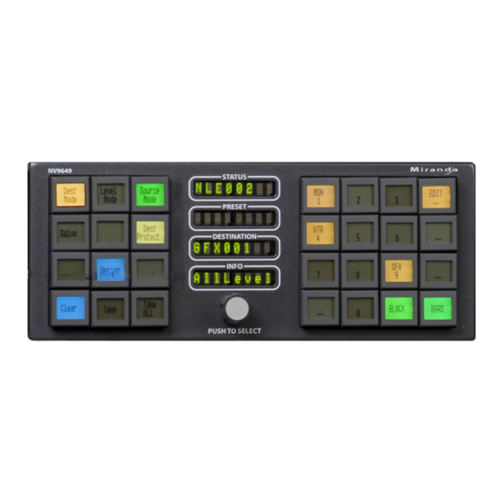
Introduction Display Fields Display Fields The display area has four separate 8-character display fields: These are their functions: • Status. The ‘Status’ field shows the source that is routed to the currently selected destination, which is identified in the ‘Destination’ field. If the operator is scrolling through levels in level mode, the ‘Status’... -
Page 17: Modes Of Operation
When the panel is in “server” mode, it operates in conjunction with a number of NV9648s. The NV9649 is the “server” and the NV9648s are the “clients. ” The NV9649 and the NV9648s combine to form, in essence, a larger panel — actually a cluster of many small control units. -
Page 18: Saved Client Assignments
NV9648 (7) 3 Panel Sections (7x) In this example, there are 21 control sections in addition to the controls of the NV9649. At any moment, the operator can route to 21 destinations. The operator can assign different destinations to the control units at any time. The function buttons in each individual control unit apply only to the destination assigned to that control unit. -
Page 19: Lcd Xy/Md' Mode
Setup Mode, on page 125 • Salvo mode — pressing a salvo button places the NV9649 in salvo mode, where it is expected that the operator will choose a salvo and then the ‘Take’ button to executes a salvo. (The duration of a salvo is indeterminate, but usually short.) See... -
Page 20: Special Modes
• Hold mode — when the operator has pressed a ‘Hold Preset’ button. See Selection Buttons, on page 65. Other NV9649 Functions The NV9649 can be configured to perform the following additional functions: • Previous source and free source. • System salvos. • Lock/protect/release for destinations. -
Page 21: Installation
Depending on your order, the NV9649 items that can ship include: • One or more NV9649 control panels. • One or two power supplies for each NV9649, with straps that secure the AC power cords to the power supplies. • One or more rack-mounting kits (NV9649-48-RMK). -
Page 22: Installation
The NV9649 is designed to mount in a 19© rack. Rack-mounting is not a requirement. The NV9649 is a 2RU half-width panel: you can install two of them side by side in a rack. Rack mounting (either one or two NV9649s) requires a rack mounting bracket such as the one in Grass Valley’s NV9649-48-RMK (rack-mounting kit). -
Page 23: Installing Software And Documentation
Valley if you need to obtain the latest version of this NV9000 configuration software. You may use the Panel IP Configuration Utility if you want to your NV9649 to have a static IP address (with respect to the NV9000) or to use DHCP. The panel, as it comes from the factory, defaults to DHCP. -
Page 24: Testing
These are points to consider after you install your NV9649 control panel(s): 1 Do the buttons illuminate? When an NV9649 powers up, one or more of its buttons are supposed to turn green or amber. Does it pass the panel test mentioned above? 2 When the NV9649 powers up and it is connected to the system controller, it should initialize completely. - Page 25 NV9649 User’s Guide The NV9649, by default, acquires its IP address through DHCP on the NV9000’s panel/router network. You can use the Panel IP Configuration Utility to force the panel to have a static IP address. If (in setup mode) you do not see your designated panel ID in the ‘Preset’ display field, you have either not initialized the panel or no configuration has been created for your panel in NV9000-SE Utilities.
- Page 26 Installation Testing...
-
Page 27: Configuration
NV9649 Panel Configuration Page(s) ........ - Page 28 The ‘Add Control Panel’ page appears: Choose “NV9649” from the ‘Type’ field. In the ID field, enter the panel ID you assigned to the panel while it was in setup mode. Give a name to the panel in the name field and select a user.
-
Page 29: Nv9649 Panel Configuration Page(S)
The file extension for an NV9649 configuration file is . Click ‘Next’ or ‘Finish’ to proceed. Return to the ‘Control Panels’ page to view your new entry. To edit an NV9649 configuration, either double-click its list entry or select the entry and then click ‘Edit Selected Control Panels’: You will then see the panel configuration page for the selected NV9649. -
Page 30: Common Page Features
Please refer to figures 4-1, 4-3, and 4-4, following. Panel Graphic At the top of the page is a graphic representation of the NV9649 panel. Above the graphic is a the pathname of the panel’s configuration file. (This file corresponds to what you are editing, which will eventually be sent to the NV9000.) -
Page 31: Common Configuration Tasks
User’s Guide Common Configuration Tasks The person configuring an NV9649 panel will want to consider how best to use the buttons to support the devices and routers in the router control system at hand. The task is non- trivial. In support of that effort, the configurer will do the following: •... -
Page 32: Button Functions
The NV9649 (the “server”) operates in conjunction with one or more NV9648s (the “clients”). The NV9649 can assign a destination to any of an NV9648’s 3 control sections and also assign sources to the source buttons of any of an NV9648’s control units. -
Page 33: Button Definitions Section
(The NV9648 has 3 sections that are independent control units. Each unit — having one display and 9 buttons — corresponds to a destination.) The NV9648s show current sources in their displays when the NV9649 is in source mode and show the sections’ destinations when the NV9649 is in destination mode. (Please refer to the NV9648 Users’... -
Page 34: Server Mode Panel Options
12 sets of client assignments. In the menu itself, a set of client assignments is called a “set-up. ” A NV9649 always has one default setup and may have up to eleven other named setups. (It is the upper left button that is assigned to the default setup.) By entering a name in the ‘Setup Name’... - Page 35 NV9649 User’s Guide These are the drop-down menu options for the panel in server mode: Panel Behavioral Panel Server In server mode, the panel interoperates with a number of Model Mode NV9648s, the NV9648s being configured as the “clients. ”...
- Page 36 Configuration Configuration Page for the Server Model The list of options differs according to whether you have checked the ‘Use Category & Suffix Pages’ option. These are the panel options when that option is not checked: Clearing the ‘Use Category & Suffix Pages’ option enables the use of category lists and the panel options includes an ‘Edit Category Lists’...
- Page 37 The underlying consideration is that takes are to be performed on the NV9648 clients only. • Disable destination assignments. If you check this option, the NV9649’s ability to assign destinations to NV9648 sections is disabled. • Quick preset take. If you check this option, when the operator presets a source, all ‘Take’ buttons in all NV9648 control units go high-tally.
-
Page 38: Category Lists And Category Pages
How to Create a Category List Follow these guidelines. 1 Go to the NV9649 configuration page in NV9000-SE Utilities. (The page must be for a configuration using the server model and for which the panel option ‘Use Category & Suffix Pages’ is unchecked.) - Page 39 NV9649 User’s Guide 2 Click the ‘Edit Category List’ button. The ‘Category Index Selection Editor’ window appears: On the left is a list of all categories defined in the NV9000 system. On the right is a list of the categories in the list you are defining. Initially the list for the panel configuration is empty.
-
Page 40: Category And Suffix Pages
Click any of these buttons to create or modify category pages and suffix pages. When you click the button, the appropriate configuration dialog appears. Suffix pages used by category pages under the ‘Panel Server’ model have no relation- ship to the global suffix pages available for NV9649 panels configured unde the LCD XY/MD model. - Page 41 NV9649 User’s Guide How to Create Category Pages The methods and configuration dialogs for source and destination categories are the same. Therefore this section describes the source category page editor only. What is said here also applies to the destination category page editor.
- Page 42 Configuration Category Lists and Category Pages Button Map This is a list of the 28 panel buttons at the right side of the panel that form the currently displayed button “page. ” The buttons are numbered from 0 to 27, thus: The button map shows the source categories that were assigned to the button array for the currently displayed button page.
- Page 43 NV9649 User’s Guide To define suffix pages, click ‘Edit Suffixes’ in the panel options section of the NV9649 configuration page. The ‘Suffix Page Editor’ dialog appears: List of Sources Button Map Suffix Drop-Down List Suffix Page List There are 4 main parts to this dialog: •...
- Page 44 Configuration Category Lists and Category Pages The button map shows the suffixes that were assigned to the button array for the currently displayed button page. You can use the arrow buttons in the middle of the category page list to select and show different button pages.
-
Page 45: Configuration Page For The Lcd Xy/Md Model
NV9649 User’s Guide Configuration Page for the LCD XY/MD Model This is a sample NV9649 panel configuration page for LCD XY/MD mode: Panel Image: Button Definition Section Page Table GPIO Definitions Panel Options Fig. 4-3: NV9649 Configuration Page (for LCD XY/MD Mode) -
Page 46: Characteristics Of Lcd Xy/Md Mode
Configuration Configuration Page for the LCD XY/MD Model There are 31 button function types for a panel in LCD XY/MD mode (not counting ‘Undefined’): Back Broadcast Category Chop Clear Preset Default State Destination Destination Lock Destination Protect Free Source Global Navigate Hold Level Map Menu... -
Page 47: Lcd Xy/Md Mode Panel Options
NV9649 User’s Guide This section displays a list of the individual pages of the tree structure. The button page at the top of the list (or root of the tree) is called “Default. ” During operation, category buttons can display device subpages when pressed. Those subpages are not explicitly definable in NV9000-SE Utilities. - Page 48 Configuration Configuration Page for the LCD XY/MD Model Default None After a reset, the panel displays no destination device. (This Destination is not recommended.) ‹device› The Panel uses the specified device as the destination after a reset. (The ‘Default State’ button also returns the panel to this destination.) Preset Monitor None...
- Page 49 NV9649 User’s Guide MD Data Automatic If a machine control (i.e., data) level is involved in a route, the Routing Mode system makes the route on the control level even if the control port is in use on the source or destination device. It breaks the previous control connection and then makes a new control connection for the route in progress.
- Page 50 Configuration Configuration Page for the LCD XY/MD Model Checkbox Options The checkbox options section is just below the panel options section, enclosed in the same region: A check in the box enables the option. Clearing the checkbox disables the option. By default, all the check box options are unchecked except ‘Src/Dst Immediate Take’...
- Page 51 After selecting many MD destinations (with ‘Hold’ mode on), it can be time-consuming and error-prone to find them all (and no others) to deselect them after a take. When you enable this option, the NV9649 does exactly that (and turns off hold mode). • Jump to multi-dest selection when switching to XY.
-
Page 52: Button Page List
Configuration Configuration Page for the LCD XY/MD Model Button Page List This section is the region below the button definition section. It lists the pages of the button tree. It has 3 columns: Page Number, Page Name, and “Link to Page Num(s). ” The button page at the top (or root) of the tree is called “Default. -
Page 53: Configuration Page For The Nv9609 Model
NV9649 User’s Guide Configuration Page for the NV9609 Model This is the default NV9649 panel configuration page for NV9609 mode: Panel Image Button Definition Section Panel Options GPIO Definitions Fig. 4-4: NV9649 Configuration Page (for NV9609 Mode) In NV9609 mode, the panel is standalone — independent of any NV9648s. -
Page 54: Characteristics Of Nv9609 Mode
NV9649. The NV9649’s knob can be used to emulate the ‘Page Up’ and ‘Page Down’ functions of the NV9609. The major difference between the NV9609 and the NV9649 is that the NV9649 has LCD buttons whereas the NV9609 has backlit buttons that do not have LCD legends. -
Page 55: Checkbox Options
NV9649 User’s Guide Preset Monitor None The preset source video is not sent to a monitor. ‹device› The preset source video for the selected destination appears on the specified monitor (device). Status Monitor None The current source video is not sent to a monitor. -
Page 56: Button Definitions
(if one was made) is retained even if the ultimately taken source does not require a tieline. The tieline is wasted. Button Definitions The NV9649 panel can be configured to operate under 3 behavioral models: • ‘Panel Server’ mode. • ‘NV9609 Panel’ mode. -
Page 57: Button Specification
The set of devices in a category can change over time (as the configuration database changes); the NV9649 device list changes also. The number and names of categories can also change over time and the NV9649 will track those changes too. Note: Certain button fields contain a colon (:) and number after the data in the field. - Page 58 Configuration Button Specification Button Color A pull-down menu where you can select a button color: amber, blue, green, grey, purple, red, or yellow: On the panel, each of the 7 defined colors has two brightness levels: “high-tally” and “low-tally. ” Buttons are dark if their functions are disabled.
-
Page 59: Button Functions For Server Mode
NV9649 User’s Guide Button Functions for Server Mode These are the button types available for NV9649 configurations under the server model: Type Description (under Server Mode) Assign When the panel is in destination mode, the button is used to assign a selected destination to an NV9648 control unit. - Page 60 Configuration Button Functions for Server Mode Type Description (under Server Mode) Category During operation, the button has 3 functions: 1 Display a source category’s device list when the panel is in source mode. 2 Display a destination category’s device list when the panel is in destination mode.
- Page 61 Menu This button puts the NV9649 panel in menu mode and displays a menu on the LCD buttons that provides access to a variety of panel options. The button is required only if you want the operator to have access to the menu.
- Page 62 The source selected by a source button is preset to be take to the current destination of the NV9649. (No takes can occur at the NV9649 if the panel option ‘Server Panel Destination Remove’ is checked in the configuration.) When you configure a source button, a drop-down menu appears: ‘Source...
-
Page 63: Button Functions For Lcd Xy/Md Mode
Makes the button undefined and inactive. On the actual panel, it will remain unused (dark). Button Functions for LCD XY/MD mode These are the button types available for NV9649 configurations under the LCD XY/MD model: Type Description (under LCD XY/MD Mode) Back The ‘Back’... - Page 64 Configuration Button Functions for LCD XY/MD mode Type Description (under LCD XY/MD Mode) Category Pressing the button displays a category’s device list. Note that category buttons in LCD XY/MD mode function differently from category buttons under server mode and NV9609 mode. There are differences in the configuration of these buttons too.
- Page 65 NV9649 User’s Guide Type Description (under LCD XY/MD Mode) Destination Selects a destination. When you configure a destination button, a drop-down menu appears: ‘Destination Device’ . Choose a device from the list. The ‘None’ entry is merely a placeholder. Do not choose ‘None’ .
- Page 66 The button definition has no fields to configure. Its legend is arbitrary. Menu This button puts the NV9649 panel in menu mode and displays a menu on the LCD buttons that provides access to a variety of panel options. The button is required if you want the user to have access to the menu.
- Page 67 NV9649 User’s Guide Type Description (under LCD XY/MD Mode) Navigate During operation, a navigate button selects and displays a “target” button page. During configuration, a navigate button presents a dialog in which you can enter details of the target page. After you do so, SE displays the target page’s buttons on the panel image and adds the subtree to the tree window in the lower left corner if it is not there.
- Page 68 Configuration Button Functions for LCD XY/MD mode Type Description (under LCD XY/MD Mode) Quick A quick source button selects a source and performs an immediate take. Source When you assign a quick source button, a drop-down menu appears in which you choose a source device. (The ‘None’ entry is merely a placeholder. Do not choose ‘None’...
- Page 69 NV9649 User’s Guide Type Description (under LCD XY/MD Mode) Selection Typically, at least one button page should provide a set of selection buttons. Operators press selection buttons to select levels (when the panel is in XY mode) or to select MD devices (in MD mode). Each selection button represents one level or one MD device.
- Page 70 Configuration Button Functions for LCD XY/MD mode Type Description (under LCD XY/MD Mode) Source Means “source is the master” and makes the source device the master. Master Otherwise, the destination is the master. It applies to machine control routes. The button is a toggle: Press it once to make the source the master (it goes high-tally);...
- Page 71 NV9649 User’s Guide Type Description (under LCD XY/MD Mode) XY Display The ‘X-Y Display’ button displays current route status — in X-Y mode, MD mode, or in limited X-Y mode. Pressing this button has no effect. It also displays other messages in other circumstances, as required.
-
Page 72: Edit Navigation Button' Dialog
This option creates a new page in the button tree. During operation, the navigation button you are creating will cause the NV9649 to display, or jump to, that page. The name of the page and the button caption are what you type in the three lines for the button caption. -
Page 73: Automatic Fill Options
The fill occurs in left-to-right top-down order, but in two sections: During operation, the navigation button will cause the NV9649 to display the first of the auto-fill pages. The operator uses the ‘Page Up’ and ‘Page Down’ buttons to page through the list. - Page 74 Configuration ‘Edit Navigation Button’ Dialog If you leave the ‘Starting with’ field blank, the page will list all devices. • ‘Manually Fill Devices’ . Specify the number of buttons you want to be assigned. The software creates as many subpages as are required to hold the buttons. The buttons are source buttons, but remain blank so that you can assign sources to them manually.
-
Page 75: Selection Buttons
NV9649 User’s Guide want. The new position will be indicated by a slightly heavier black line. The row you selected is re-positioned where the black line is when you release your mouse button. Selection Buttons Selection buttons are available only when the panel is configured under the LCD XY/MD model. -
Page 76: Selection
Configuration Selection Buttons Note that the maximum number of MD destinations is configured in multiples 8, from 8 to 512. Populating the MD Device List The ‘Edit Multi-Destination Device’ button appears when you are configuring a selection button. Click this button to get the ‘Multi-Destination Entry’ window. The window presents a list of all destinations on the left and a set of MD devices at the right. -
Page 77: Display Indexes
How to Configure MD Devices Follow these guidelines. 1 Go to the NV9649 configuration page of NV9000-SE Utilities. 2 Click any button in the panel image. In the button definition section, choose ‘Selection’ from the drop-down list. A ‘Display Index’ field and an ‘Edit Multi-Dest Devices’ button appear in the button... - Page 78 Configuration Multi-Destination Configuration 3 Click ‘Edit Multi-Dest Devices’ . The multi-destination entry editor appears: On the left is a list of all destinations defined in the NV9000 system. On the right is a table of the MD destinations you are defining. The number of rows in this table is equal to the maximum number of MD destinations your configuration allows.
-
Page 79: Md Destination Options
Uncheck the ‘User Selectable’ box if you want to prevent the operator from taking a source to this destination. Button Functions for NV9609 Mode These are the button types available for NV9649 configurations under the NV9609 model: Type Description (under NV9609 Mode) - Page 80 Configuration Button Functions for NV9609 Mode Type Description (under NV9609 Mode) Category The button selects a device category. The button can operate in source mode or destination mode. (Source category buttons operate in level mode; destination category buttons do not.) During configuration, you can specify a source category for the button, a destination category, and a suffix.
- Page 81 “Force Release” enabled. The button definition has no fields to configure. Its legend cannot be changed. The NV9649 provides no explicit indication, during operation, whether a destination is locked or unlocked. Destination The button places the panel in destination mode. Category selections in Mode destination mode select destination devices.
- Page 82 The button definition has no fields to configure. Its legend cannot be changed. The NV9649 provides no explicit indication, during operation, whether a destination is locked or unlocked. Free Source The button selects a pre-defined phantom device that can be used to release or “free”...
- Page 83 Description (under NV9609 Mode) Menu This button puts the NV9649 panel in menu mode and displays a menu on the buttons that provides access to a variety of panel functions. Without the button, the operator has no access to the menu functions.
- Page 84 Configuration Button Functions for NV9609 Mode Type Description (under NV9609 Mode) Page Up The button scrolls up. Scrolling devices within a category: ‘Page Up’ moves to the next higher device in the category’s device list. (Example: if the current device is VTR_12, the next higher device would probably be VTR_13, subject to the device definitions in the NV9000 configuration.) Scrolling devices is possibly only when a category selection is in progress.
- Page 85 NV9649 User’s Guide Type Description (under NV9609 Mode) Salvo A salvo button places the panel in salvo mode. In salvo mode, the operator scrolls through the salvo list configured for the panel (as a panel option) to select a salvo. When the desired salvo is selected, the operator presses a ‘Take’...
-
Page 86: Tally (Gpio) Window
It has two sections: inputs and outputs. By clicking on one of the input or output buttons, you can configure the input or output. (The NV9649 has no actual tally buttons. These buttons represent the DB25 connector at the rear. The buttons are present in the configuration page to allow you to configure the tally interface.) -
Page 87: Names
1 Choose ‘Control Panels’ from the ‘Configuration’ pane. Then click ‘Add Control Panel’ . 2 In the ‘Add Control Panel’ page, complete the details as you would for a panel: The panel type is NV9649. Specify a panel ID, a name, and choose ‘New’ in the options section. -
Page 88: Referencing A Navigate Template
Configuration Referencing a Navigate Template When you check the option, an addition ‘Suffix Page’ field appears. Choose one of your defined suffix templates in the drop-down list. The suffix page appears in the panel configuration’s button page list: Suffix page ... -
Page 89: Composing Suffix Templates
NV9649 User’s Guide Choose a navigate template in that field. The global navigation page and any of its subpages appears in the panel configuration’s button page list: Global navigation page(s) The global navigation pages are copies made from the navigate template. They are not the template or a link to the template. -
Page 90: Template Changes
‘Push changes to panel configs’ on the configuration page. When you do, the configuration software adjusts all NV9649 panel configurations to use the modified suffix template. This might override changes you have made to the copy of the suffix page in some panel configuration. -
Page 91: Operation
This chapter is intended specifically for the NV9649 panel operator. Summary As an NV9649 operator, you will be confronted initially with a relatively small and simple panel — 28 buttons, four 8-character displays, and a knob (that you can rotate and push). -
Page 92: Buttons And Button Legends
Buttons and Button Legends Each of the NV9649’s 28 LCD buttons has 1, 2, or 3 lines of text, 8 characters per line. When there are one or two lines of text, the characters are large; when there are 3 lines of text, the characters are smaller. -
Page 93: Behavioral Models
When the panel is in “server” mode, it operates in conjunction with a number of NV9649s. The NV9649 is the “server” and the NV9649s are the “clients. ” The NV9649 and the NV9649s combine to form, in essence, a larger panel — actually a cluster of many small control units. -
Page 94: Saved Client Assignments
Saved Client Assignments Every time an operator assigns a destination to an NV9649 client or assigns a source to a source button of a client, those assignments are recorded within the NV9000 system controller. -
Page 95: Lcd Xy/Md Model
NV9649 User’s Guide LCD XY/MD Model When the panel is in LCD XY/MD mode, it operates standalone, without regard to any NV9649s, and has a moderately richer function set than a panel in the other two modes. The panel’s buttons can be used in a hierarchical fashion: pressing a ‘navigation’ button causes the panel to display a new set of configured button functions, called a “button... -
Page 96: Secondary Modes
In this mode, you can preset the NV9649’s panel ID and perform a few diagnostic tasks. • Salvo mode — pressing a salvo button places the NV9649 in salvo mode, where it is expected that the operator will choose a salvo and then press a ‘Take’ button to executes a salvo. -
Page 97: Levels
NV9649 User’s Guide It is in the panel’s ‘Manage Config’ sub-menu (if the panel has a menu button) that an operator can select one of the defined setups. This sub-menu uses the 12 buttons at the left side of the panel. The upper left button is always reserved for the default setup. Some of the other 11 buttons might be blank. -
Page 98: Level Grouping
(Other panels can show level group names.) We discuss level groups — a feature of the router control system — only to state that the NV9649 does not have support for level groups. Hold Under the LCD XY/MD model, hold mode (and hold buttons) apply in both X-Y mode and multi-destination mode. -
Page 99: Lock, Protect, And Release
NV9649 User’s Guide NV9649 category buttons can represent a source category or a destination category. When you press a category button to begin device selection, the panel displays a list of all devices in that category. You can scroll through multiple pages of devices using ‘Page Up’ and ‘Page Down’... -
Page 100: Name Sets
• You have selected a destination and press a ‘Quick Source’ button (or a ‘Src/Dst’ button). The take occurs immediately. • There is a default destination (or a destination assigned by an NV9649) and you select a source. A ‘Take’ button lights and you press the ‘Take’ button. -
Page 101: Making Broadcast Routes
NV9649 User’s Guide Making Broadcast Routes Follow these steps to broadcast control signals: 1 Ensure that the panel is in “source is master” mode. It is either in “source is master” mode by default or you must press a ‘Source is Master’ button to activate the mode. -
Page 102: Semi-Automatic Data Routing
You can cancel the control-level take by pressing a button other than ‘Take’ . Button Functions The NV9649 has 3 behavioral models. The sets of button functions differ in the 3 models. Buttons for the Server Model There are 17 button function types for a panel in server mode (not counting ‘Undefined’):... -
Page 103: Broadcast
NV9649 User’s Guide Destinations and sources assigned with this function are preserved (in the system controller) even when power fails. Destination and source assignments can be grouped into different sets to be used perhaps by different users or at different times of the day, or for any reason. -
Page 104: Clear
ID, or by a forced release at any panel. The NV9649 provides no explicit indication, during operation, whether a destination is locked or unlocked. Destination Mode The button places the panel in destination mode. -
Page 105: Menu
You may lock a protected destination, but you cannot change a locked destination to a protected destination directly. You must first unlock it. The NV9649 provides no explicit indication, during operation, whether a destination is locked or unlocked. Menu A ‘Menu’... -
Page 106: Src/Dst Mode
Take All Use the ‘Take All’ button to take a source you have selected to the destinations of all the NV9649 control units. Undefined An undefined button cannot be used and appears dark (unlit) on the panel. The term “undefined”... -
Page 107: Broadcast
If, for example, the devices in the category number from 1 to 7, buttons for the digits 8 and 9 will be disabled. A typical NV9649 configuration has a “keypad” — possibly on a suffix page — with which you can enter device indexes or suffixes. Keypad buttons are actually category buttons. Any keypad button can also be a source category button and a destination category button. -
Page 108: Chop
The default button text is “Clear Preset” but the button might have any legend. Default State This button returns the NV9649 to its most recent power-up state. You may consider this button an emergency button or a “soft reset” button. -
Page 109: Destination Protect
You may lock a protected destination, but you cannot change a locked destination to a protected destination directly. You must first unlock it. The NV9649 provides no explicit indication, during operation, whether a destination is locked or unlocked. Free Source The button selects a pre-defined phantom device that can be used to release or “free”... -
Page 110: Level Map
Operation Buttons for the LCD XY/MD Model MD Mode In MD mode, turning hold mode on allows you to select more than one destination button at a time. When you select a source, the source applies to all selected (high-tally) destinations. -
Page 111: Name Set Toggle
NV9649 User’s Guide By pressing certain buttons, you makes menu selections and enter data (such as panel ID) or change brightness values. When the panel is in menu mode, you must press the ‘Menu’ button to cycle through the functions of the menu. See Menu Mode on page 116. -
Page 112: Panel Lock
‘Preset Release’ button and tell you who locked or protected the source. You can release it if your panel has “forced release” enabled. (Note that you cannot lock or protect sources with the NV9649.) Press the ‘Preset Release’ button to release the source. -
Page 113: Salvo
NV9649 User’s Guide Normally, the button text is the source’s mnemonic, but the configurer can assign any text to the button. Salvo The button presets a salvo. (Subsequently pressing the ‘Take’ button actually executes the salvo.) The default button text is the salvo name but the button can have any legend. -
Page 114: Source
Operation Buttons for the LCD XY/MD Model If you have enabled ‘Hold’ mode, 1 Select one or more MD devices. Scroll the MD device display as needed. 2 Select a source. 3 Repeat steps 1 and 2 until your presets are complete. 4 Press ‘Take’... -
Page 115: Take
NV9649 User’s Guide Pressing the ‘Source is Master’ button turns off the ‘Broadcast’ button and vice versa. Take In normal mode, a take button routes the preset source to the selected destination on selected level or levels. In salvo mode, a take button executes a selected salvo. -
Page 116: Broadcast
Category buttons that have only a suffix configured are disabled until a category becomes selected. A typical NV9649 configuration has a “keypad” with which you can enter device indexes or suffixes. Keypad buttons are actually category buttons. Any keypad button can also be a source category button and a destination category button. -
Page 117: Chop
ID, or by a forced release at any panel. The NV9649 provides no explicit indication, during operation, whether a destination is locked or unlocked. -
Page 118: Destination Protect
You may lock a protected destination, but you cannot change a locked destination to a protected destination directly. You must first unlock it. The NV9649 provides no explicit indication, during operation, whether a destination is locked or unlocked. Free Source The button selects a pre-defined phantom device that can be used to release or “free”... -
Page 119: Menu
NV9649 User’s Guide To effect a single-level take in level mode, (1) scroll to choose a level, then (2) start the selection of a source (using a category button) while in level mode. The panel exits level mode immediately after you start the source selection. Complete the source selection. -
Page 120: Panel Lock
Operation Buttons for the NV9609 Model would probably be VTR_13, subject to the device definitions in the NV9000 configuration.) Scrolling devices is possibly only when a category selection is in progress. • Scrolling salvos in salvo mode: ‘Page Up’ moves to the salvo with the next higher index in the panel’s salvo list. -
Page 121: Source Mode
NV9649 User’s Guide Selecting a source activates the ‘Take’ button, which you must press to complete the route. Source Mode The button places the panel in source mode. Category selections in source mode select source devices. Category buttons that are not source categories become disabled in source mode. -
Page 122: Undefined
Procedure A — Preset a Source Using the Knob To preset a source in the preset display of the NV9649 (server): 1 Ensure that the NV9649 is in source mode. Press a ‘Source Mode’ button or press a ‘SRC/DST Mode’ button when the panel is in destination mode. -
Page 123: Procedure B - Preset A Source Using A Keypad
Procedure B — Preset a Source Using a Keypad To preset a source in the preset display of the NV9649 (server): 1 Ensure that the NV9649 is in source mode. Press a ‘Source Mode’ button or press a ‘SRC/DST Mode’ button when the panel is in destination mode. -
Page 124: Procedure E - Takes Using Source Buttons
Procedure G To perform a ‘Take All’: 1 Ensure that the NV9649 is in source mode. Press the ‘Source Mode’ button or press a ‘SRC/DST Mode’ button if the panel is in destination mode. 2 Use procedure A or procedure B described above to select (i.e., preset) the desired source. -
Page 125: Procedure I - Perform Device Selection Using Category Pages
Procedure I — Perform Device Selection using Category Pages An NV9649 panel in server mode can be configured to allow operators to perform device selection using category pages. When the NV9649 is so configured, it shows ‘CatPages’ in the ‘Info’... -
Page 126: Menu Mode
Press any other button while the panel is in salvo mode to return the panel to its normal mode. Menu Mode The NV9649 enters menu mode if it has a menu button and you press the menu button. The menu uses the buttons on your panel. The legends and functions of these buttons in normal operating mode do not apply while the panel is in menu mode. -
Page 127: User
Press Save to accept your change to the panel ID and leave the submenu. ‘Manage Configs’ The NV9649 (as the server) and the NV9649s (as the clients) are designed so that when the panel operator uses the NV9649’s ‘Assign’ button to assign destinations or sources to the... - Page 128 The assignments to the clients are saved in the system controller to which the NV9649 and the NV9649s are connected. We call the set of all client assignments a “setup. ” The NV9649 and the NV9649s are further designed so that you can define up to 12 different named setups.
- Page 129 ‘Clear Set-Up’ This button (in the ‘Manage Configs’ menu) presents the ‘Clear’ menu. The ‘Clear’ menu lets you revert all the NV9649 clients to their configured assignments with respect to one of the named setups. (Other named sets remain unaffected.) The “configured assignments”...
-
Page 130: Reboot
Subsequent source and destination assignments are recorded in the current setup and other setups are not affected. Reboot The ‘Reboot’ button of the menu lets you restart the NV9649 and all the NV9649 clients associated with it. If you press the reboot button, the menu presents a cautionary sub-menu: PANEL ID CANCEL RE–BOOT... -
Page 131: Panel Id
NV9649 User’s Guide Panel ID The panel ID sub-menu is the first sub-menu that appears when you first press the menu button: P a n e l I D Menu button, in MENU these examples _ _ _ _ 6 4 9 1 The panel shows the panel ID in the ‘Preset’... -
Page 132: Software Versions
Operation Software Versions Software Versions The fifth submenu displays the software version: MENU S V 0 9 2 1 - 0 The sixth submenu displays the boot version: B S V 0 6 3 9 MENU – 0 2 0 0 0 0 The seventh submenu displays the application version: A S V 0 0 0 0 MENU... -
Page 133: Menus Under The Lcd Xy Model
NV9649 User’s Guide Menus under the LCD XY Model This is the menu that appears when you press a menu button and the panel is operating under the LCD XY model: SOFTWARE SOFTWARE USER USER PANEL PANEL VERSIONS VERSIONS LCD LCD... -
Page 134: Panel
Operation Panel Panel The panel submenu is available under all 3 behavioral models. The panel submenu displays facts about the panel: PANEL ID PANEL ID PANEL PANEL IP ADDR IP ADDR NAME NAME 192.168. 192.168. 6493 6493 L649 L649 104.84 104.84 SVR NAME... -
Page 135: Setup Mode
Buttons, on page 141 for a better color chart. Setup Mode Setup mode occurs when the NV9649 is disconnected from its network and is freshly powered up. In setup mode, you can set or change the panel ID, identify the software version, and perform a test of the panel’s buttons. -
Page 136: Software Versions
Operation Software Versions Now press the ‘Enter Panel ID’ button. The buttons on the left side of the panel light up and form a numeric keypad: N V 9 6 4 9 PANEL ID PANEL ID 6491 6491 P a n e l I D _ _ _ _ _ 1 2 3 CLEAR CLEAR... - Page 137 Pressing the exit button will terminate the button test and return you to the initial display of setup mode. At this point — if you have a assigned your NV9649 a suitable panel ID — you may connect your NV9649 to the panel network of your NV9000 system.
- Page 138 Operation Panel Test...
-
Page 139: Gpio
Tally devices you connect to inputs can trigger events — through the NV9649 — in the router control system. The router control system can trigger events that — through the relays in the NV9649 — switch your tally devices. -
Page 140: Output
When a condition (defined for the relay) occurs, the router control system notifies the NV9649 which then opens or closes the relay. The relay switches the customer’s circuit on or off. (It does not power the circuit. Customers must provide their own power.) GPIO Configuration Concepts These are the I/O characteristics of the NV9649’s tally interface:... -
Page 141: Configuring Outputs
Click on a button under ‘Inputs’ to configure one of the 8 tally inputs. There are no actual GPIO buttons on the NV9649 control panel. Configuring Outputs Clicking an output button (one of 4) displays a “Relay Rule” dialog for the output:... - Page 142 The actual logic takes place in the router control system, based on the state of the NV9649 inputs and other system-wide events. The router control system sends signals to the NV9649 instructing it to open or close its relays.
-
Page 143: Configuring Inputs
Its 8 inputs can be switched on or off by your external devices. When an input transitions on or off, the NV9649 can respond with one of 4 actions, such as executing a salvo. (It is the system that actually executes the salvo.) - Page 144 GPIO GPIO Summary...
-
Page 145: Technical Details
NV9649 Specifications ........ -
Page 146: Nv9649 Specifications
DC Output Fig. 7-1: The power output has Molex 4-pin plug. See Power Cord Retention on page 142. NV9649 Specifications Specifications for the NV9649. Specification Detail Dimensions Height: 3.47 in(88.1 mm), fits EIA 2 RU (3.5 in or 88.9 mm), Width: 8.7 in (221.0 mm). -
Page 147: Environmental Specifications
Destination: the configured default. Buttons: low-tally is 40% brightness by default and stays at its most recent setting. Configuration Page The initial NV9649 configuration has no buttons defined. The default panel options are: Behavioral model: LCD XY/MD mode. Default mode: Multi-destination mode. -
Page 148: Drawings
[88.1] Fig. 7-2: Front View of the NV9649 3.41 [86.6] 8.7 [221.0] 2.46 [62.6] 3.47 [88.1] Fig. 7-3: Rear and Side View of the NV9649 This is the NV9649’s rack mounting filler plate: 3.47 [88.1] 8.7 [221.0] 2.213 [56.2] Fig. 7-4: NV9649 Rack Mounting Filler Plate... - Page 149 NV9649 User’s Guide This drawing provides overall dimensions of the NV9649’s rack mounting bracket: Fig. 7-5: NV9649-48-RMK Rack Mounting Bracket...
- Page 150 Technical Details Drawings For reference, this is a view of the NV9648: 8.7 [221.0] 3.47 [88.1] Fig. 7-6: Front View of the NV9648...
-
Page 151: Misc. Topics
Misc. Topics Chapter 8 provides the following: Summary LCD Buttons ............... . . 141 Power Cord Retention . -
Page 152: Power Cord Retention
Misc. Topics Power Cord Retention Power Cord Retention Use the supplied retention strap to keep the AC power cord firmly connected to the power supply. Follow these steps to use the strap: 1 Firmly insert the AC power cord into the power supply. Examine the last figure in this section to see how the strap should be applied. -
Page 153: Ordering Information
NV9649 User’s Guide Ordering Information These are the NV9649 components: PS0001 12V power supply, 4-pin Molex connector, with cord, and cord retention strap. NV9649 NV9000 control panel. 30 button, 2RU, XY/MD, hierarchical. WC0053 Optional breakout cable for the tally interface... - Page 154 Misc. Topics Ordering Information...
-
Page 155: Glossary
AES router, and time code on input port 8 of the time code router. GPIO General Purpose Input and Output. A generic term for the NV9649’s tally interface. The tally interface is called the “GPI Interface” at the rear of the NV9649. - Page 156 Glossary Source/ The term “source device” is used interchangeably with “source” and the term “destination Destination device” is used interchangeably with “destination. ” A source is a device that is connected to one or more input ports. A destination is a device that is connected to one or more output ports.
-
Page 157: Index
Index Brightness, LCD ......82 Broadcast ........60 Broadcast (button) 49, 53, 69, 90–91, 93, 97, 105–... - Page 158 Button tree ........82 NV9649 ....... . . 17 Button types .
- Page 159 ......40 NV9649, rear view ..... . 138 source is master .
- Page 160 ....100 NV9649, rear view ..... . . 138 initialize the NV9649 .
- Page 161 NV9649 User’s Guide LCD brightness ..... . . 51, 56, 82 software version ......122 LCD buttons .
- Page 162 Page up (button) ..57, 74, 82, 97, 102, 106, 109 NV9649 ......2, 11–13, 17 Pane, configuration .
- Page 163 Return from breakaway status after timeout NV9649, rear ......4 (option) ......46 power cord retention .
- Page 164 Index Single-destination mode ....67 Software ........13 Software version (submenu) .
- Page 165 NV9649 User’s Guide X-Y display (button) .....61, 105 X-Y mode 37, 41, 60–61, 65–66, 82, 100, 103, 105, 145– ....... . 146 WC0053 .
- Page 166 Index...
-
Page 167: Contact Us
1-800-547-8949 (US and Canada) or +1 530 478 4148. To obtain a local phone number for the support center nearest you, please consult the Contact Us section of Grass Valley’s website ( www.grassvalley.com An online form for e-mail contact is also available from the website.
Need help?
Do you have a question about the NV9649 and is the answer not in the manual?
Questions and answers