Table of Contents
Advertisement
Quick Links
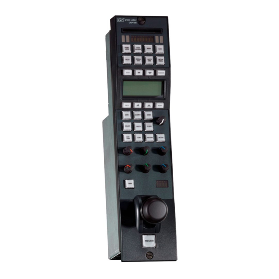
OCP 400
Operational Control Panel
User's Guide
3922 496 49931 August 2014 v12.0
CAMERA 4
PANEL
WHITE
BARS
CALL
LOCK
BALANCE
FILES
RECALL
AUTO
SETUP
EXIT
TOGGLE
PREV.
NEXT
SKIN
GAMMA
KNEE
COLOR
BLACK
FLARE
EXP.
GAIN
FILTERS
DETAIL
TIME
GAMMA
GAMMA
SKIN
GAIN
SKIN
FLARE
FLARE
BLACK
FREE
EXTENDER
PREVIEW
Software v28
Advertisement
Table of Contents

Related Manuals for GRASS VALLEY OCP 400


Summary of Contents for GRASS VALLEY OCP 400
- Page 1 WHITE BARS CALL LOCK BALANCE FILES RECALL AUTO SETUP EXIT TOGGLE PREV. NEXT SKIN GAMMA KNEE COLOR BLACK FLARE EXP. GAIN FILTERS DETAIL TIME GAMMA GAMMA SKIN GAIN SKIN FLARE FLARE BLACK FREE EXTENDER PREVIEW OCP 400 Operational Control Panel...
-
Page 2: Declaration Of Conformity
Liable to technical alterations in the course of further development. Trademarks Grass Valley, LDX Series and derivatives are trademarks of Belden Inc. or Grass Valley. All other tradenames referenced are service marks, trademarks, or registered trademarks of their respective companies. -
Page 3: Table Of Contents
Variable matrix and shading ........28 OCP 400 Operational Control Panel User’s Guide (v12.0) - Page 4 Specifications for OCP 400 ........
- Page 5 End-of-life product recycling Grass Valley’s innovation and excellence in product design also extends to the programs we’ve established to manage the recycling of our products. Grass Valley has developed a comprehensive end-of-life product take back program for recycle or disposal of end-of-life products.
-
Page 6: Important Information
Caution Do not plug in the power cable connector into the Ethernet connector. Plugging the power cable connector into the Ethernet connector of the OCP 400 will damage the connector. Safety Summary This informaton is intended as a guide for trained and qualified personnel who are aware of the dangers involved in handling potentially hazardous electrical/electronic equipment. -
Page 7: Chapter 1 - Introduction
Chapter 1 Introduction 1.1 Application The OCP 400 is a compact operational control panel for all Grass Valley cameras. The user interface is designed for convenience, with menu accessible functions for detailed set-up and a clear display of functions and values. -
Page 8: Using This Guide
Chapter 1 - Introduction 1.3 Using this guide The OCP 400 can control many different types of camera. This guide includes all possible menu items and functions. Depending on the type of camera to which the OCP is connected, not all of these items and functions may be available. The values available are also camera dependent.The menu system only displays the relevant items. -
Page 9: Location Of Controls
- push to see a selected camera signal on a preview monitor. - press simultaneously with the PREVIEW preview knob for six seconds to reset the OCP . OCP 400 Operational Control Panel User’s Guide (v12.0) -
Page 10: Using The Ocp Controls
– The upper Red, Green and Blue assignable rotary controls vary either: – the gain levels of the red, green and blue signals individually (default), – the gamma levels of the red, green and blue signals individually, or – the skin contour colours. OCP 400 Operational Control Panel User’s Guide (v12.0) -
Page 11: Joystick
FREE button is pressed, the value of the master black level is displayed for five seconds. The Extender indication lights when the range extender function of the lens is selected. OCP 400 Operational Control Panel User’s Guide (v12.0) -
Page 12: Panel Lock Button
FLARE FLARE FLARE FLARE FLARE FLARE BLACK BLACK BLACK BLACK FREE FREE FREE FREE EXTENDER EXTENDER EXTENDER EXTENDER PREVIEW PREVIEW PREVIEW PREVIEW Darker color means that the button or control is locked. OCP 400 Operational Control Panel User’s Guide (v12.0) -
Page 13: Bars Button
The menu panel buttons are illuminated to indicate their state: • not lit: no function for that button • low light: function available; push to change or to assign to rotary control. • bright light: function is assigned to rotary control. OCP 400 Operational Control Panel User’s Guide (v12.0) - Page 14 There are several ways of opening a menu page. You can use: – the SETUP button – the FILES button – the RECALL STD. button – the video parameter buttons Push an activated button to exit that particular menu function. OCP 400 Operational Control Panel User’s Guide (v12.0)
-
Page 15: Chapter 2 - Configurations
Chapter 2 Configurations 2.1 Studio configuration One or more OCP 400 control panels are connected to the C2IP camera control network. The IP address and other options for the Ethernet connection can be set up in the OCP Setup menu. -
Page 16: Dual Camera Configuration
OCP 400 2.3 Single camera configuration In local mode, the OCP 400 is directly connected to the serial RS-232 connector at the front of the camera. Both the camera and the OCP 400 must be powered locally. Video signals are available at the camera’s adapter. - Page 17 Chapter 2 - Configurations OCP 400 Operational Control Panel User’s Guide (v12.0)
- Page 18 Chapter 2 - Configurations OCP 400 Operational Control Panel User’s Guide (v12.0)
-
Page 19: Chapter 3 - Setup
☞ Note Note It is recommended to use Grass Valley’s LDK 5903 power supply unit with the OCP 400. 3.2 Checking system status To check that XCU/Base Station and camera are connected correctly go to the Diag menu in the setup menu. -
Page 20: Setting Up The Ocp
– The first page of the OCP setup menu appears. Use the NEXT button to find the page with the item you wish to change and then select this item with its correpsonding selection button. OCP 400 Operational Control Panel User’s Guide (v12.0) - Page 21 Low/High / High/Low / Open/High page 6 preview connector. / High/Open — — Lock+Free Defines which part of the panel Upper, Joystick, Matching stays locked when Free button is pushed (in Locked mode). OCP 400 Operational Control Panel User’s Guide (v12.0)
-
Page 22: Setting The Ocp Control Level
The OCP can be assigned to an XCU/Base Station - camera combination by moving to the CamNum item of the OCP setup menu. Select the camera number of the camera that you want to control using the assignable rotary control. Press SELECT to confirm. OCP 400 Operational Control Panel User’s Guide (v12.0) -
Page 23: Ip And Ethernet Configuration
IP address 4th byte 1..254 (2) Menu Selections Function Level Possible values Ethernet Eth Speed Ethernet speed setting 10 Mbit, 100 Mbit, Auto Config Duplex Ethernet duplex-mode setting Full, Half, Auto page 1 — — OCP 400 Operational Control Panel User’s Guide (v12.0) -
Page 24: Display And Button Brightness
XCU/Base Station default files. The camera parameters and their values that are shown on the OCP depend on the camera connected to OCP . If you select a different camera number, a different set of parameters and values can appear. OCP 400 Operational Control Panel User’s Guide (v12.0) -
Page 25: Setting Up The Xcu/Base Station
The menu appears on the XCU/Base Station text and monitoring output. Menu Selections Function Level Possible values BS menu Navigate ‘up’ in the BS menu control Down Navigate ‘down’ in the BS menu S Select Activate ‘select’ in the BS menu S OCP 400 Operational Control Panel User’s Guide (v12.0) -
Page 26: Setting Up The Camera
Sets maximum User level 0, 1, 2, 3, 4 setup OnAir LAMP Front On Air indicator On, Off page 8 OnAir LVL On Air indicator level 0..99 Power Camera remote power On, Off OCP 400 Operational Control Panel User’s Guide (v12.0) - Page 27 Noise Red Selects Noise Reducer Mode Off, 1, 2, 3 Menu Selections Function Level Possible values VF MENU Up menu (also with rotary) control Down Down menu (also with rotary) Select Select OCP 400 Operational Control Panel User’s Guide (v12.0)
-
Page 28: Variable Matrix And Shading
(for blue) B-PAR H Sets the horizontal parameter 0..99 (50) (for blue) B-SAW V Sets the vertical sawtooth value 0..99 (50) (for blue) B-PAR V Sets the vertical parameter (for 0..99 (50) blue) OCP 400 Operational Control Panel User’s Guide (v12.0) -
Page 29: Chapter 4 - Operation
✎ Even when auto iris is activated the manual control can still be used to vary the iris opening by +1 or - 1 F-stop. OCP 400 Operational Control Panel User’s Guide (v12.0) -
Page 30: Changing Camera Video Parameters
Programmable functions Up to 6 functions can be assigned in the OCP setup menu (refer to “Setting up the OCP” on page 20). These functions are accessed from the monitoring pages. OCP 400 Operational Control Panel User’s Guide (v12.0) -
Page 31: Monitoring
EXIT TOGGLE Knee slope and Skin detail Knee On BlkStr 54 point values usage Sl85 pt80 Skin 1+2 Gamma V76 SD 16:9 Gamma Video aspect value ratio PREV NEXT OCP 400 Operational Control Panel User’s Guide (v12.0) -
Page 32: Programmable Function
5 ☞ ☞ Note Note Programmable functions that are disabled in the OCP setup menu are not shown. When all functions on a page are disabled, the entire page is not shown. OCP 400 Operational Control Panel User’s Guide (v12.0) -
Page 33: Transmission Diagnostics
XCU/Base Station Signal quality from camera to PREV NEXT XCU/Base Station ☞ ☞ Note Note Refer to the user guide of your camera or transmission system for more information about these diagnostic indications. OCP 400 Operational Control Panel User’s Guide (v12.0) -
Page 34: Using Files
Store Scene File 1 Ready, Failed files STORE 2 Store Scene File 2 Ready, Failed page 2 STORE 3 Store Scene File 3 Ready, Failed STORE 4 Store Scene File 4 Ready, Failed OCP 400 Operational Control Panel User’s Guide (v12.0) -
Page 35: Ocp File Management
CAMERA CARD Before OCP File Management can be used you need to format an OCP storage card. Empty cards can be obtained from Grass Valley in a set of 10 cards (LDK 5210). Follow these steps for to format a card: Insert the card into the slot at the top of the OCP and push the FILES button. -
Page 36: Fast Recall Menu
Go to the down Delete/Rename menu Select RECALL to recall the settings in the selected scene file. Select STORE to store the current settings of the camera into the selected scene file. OCP 400 Operational Control Panel User’s Guide (v12.0) - Page 37 Select OK to use the new filename. The file will be added to the card and the current settings are stored in this file. • Select CANCEL to cancel the operation and return to the Recall/Store menu. ☞ ☞ Note Note File names can have up to ten characters. OCP 400 Operational Control Panel User’s Guide (v12.0)
-
Page 38: Delete/Rename Menu
A scene file can have a Read Only (R) status and a Read/Write (R/W) status. EXIT TOGGLE Scam1 ATTRIB SCam2 CardScene1 <new file> PREV NEXT Go to the Copy files menu ☞ ☞ Note Note Read/Write attributes of a camera scene file can not be changed. OCP 400 Operational Control Panel User’s Guide (v12.0) -
Page 39: Copy Files Menu
Select FORMAT to format a card. Select RENAME to enter a new name for the card. Refer to to Recall/Store menu for the naming procedure. EXIT TOGGLE OCP 400 CARD ocp card #1 Files: 5 Free: 89% FORMAT RENAME PREV NEXT OCP 400 Operational Control Panel User’s Guide (v12.0) -
Page 40: Partial File Recall
– Select either a factory or a customer file for recall. – Select RECALL. Menu Selections Function Level Possible values Recall RECALL Recall standard file Standard STD CUST/ Select factory or customer file Factory, Custom FACT to recall OCP 400 Operational Control Panel User’s Guide (v12.0) -
Page 41: Adjusting Video Parameters
Adjust Skin 1 Color B Level 0..99 WIDTH1 R Adjust Skin 1 Width R Level 0..99 WIDTH1 B Adjust Skin 1 Width B Level 0..99 SET SKIN1 ViewInsert Skin view insertion point Main, BS Mon page 3 OCP 400 Operational Control Panel User’s Guide (v12.0) -
Page 42: Setting Skin Detail
The skin detail function is not limited to a particular color and so can also be used to achieve various effects in selected color areas. For example, decrease the detail level of a OCP 400 Operational Control Panel User’s Guide (v12.0) -
Page 43: Gamma Button
When variable gamma is selected and the NEXT button is pressed, the upper row of rotary controls are assigned to changing the gamma R, G and B values. The GAMMA lights light. OCP 400 Operational Control Panel User’s Guide (v12.0) -
Page 44: Knee Button
100%..118% level after compression. Knee WhiteClip Switches White Clipper on or off B On, Off page 3 Wclip Lvl Sets White Clipper Level 0..99 Knee Mode Selects Knee Mode PwrCurves, Compat OCP 400 Operational Control Panel User’s Guide (v12.0) -
Page 45: Color Button
Go to the color correction menu Chroma Switches Chroma on or off On, Off Color Protect Switches Color Protect on or off On,Off page 3 Level Selects Color Protect Level 0% .. 150% OCP 400 Operational Control Panel User’s Guide (v12.0) -
Page 46: Black Button
— 4.5.7 Flare button – Press the FLARE button to open the flare menu. – The lower row of rotary controls are assigned to changing the flare values. The FLARE lights light. OCP 400 Operational Control Panel User’s Guide (v12.0) -
Page 47: Exposure Time Button
VAR MGain Sets variable Master Gain x, xdB GAIN - Decreases gain -, 0, +, ++, +++ StudioMode On, Off 4.5.10 Filters button – Press the FILTERS button to open the filters menu. OCP 400 Operational Control Panel User’s Guide (v12.0) - Page 48 Depth R Set red color depth 0..99 [LDK 500 only] Depth G Set green color depth 0..99 Depth B Set blue color depth 0..99 Soft Focus Filter menu (LDK 500 only) OCP 400 Operational Control Panel User’s Guide (v12.0)
-
Page 49: Detail Button
– Press the DETAIL button to open the detail menu. Menu Selections Function Level Possible values Detail Dtl Level Detail level 0..99 page 1 Texture Selects Texture level 0..99 Level Dep Level dependency 0..99 Noise Sl Selects Noise slicer level 0..99 OCP 400 Operational Control Panel User’s Guide (v12.0) - Page 50 Camera systems that have parallel SD outputs, detail parameters have different values for the High Definition (HD) output and the Standard Definition (SD) output. Press the NEXT button to open the second (SD output) set of parameters. OCP 400 Operational Control Panel User’s Guide (v12.0)
-
Page 51: Non-Standard Indication
When a button is illuminated as non-standard, it is possible to see which individual function or functions is/are nonstandard. This is indicated with a *-symbol behind every non-standard value in the menu. OCP 400 Operational Control Panel User’s Guide (v12.0) - Page 52 Chapter 4 - Operation OCP 400 Operational Control Panel User’s Guide (v12.0)
-
Page 53: Chapter 5 - Specifications
-25 to +70° C (-13 to 158° F) Power requirements +12 VDC nom. Power consumption 8.5 W max. Ethernet connection RJ-45 connector; 10Base-T, 100Base-TX compliant with IEEE-802.3 Serial connections Sub D connector, RS-232 or RS-422 protocol OCP 400 Operational Control Panel User’s Guide (v12.0) -
Page 54: Dimensions
Chapter 5 - Specifications 5.2 Dimensions Figure 5-1. Dimensions 40.5 25.3 GAMMA GAMMA GAIN SKIN SKIN FLARE FLARE BLACK EXTENDER 58.8 141. 8 OCP 400 Operational Control Panel User’s Guide (v12.0) -
Page 55: Chapter 6 - Connectors
+12 VDC output (panel view) Caution A maximum of 5 operational control panels can be looped through. An optional loop through power cable (art. nr. 8926 591 00501) is available at Grass Valley. OCP 400 Operational Control Panel User’s Guide (v12.0) -
Page 56: Communication Connectors
☞ Note Note When used with the LDK 4417 base unit (part of the Digital Triax system) the OCP 400 must be locally powered for correct working of the On Air signalling. OCP 400 Operational Control Panel User’s Guide (v12.0) -
Page 57: Preview Connector
Preview contact 1C +REF external not used not used Tally input *) shield Preview Preview switch not pressed: connector 1A is connected to 1C Preview switch Preview switch pressed: 1A is connected to 1B OCP 400 Operational Control Panel User’s Guide (v12.0) - Page 58 Chapter 6 - Connectors OCP 400 Operational Control Panel User’s Guide (v12.0)
- Page 59 OCP 400 Operational Control Panel User’s Guide (v12.0)
- Page 60 Copyright Grass Valley Nederland B.V.
Need help?
Do you have a question about the OCP 400 and is the answer not in the manual?
Questions and answers