
Subscribe to Our Youtube Channel
Related Manuals for GRASS VALLEY NV9605


Summary of Contents for GRASS VALLEY NV9605
- Page 1 NV9605 NV9000 CONTROL PANEL User’s Guide VERSION 1.2 UG0043-02 2015-07-02 www.grassvalley.com...
- Page 2 Grass Valley. A Grass Valley manual may have been revised to reflect changes made to the product during its manufacturing life. Thus, different versions of a manual may exist for any given product.
- Page 3 NV9605 User’s Guide Electrostatic Discharge (ESD) Protection Electrostatic discharge occurs when electronic components are improperly handled and can result in intermittent failure or complete damage adversely affecting an electrical circuit. When you remove and replace any card from a frame always follow ESD-prevention procedures: •...
- Page 4 Notices immédiatement à l'eau savonneuse. Ne jamais ingérer le liquide. La toxicité est extrêmement faible, mais la prudence demeure de mise en tout temps. Recycling Visit www.grassvalley.com for recycling information. Certification and Compliance Safety Compliance This equipment complies with the requirements of CSA/UL/IEC/EN 60950-1, 2 Ed.
-
Page 5: Table Of Contents
NV9605 Panel Configuration Page ........ - Page 6 Table of Contents Multi-Destination Configuration ..........25 Single-Destination Configuration .
- Page 7 The GPIO Section of the NV9605 Page........
- Page 8 Table of Contents viii...
-
Page 9: Preface
Other Documentation and Software ........... 2 Chapter Structure The following chapters provide detailed information regarding the NV9605 control panel: • Chapter 1, Preface, (this chapter) outlines ways to use this guide. -
Page 10: Terms, Conventions And Abbreviations
Press the SRC 12 button ... The following terms and abbreviations are used throughout this guide: • The term “control panel” refers to the NV9605 control panel and to NV96xx control panels, in general. • “High tally” means that a button is brightly illuminated. -
Page 11: Introduction
The scroll buttons are also used when the panel is in menu mode (to change the illumination of the buttons). See Menu Mode page 1. An equivalent NV9605V — a GUI that is called a “virtual panel”— is available. It emulates the NV9605. -
Page 12: Panel Organization
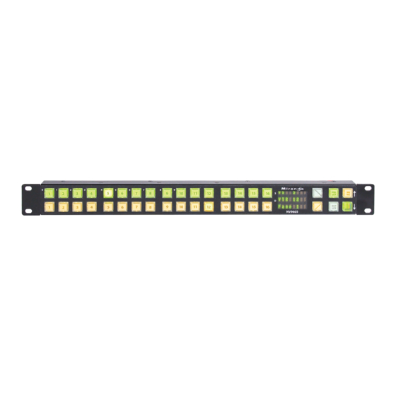
Panel Organization Function Buttons The NV9605 has an array of 32 function buttons on the left. Four of the 6 buttons on the right are function buttons. (The other 2 buttons on the right are scroll buttons.) The buttons’ functions are only slightly different in each of the 2 operating modes. (See Modes Operation, next.) -
Page 13: Alphanumeric Display
NV9605 User’s Guide The 4 function buttons on the right behave differently when you scroll: • Source buttons remain source buttons on all pages, although they can represent different sources on different pages. Destination buttons are destination buttons on all pages, although they can represent different destinations on different pages. -
Page 14: Modes Of Operation
In this mode, you can preset the NV9605’s panel ID and perform a few diagnostic tasks. • Menu mode — pressing a menu button places the NV9605 in “menu” mode. In menu mode, the buttons lose their normal functions and become part of a menu that changes as needed during menu operation. -
Page 15: Other Nv9605 Functions
NV9605 User’s Guide Other NV9605 Functions The NV9605 can be configured to perform the following additional functions: • Previous source and free source. • System salvos. • Lock/protect/release for destinations. • Multiple-level breakaways. • Broadcast data routing. - Page 16 Introduction Other NV9605 Functions...
-
Page 17: Installation
Testing ................11 Package Contents If you have ordered one or more NV9605 control panels from Grass Valley, inspect the shipping container for damage. If you find any container damage, unpack and inspect the contents. -
Page 18: Installation
Valley if you need to obtain the latest version of this NV9000 configuration software. You may use the Panel IP Configuration Utility if you want to your NV9605 to have a static IP address (with respect to the system controller) or to use DHCP. The panel, as it comes from the factory, defaults to DHCP. -
Page 19: Testing
These are points to consider after you install your NV9605 control panel(s): 1 Do the buttons illuminate? When an NV9605 powers up, one or more of its buttons are supposed to turn green or amber. Did it pass the panel test mentioned above? 2 When the NV9605 powers up and it is connected to the system controller, it should initialize completely. - Page 20 Installation Testing If (in setup mode) you do not see your designated panel ID in the ‘Preset’ display field, you have either not initialized the panel or no configuration has been created for your panel in NV9000-SE Utilities. 3 Is the system controller actually running? With the typical noise levels in a facility, it can sometimes be difficult to tell.
-
Page 21: Configuration
NV9605 Panel Configuration Page ........ - Page 22 Click ‘Add Control Panel’ at the bottom of the configuration page. The ‘Add Control Panel’ page appears: Choose “NV9605” from the ‘Type’ field. In the ID field, enter the panel ID you assigned to the panel while it was in setup mode. (You can change the panel ID in NV9000-SE Utilities.) Give a name to the panel in the name field and select a user.
- Page 23 There are 2 other buttons, ‘Suffix’ and ‘Navigate’ , both dim (disabled). These do not apply to the NV9605. Return to the ‘Control Panels’ page to view your new entry. To edit an NV9605 configuration, double-click its list entry: You will then see the panel configuration page for the selected NV9605.
-
Page 24: Nv9605 Panel Configuration Page
Configuration NV9605 Panel Configuration Page NV9605 Panel Configuration Page This is the default NV9605 panel configuration page in NV9000-SE Utilities: Panel Image: Button Definition Section Panel Options GPIO Definitions Fig. 4-1: NV9605 Configuration Page (Default) After you configure buttons the appearance of the panel buttons will have changed. The panel buttons on this page will show legends, determined from the button type assigned to the button. -
Page 25: Configuration Tasks
Configuration Tasks The person configuring an NV9605 panel will want to consider how best to use the buttons to support the devices and routers in the router control system at hand. Trade-offs must be made. -
Page 26: Panel Options
Configuration Panel Options Panel Options The panel options section, at the right of the configuration page, has two parts: drop-down menus and checkbox options. These are the drop-down menus: These are its drop-down menu options: Panel Behavioral Limited X-Y In limited X-Y mode, takes occur from a single source to a Model single destination (which is selectable). -
Page 27: Checkbox Options
NV9605 User’s Guide Default Name System Name A list of “name sets” appears in the drop-down menu. The name sets can be defined under the System Management pane of NV9000-SE Utilities. Choose ‘System Name’ in this list if you do not want, or do not care about, alternate device names. -
Page 28: Button Definitions
Button Specification The button definition section configures the button you have selected in the image of the NV9605: When you choose a button type, additional drop-down menus can appear, depending on the button type, allowing you to further specify the button’s behavior. Available options and selections vary from button type to button type. -
Page 29: Button Types
NV9605 User’s Guide Button Types These are the button types available for NV9605 configurations: Type Code Description Broadcast M, X On the data (machine control) level, the button enables a broadcast take to an additional controlled device, after a broadcast route has been initiated with a “source is master”... - Page 30 — even the user who issued the lock — from routing to the destination. The button definition has no fields to configure. The NV9605 provides no explicit indication, during operation, whether a destination is locked or unlocked. This button is available, but does not operate, in multi-destination mode.
- Page 31 Menu M, X This button puts the NV9605 panel in menu mode and displays a menu on the buttons that provides access to a variety of panel functions. Without the button, the operator has no access to the menu functions.
- Page 32 Configuration Button Types Type Code Description Previous M, X The button presets the previously routed source to the currently Source selected destination. The operator must next press ‘Take’ to restore the previous route. This function is useful when an operator makes a route in error.
-
Page 33: Multi-Destination Configuration
— to the destination assigned to the source button. (A source shift button switches between the two sources of the source buttons.) Potentially, all 36 buttons of a NV9605 could be source buttons, each having a unique destination. Thus, at that extreme, a panel in multi-destination mode could represent 36 destinations in each of the its 4 pages (a total of 144 destinations) and give operators the choice of two sources for each destination. -
Page 34: Single-Destination Configuration
Configuration Single-Destination Configuration some duplication. In this example, the limit is 32 different destinations, and 256 different sources. As another example, this organization provides 4 destinations with up to 16 sources available for each one, again with the 4 buttons on the right assigned to other functions: Dest A Dest B Dest C... -
Page 35: Operation
This chapter is intended specifically for the NV9605 panel operator. Summary As an NV9605 operator, you will be confronted initially with a relatively small and simple panel — 38 buttons with three 8-character displays. The panel’s buttons can have arbitrary legends (using plastic inserts under the button caps). -
Page 36: Limited X-Y Mode
Operation Modes of Operation The panel’s set of button functions varies slightly with the mode (or model). Generally, to operate the panel, you choose a destination, (possibly) choose desired breakaway levels, and choose a source. Choosing a source for a destination completes the take. -
Page 37: Secondary Modes
Usually, only configurers need be concerned with setup mode. Setup Mode page • Menu mode — pressing a menu button places the NV9605 in “menu” mode. In menu mode, the buttons lose their normal functions and become part of a menu that changes as needed during menu operation. -
Page 38: Source Shift
Operation Source Shift Source Shift Source shift also applies in either mode. Each source button can represent two sources. A ‘Source Shift’ button selects which of the two sources the source button will select. (The concept is similar to the shift key or the ‘caps lock’... -
Page 39: Gang Switching
2 Select any destination. Buttons The NV9605 has 3 classes of button functions: • Dedicated functions, such as ‘Default State’ and ‘Chop’ . • Variable functions, such as ‘Salvo’ , ‘Source’ , or ‘Destination’ . A salvo button executes a specific system salvo. -
Page 40: Broadcast
When you lock a destination, the ‘Destination Lock’ button goes high-tally amber. If you have a ‘Destination Protect’ button, it will also go high-tally amber. Locks can apply to selected levels in limited X-Y mode. The NV9605 provides no explicit indication, during operation, whether a destination is locked or unlocked. -
Page 41: Destination Protect
Protects can apply to selected levels in limited X-Y mode. The NV9605 provides no explicit indication, during operation, whether a destination is locked or unlocked. Free Source X, M The button selects a pre-defined phantom device that can be used to release or “free”... -
Page 42: Menu
Operation Buttons You will select one or more levels for a breakaway and then press a source button to complete the take. When all level buttons are deselected, or when all level buttons are selected, a take is “all-level. ” When one or more level buttons are selected, a take occurs on just those levels. -
Page 43: Source
NV9605 User’s Guide Source L, X, M The button selects a source. The source name appears in the ‘Status’ display. Pressing a source button completes a take. The nature of source buttons differs according to the panel’s configured operating mode: •... -
Page 44: Undefined
To remove a lock or protect. Some control panels can lock or protect both sources and destinations. However, The NV9605 provides locks and protects for destinations only. A forced release is when the lock or protect is removed by someone other than the owner. A forced release can be performed: •... -
Page 45: Takes
NV9605 User’s Guide levels become unlocked and those that were unlocked become unlocked. The same is true for protect buttons. Takes Pressing a source button completes a take, in either mode. Following are brief instructions on how to perform a take. -
Page 46: Name Sets
There are no destination buttons. Potentially, all 36 configurable buttons of a NV9605 could be source buttons, each having a unique destination. Thus, at that extreme, a panel in multi-destination mode could represent 36 destinations for each of the 4 pages or 144 destinations in total. -
Page 47: Broadcast Routes
NV9605 User’s Guide Note that when the panel is displaying alternate names, and a device does not have an alternate name, the panel displays the system name. Broadcast Routes It is easy to route a source to multiple destinations for audio and video routers. You place the panel in hold mode with the hold button. -
Page 48: Performing A Broadcast Take - Multi-Destination Mode
Operation Data Routing Performing a Broadcast Take — Multi-Destination Mode Follow these steps: 1 Press a source. That source becomes the master because the router is in data forward mode. This destination (configured on the source button) is the slave and communicates bidirectionally with the master on the machine control level. -
Page 49: Semi-Automatic Data Routing
NV9605 User’s Guide Semi-Automatic Data Routing A take involving a source or a destination having a machine control level might not occur immediately if the source or destination device is in use. This option applies in all operating modes. If neither device is “in use” the take occurs immediately. Otherwise, you need to press the source button again to complete the take. -
Page 50: Case 2 - Multi-Destination Mode
To terminate the chop, (1) press the chop button again to turn it off, then (3) select any source. Menu Mode The NV9605 enters menu mode if it has a menu button and you press the menu button. The menu uses some of the buttons on your panel. The legends and functions of these buttons in normal operating mode do not apply while the panel is in menu mode. -
Page 51: Panel Name
NV9605 User’s Guide After you enter a panel ID, press the menu button again. A confirmation message appears: 0 C a n c e l S a v e Press the left-most button to cancel the operation or press the button to its right to save your new panel ID. -
Page 52: Button Illumination
At this last step, the panel leaves menu mode and returns to normal mode. Setup Mode Setup mode occurs when the NV9605 is disconnected from its network and is freshly powered up. In setup mode, you can set or change the panel ID, identify the software version, and perform a test of the panel’s buttons. - Page 53 NV9605 User’s Guide Press the setup button to proceed to the first part of setup which is to set the panel ID: P a n e l I D The panel now allows you to enter the panel ID using buttons at the left that function as a numeric keypad.
- Page 54 Pressing the setup button will terminate the button test and return you to the initial display of setup mode. At this point — if you have a assigned your NV9605 a suitable panel ID — you may connect your NV9605 to the panel network of your NV9000 system.
-
Page 55: Gpio
Tally devices you connect to inputs can trigger events — through the NV9605 — in the router control system. The router control system can trigger events that — through the relays in the NV9605 — switch your tally devices. -
Page 56: Output
When a condition (defined for the relay) occurs, the router control system notifies the NV9605 which then opens or closes the relay. The relay switches the customer’s circuit on or off. (It does not power the circuit. Customers must provide their own power.) GPIO Configuration Concepts These are the I/O characteristics of the NV9605’s tally interface:... -
Page 57: Configuring Outputs
Click on a button under ‘Inputs’ to configure one of the 8 tally inputs. There are no actual GPIO buttons on the NV9605 control panel. Configuring Outputs Clicking an output button (one of 4) displays a “Relay Rule” dialog for the output:... - Page 58 The actual logic takes place in the router control system, based on the state of the NV9605 inputs and other system-wide events. The router control system sends signals to the NV9605 instructing it to open or close its relays.
-
Page 59: Configuring Inputs
Its 8 inputs can be switched on or off by your external devices. When an input transitions on or off, the NV9605 can respond with one of 4 actions, such as executing a salvo. (It is the system that actually executes the salvo.) - Page 60 GPIO Configuring Inputs...
-
Page 61: Technical Details
NV9605 Specifications ........ -
Page 62: Nv9605 Specifications
DC Output Fig. 7-1: The power output has Molex 4-pin plug. See Power Cord Retention, on page 56. NV9605 Specifications NV9605 Physical Specifications Specification Detail Dimensions Height: 1.72 in (43.7.9 mm), fits EIA 1 RU (1.75 in or 44.5 mm), Width: 19.0 in (482.6 mm). -
Page 63: Environmental Specifications
Initial Panel State Destination: the configured default. Buttons: low-tally is 40% brightness by default and stays at its most recent setting. Configuration Page The initial NV9605 configuration has no buttons defined. The default panel options are: Behavioral model: Limited X-Y. Release mode: Normal. -
Page 64: Power Cord Retention
Technical Details Power Cord Retention Power Cord Retention Use the supplied retention strap to keep the AC power cord firmly connected to the power supply. Follow these steps to use the strap: 1 Firmly insert the AC power cord into the power supply. Examine the last figure in this section to see how the strap should be applied. -
Page 65: Drawings
NV9605 User’s Guide Drawings The drawings on the following page provide overall and critical dimensions. - Page 66 Technical Details Drawings Fig. 7-2: Front, Top, and Rear Views of the NV9605...
-
Page 67: Glossary
AES router, and time code on input port 8 of the time code router. GPIO General Purpose Input and Output. A generic term for the NV9605’s tally interface. The tally interface is called the “GPI Interface” at the rear of the NV9605. - Page 68 Glossary one or more input ports. A destination is a device that is connected to one or more output ports. An example of such a device would be a monitor. A device can be both a source and destination. An example of such a device is a VTR. System The system administrator is the person responsible for installing, configuring, and administrator...
-
Page 69: Index
Index free source ......7, 22, 33 hold ......22, 31, 33 level . - Page 70 ......5, 32 Contact Grass Valley ......67 status .
- Page 71 NV9605, front, photo ..... . 3 NV9605, rear view ......58 ID, panel .
- Page 72 ......41 NV9605 ....... . .3, 9–10 Messages front view .
- Page 73 SE (abbreviation for NV9000-SE Utilities) NV9605, rear ......4 Search, Acrobat ......2 power cord retention .
- Page 74 Index Software ........10 Software version ......42 Software version (submenu) .
-
Page 75: Contact Us
1-800-547-8949 (US and Canada) or +1 530 478 4148. To obtain a local phone number for the support center nearest you, please consult the Contact Us section of Grass Valley’s website ( www.grassvalley.com An online form for e-mail contact is also available from the website.
Need help?
Do you have a question about the NV9605 and is the answer not in the manual?
Questions and answers