Table of Contents
Advertisement
Quick Links
Advertisement
Table of Contents

Subscribe to Our Youtube Channel
Related Manuals for GRASS VALLEY NV9641A


Summary of Contents for GRASS VALLEY NV9641A
- Page 1 NV9641A NV9000 Control Panel User’s Guide UG0079-00 20 Nov 2014...
- Page 2 Please read the following terms and conditions carefully. By using NV9641A documentation, you agree to the following terms and conditions. Grass Valley hereby grants permission and license to owners of NV9641A routers to use their product manuals for their own internal business use. Manuals for Grass Valley products may...
- Page 3 Declarations of Conformance on file in the Grass Valley offices in Grass Valley, California USA. Software License Agreement and Warranty Information Contact Grass Valley for details on the software license agreement and product warranty.
- Page 4 Grass Valley has a substantial program in place for RoHS compliance that includes significant investment in our manufacturing process, and a migration of Grass Valley product electronic components and structural materials to RoHS compliance.
- Page 5 The fuse symbol indicates that the fuse referenced in the text must be replaced with one having the ratings indicated. The presence of this symbol in or on Grass Valley equipment means that it has been designed, tested and certified as complying with applicable Underwriter’s Laboratory (USA) regulations and recommendations.
- Page 6 • To avoid fire hazard, use only the specified fuse(s) with the correct type number, voltage and current ratings as referenced in the appropriate locations in the service instruc- tions or on the equipment. Always refer fuse replacements to qualified service person- nel.
-
Page 7: Table Of Contents
NV9641A Panel Configuration Page........ - Page 8 Table of Contents Button Page Table ................36 XY/MD Model .
- Page 9 The GPIO Section of the NV9641A Page ........
- Page 10 NV9641A Specifications ........
-
Page 11: Preface
............2 Chapter Structure The following chapters provide detailed information regarding the NV9641A control panel: •... -
Page 12: Terms, Conventions And Abbreviations
Press the SRC 12 button ... The following terms and abbreviations are used throughout this guide: • The term “control panel” refers to the NV9641A control panel and to NV96xx control panels, in general. • “High tally” means that a button is brightly illuminated. -
Page 13: Introduction
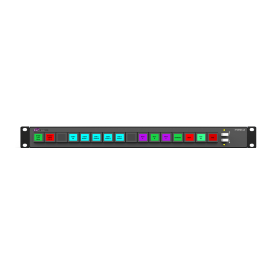
..............7 Summary The NV9641A is a 1RU control panel featuring 16 LCD function buttons (illuminated in various colors and having 1 to 3 lines of text) and 2 up/down (scroll) buttons. -
Page 14: Behavioral Models
Panel Organization Function Buttons The NV9641A has an array of 16 LCD buttons. Each has 3 lines of text (up to 8 characters per line). The buttons can display one of seven colors dynamically: nominally red, green, blue, purple, amber, yellow, or grey. We say a button is “dark” when its LCD is turned off. -
Page 15: Up/Down Buttons
During configuration, you can prescribe NV9641A behavior that depends on the tally inputs. What you connect to the tally interface is, of course, up to you. Grass Valley provides a breakout cable (WC0053) for the tally connector as a purchase option. -
Page 16: Modes Of Operation
Single-destination” mode is not a distinct mode, but we mention it because it is a mode on some other panels and can be simulated on the NV9641A. It can be combined with the other two modes. You can create many different forms of “single-destination” mode. This mode may in fact have more than a single destination. -
Page 17: Other Nv9641A Functions
NV9641A User’s Guide Other NV9641A Functions The NV9641A can be configured to perform the following additional functions: • Previous source, free source, and “quick” source. • Lock/protect/release for destinations. • Return to a pre-defined (or default) state. • Hold breakaway levels. - Page 18 Introduction Other NV9641A Functions...
-
Page 19: Installation
................. . . 12 Package Contents If you have ordered one or more NV9641A control panels from Grass Valley, inspect the shipping container for damage. If you find any container damage, unpack and inspect the contents. If the contents are damaged, notify the carrier immediately. -
Page 20: Installation
NV9000 configuration software. You may use the Panel IP Configuration Utility if you want your NV9641A to have a static IP address or to change it back to DHCP. The panel, as it comes from the factory, defaults to DHCP. -
Page 21: Initialization
Follow these steps for each NV9641A you are installing: 1 Power up the NV9641A. Do not connect its Ethernet cable (or disconnect it if it is connected). After a few seconds, the alphanumeric display will show ‘Acquire IP Address’ and show the panel’s current panel ID. -
Page 22: Testing
Does it pass the panel test mentioned above? 2 When the NV9641A powers up and it is connected to the system controller, it should initial- ize completely. (That takes about 30 seconds.) Whatever configuration exists for that panel should be loaded and the buttons appropriate for that configuration should light in the col- ors appropriate for that configuration. -
Page 23: Configuration
The software with which to configure the NV9641A is NV9000-SE Utilities. Figure 4-1, following, shows the default NV9641A panel configuration page from NV9000-SE Utilities. The Panel IP Configuration Utility is also available if you want the NV9641A to take a static IP address. -
Page 24: Adding A Panel To An Nv9000 Configuration
Adding a Panel to an NV9000 Configuration Adding a Panel to an NV9000 Configuration You must create configurations for the NV9641A using NV9000-SE Utilities. We assume that you are familiar enough with NV9000-SE Utilities that you can understand the following material. It is not difficult material, but some of the concepts might not be familiar to everyone. - Page 25 Global Navigation on page 43. Return to the ‘Control Panels’ page to view your new entry. To edit an NV9641A configuration, either double-click its list entry or select the entry and then click ‘Edit Panel Configuration’: You will then see the panel configuration page for the selected NV9641A.
-
Page 26: Nv9641A Panel Configuration Page
Page Table GPIO Defi- nitions Fig. 4-1: NV9641A Configuration Page (Default) Similar pages exist for NV9641A suffix templates and for global navigation templates. See Global Navigation on page 43. The items on the page shown in Figure 4-1 apply under the “XY/MD” behavioral model. A some- what different page appears when you choose the “paging”... -
Page 27: Regions Of The Configuration Page
Above the ‘Revert to Saved’ and ‘Save’ buttons (always present) there are 5 main regions: • A graphic representation of the NV9641A panel. On the left are 16 LCD function buttons. Click on a button to assign a function to it. In some cases, you can click or double-click certain buttons to execute the button function. -
Page 28: Configuration Tasks
Commitment Buttons Configuration Tasks The person configuring an NV9641A panel will want to consider how best to use the button page tree under the XY/MD model or the list structure of the button page list under the paging model to support the devices and routers in the router control system at hand. The task is non- trivial. -
Page 29: Panel Options
NV9641A User’s Guide Panel Options The first panel option selects the behavioral model of the panel: XY/MD or paging. The panel options differ between the two models. The default model is XY/MD mode. Changing from one behavioral model to the other will erase the panel configuration. A confir-... - Page 30 Configuration Panel Options Default None After a reset, the panel displays no destination device. (This is not Destination recommended.) ‹device› The Panel uses the specified device as the destination after a reset. (The ‘Default State’ button also returns the panel to this destina- tion.) Preset Monitor None...
-
Page 31: Checkbox Options
NV9641A User’s Guide MD Data Automatic If a machine control (i.e., data) level is involved in a route, the sys- Routing Mode tem makes the route on the control level even if the control port is in use on the source or destination device. It breaks the previous control connection and then makes a new control connection for the route in progress. - Page 32 After selecting many MD destinations (with ‘Hold’ mode on), it can be time-consuming and error-prone to find them all (and no others) to deselect them after a take. When you enable this option, the NV9641A does exactly that (and turns off hold mode). •...
-
Page 33: Options Under The Paging Model
A ‘Source/Destination’ button selects a source and a destination. When this box is checked (as it is in the default NV9641A configuration) the button performs an immediate take. When the checkbox is clear, the button sets up the take and the operator must press a ‘Take’ but- ton to complete the take. -
Page 34: Drop-Down Menus
Configuration Panel Options Drop-Down Menus These are the drop-down menu options under the paging model: Panel Behavior XY/MD Mode The panel configuration uses the XY/MD model. Model XY/MD supports a tree of button pages and allows the operator the choice of X-Y mode (multiple levels, single destination) or MD mode (all levels, multiple destinations) at any time. -
Page 35: Button Definitions
The set of devices in a cate- gory can change over time (as the configuration database changes); the NV9641A device list changes also. The number and names of categories can also change over time and the NV9641A will track those changes too. -
Page 36: Button Specification
Configuration Button Definitions When a device list appears on the panel, the system lights the ‘up’ button so the operator can easily return to the page containing the category button. Note Certain button fields contain a colon (:) and number after the data in the field. The number is the record ID of the object in the NV9000 configuration database. -
Page 37: Button Types
NV9641A User’s Guide Check box “Place this button on all child pages. ” When the operator presses a ‘Navi- gate’ button, its target page appears on the buttons. Any page can have multiple navigate buttons and therefore multiple target pages. If you check this option, the button you are defining will occur, in the same position, on all pages in the subtree under the navigation button. - Page 38 Configuration Button Definitions Type Paging Description Category Displays a category’s device list. When you assign a category button, two additional drop-down menus appear: ‘Src Category’ and ‘Dst Category’ . Choose a category from one of the category lists. When you choose a source category, the destina- tion categories become inaccessible and vice versa: a category button must be either a source category or a destination category.
- Page 39 Menu This button puts the NV9641A panel in menu mode and displays a menu on the LCD buttons that provides access to a variety of panel options. The button is required if you want the user to have access to the menu.
- Page 40 Configuration Button Definitions Type Paging Description Name Set The button toggles the panel between its default name set and the Toggle “system name” set. One or the other becomes the active name set. The button definition has no fields to configure. If the default name set is the system name set, the button would be a no-op.
- Page 41 NV9641A User’s Guide Type Paging Description Save When this function is enabled (its button is high tally), whatever is on Preset preset is retained (on preset) after a take. When the function is disabled (its button is low tally), preset is cleared after a take.
- Page 42 Configuration Button Definitions Type Paging Description Source Means “source is the master” and makes the source device the master. Master Otherwise, the destination is the master. The button is a toggle: Press it once to make the source the master (it goes high-tally);...
- Page 43 NV9641A User’s Guide Type Paging Description The ‘X-Y Display’ button displays current route status — in X-Y mode or Display multi-destination mode. Pressing this button has no effect. It also displays other messages in other circumstances, as required. Prior to a take, the ‘X-Y Display’ button displays the preset destination name (and turns low-tally red if that destination is locked or protected by another user.)
-
Page 44: Edit Navigation Button' Dialog
This option creates a new page in the button tree. During operation, the navigation button you are creating will cause the NV9641A to display, or jump to, that page. The name of the page and the button caption are what you type in the three lines for the button caption. You can change the name of the page in the button page list. -
Page 45: Auto-Fill Options
This options does not create a new page in the button tree. The navigation button you are creating will cause the NV9641A to display the page you select in the associated drop down menu. The button caption is what you type in the three lines for the button caption. -
Page 46: Button Page Table
Configuration Button Page Table • Destination Devices Auto-fill using destination devices is the same as for source devices, except that destination devices are chosen. • Source/Dest Devices This option creates subpages of ‘Source/Destination’ buttons. All use the same destination, which you specify in the ‘Destination Device’ field that becomes enabled for this option. The sources can vary according to the sub-option: •... -
Page 47: Xy/Md Model
NV9641A User’s Guide XY/MD Model This page table lists the pages of the button page tree. It has 3 columns: ‘Page Number’ , ‘Page Name’ , and ‘Link to Page Num(s)’ . The button page at the top (or root) of the tree is called “Default. ” Initially, the tree has just the default page, until you add other pages. -
Page 48: Paging Model
Configuration Button Page Table When you double-click the page number field of a page you want to edit, the image of that page appears in the panel graphic area. The ‘Links to Page Num(s)’ column lists, for any page, the other pages that refer to it. Using the links column you can mentally examine the tree structure or create a sketch of the tree struc- ture. -
Page 49: Tally (Gpio) Window
It has two sections: inputs and outputs. By clicking on one of the input or output buttons, you can configure the input or output. (The NV9641A has no actual tally buttons. It does have a DB25 connector at the rear. The buttons are present in the configuration page to allow you to configure the tally interface.) If you are interested in configuring the tally interface, read Chapter 6, GPIO, on page 73. -
Page 50: Behavior
Configuration Selection Buttons Behavior XY Mode When the panel is in X-Y mode, a set of selection buttons presents a set of virtual levels. The levels displayed correspond to the levels in the level set of a selected destination device. If a selection button is dark and blank, the level does not exist in the level set. -
Page 51: Md Mode - Hold Mode
NV9641A User’s Guide MD Mode — Hold Mode In hold mode, selection buttons are not mutually exclusive. To perform MD takes, the operator selects one or more MD devices. All of them turn on (high-tally). The operator then selects a source (which becomes preset for all the selected devices). -
Page 52: Single-Destination Mode
4 Press the down button if, after configuring each selection button, you have additional MD destinations to commit to selection buttons. The next set of selection buttons appears on the NV9641A image. 5 Repeat steps 3 and 4 until you have committed all the MD destinations that you want. -
Page 53: Global Navigation
2 In the ‘Add Control Panel’ page, complete the details as you would for a panel: The panel type is NV9641A. Specify a panel ID, a name, and choose ‘New’ in the options section. 3 Rather than click the ‘Next’ or ‘Finish’ button, click the ‘Suffix’ or ‘Navigate’ button. Doing so creates a global navigation page of the appropriate type. -
Page 54: Referencing A Suffix Template
Configuration Global Navigation Referencing a Suffix Template Suffix pages can be accessed through ‘Category’ buttons. When you create a ‘Category’ button, the button type region displays a checkbox option: ‘Use global suffix page to select devices’: Suffix Suffix checkbox template selection When you check the option, an addition ‘Suffix Page’... -
Page 55: Composing Suffix Templates
NV9641A User’s Guide When you create a ‘Global Navigate’ button, the button definition has a ‘Navigation Btn’ field: Choose a navigate template in that field. The global navigation page and any of its subpages appears in the panel configuration’s button page list: Global navigation page(s) ... -
Page 56: Template Changes
‘Push changes to panel configs’ . When you do, the configuration software adjusts all NV9641A panel configurations to use the modified suffix template. This might over- ride changes you have made to the copy of the suffix page in some panel configuration. -
Page 57: Template Changes
NV9641A User’s Guide Template Changes If you make a change to a navigate template and it is in use by one or more panel configura- tions, you will want to click ‘Push changes to panel configs’ . You can see the panel configurations in the list under ‘Panel References’:... - Page 58 Configuration Global Navigation...
-
Page 59: Operation
This chapter is intended specifically for the NV9641A panel operator. Summary As an NV9641A operator, you will be confronted initially with a small panel — 16 buttons of various colors with brief legends and certain color codes. Your NV9641A will be configured according to one of two behavioral models: •... -
Page 60: Modes Of Operation
• Setup mode — where the NV9641A is freshly powered up, but disconnected from the network. In this mode, the configurer can preset the NV9641A’s panel ID and perform a few diagnostic tasks. Usually, only configurers need be concerned with setup mode. -
Page 61: Button Legends
Salvo mode — pressing a salvo button and then a take button executes a salvo. The duration of a salvo is indeterminate. • Menu mode — pressing a menu button places the NV9641A in “menu” mode. In menu mode, the LCD button array becomes a menu button panel that changes as needed during menu operation. -
Page 62: Level Mapping
Operation Summary When a source is preset, prior to a take, the level buttons show the preset source on the middle line of text and the buttons turn yellow: Source CAM4 preset prior to a take. XY-STAT XY-STAT CAM3 CAM3 CAM3 CAM3 ––––––––... -
Page 63: Lists
NV9641A User’s Guide Lists The NV9641A can display devices, categories, and salvos in automatically generated lists under the XY/MD model. There are three kinds of lists: • Generated during configuration of a navigation button. These lists are characterized by the presence of “Back”... -
Page 64: Level Grouping
The levels ‘Video’ and ‘Audio’ are abstract levels; the other levels are basic levels. The NV9641A, at present, ignores the concept of level groups, and presents any configured level groups as completely expanded. That is, it always displays basic levels and never abstract levels. -
Page 65: Buttons
4 When you have the desired source selected, press a ‘Back’ button to return to the previous page. Buttons The NV9641A has four classes of button functions: • Dedicated functions, such as ‘Default State’ or ‘Chop’ . •... -
Page 66: Back
You can scroll the pages using back and forward buttons. If you press ‘Back’ while on the first page of the list, the NV9641A returns to the page containing the category button. -
Page 67: Chop
You can scroll the pages using the up and down buttons. If you press ‘Up’ while on the first page of the list, the NV9641A returns to the button page containing the category. The button text is the category name. Category names tend to be short. -
Page 68: Destination Lock
Operation Operating Concepts you navigate the list by pressing “back” and “forward” buttons or (2) as a result of pressing a destination category button, in which case you navigate by pressing the up and down buttons. The button text is normally the destination device’s mnemonic, but the configurer can assign the button any text on pages that are not automatically generated. -
Page 69: Free Source
NV9641A User’s Guide MD Mode In MD mode, when you select a protected MD destination with a button, the ‘Destination Protect’ button goes high-tally. To protect or unprotect MD destinations, select the destinations and press a ‘Destination Protect’ button. X-Y Mode In X-Y mode, you may protect or unprotect the current destination on each of its levels. -
Page 70: Level Map
The default button text is “Level Map” but the button can have any legend. P Menu The button puts the NV9641A panel in menu mode and displays a menu, on the LCD buttons, that provides access to a variety of panel options. -
Page 71: Global Navigate
‘Preset Release’ button and tell you who locked or protected the source. You can release it if your panel has “forced release” enabled. (Note that you cannot lock or protect sources with the NV9641A.) Press the ‘Preset Release’ button to release the source. -
Page 72: Salvo
Operation Operating Concepts P Salvo This button executes a system salvo. A salvo is a pre-defined set of NV9000 commands. The button text is the salvo’s mnemonic. When you press the salvo button, the panel tempo- rarily enters “salvo” mode. To confirm that you want to execute the salvo, press a ‘Take’ button. (You might have to navigate to a ‘Take’... -
Page 73: Source
NV9641A User’s Guide 4 Press ‘Take’ . The selected MD devices remain selected. If you have not enabled ‘Hold’ mode, 1 Select an MD devices. Scroll the MD device list as needed. 2 Select a source. 3 Repeat steps 1 and 2 until your presets are complete. -
Page 74: Take
Operation Operating Concepts Pressing the ‘Source is Master’ button turns off the ‘Broadcast’ button and vice versa. The default button text is “Src Mstr” but the button can have any legend. P Take In X-Y mode, a take button switches the preset source device to the selected destination device on selected levels. -
Page 75: Lock, Protect, And Release
Release To remove a lock or protect. Some control panels can lock or protect both sources and destinations. However, The NV9641A provides locks and protects for destinations only. A forced release is when the lock or protect is removed by someone other than the owner. A forced release can be performed: •... -
Page 76: Name Sets
Operation Operating Concepts 4 Repeat steps 2 and 3 for all destinations you intend to use. 5 Press ‘Take’ . When ‘Hold’ is enabled in MD mode, you can select many MD destinations at once. Subse- quently selecting a source assigns the source to all selected MD destinations. You can turn ‘Hold’ on and off as you require during an MD take. -
Page 77: Removing Broadcast Routes
NV9641A User’s Guide 1 Ensure that the panel is in “source is master” mode. It is either in “source is master” mode by default or you must press the ‘Source is Master’ button to activate the mode. It is active when the ‘Source is Master’... -
Page 78: Semi-Automatic Data Routing
(3) select any source. Menu Mode The NV9641A enters menu mode when it has a menu button and you press it. The menu has 4 menu choices and an exit button: SOFTWARE SOFTWARE •... -
Page 79: Software Versions
OOOOOO O4 O4 The 3 buttons on the left tell you the current versions of the software in the NV9641A. Generally, this is of no relevance unless you are in a diagnostic situation. Press ‘Exit’ on the right to return to the menu. -
Page 80: Setup Mode
85 for a color chart. Setup Mode Setup mode occurs when the NV9641A is disconnected from its network and is freshly powered up. In setup mode, you can set or change the panel ID, determine software versions, and perform a test of the panel’s buttons. It is in setup mode that you must initially set the panel ID. - Page 81 NV9641A User’s Guide In the setup menu, press the ‘Software Versions’ button. Three buttons appear: CPLD 1 CPLD 1 • • • SVO546- SVO546- VERSION VERSION EXIT EXIT O4 BO O4 BO O1 O1 The 2 buttons on the left give the software version numbers. Use the ‘Exit’ button on the right to return to the setup menu.
- Page 82 Operation Setup Mode...
-
Page 83: Gpio
The tally interface includes 8 optically isolated inputs and 4 solid-state relay outputs (also opti- cally isolated). Tally devices you connect to inputs can trigger events — through the NV9641A — in the router control system. The router control system can trigger events that — through the relays in the NV9641A —... -
Page 84: Output
GPIO GPIO Configuration Concepts When the input transitions off or transitions on, the NV9641A notifies the router control system, which carries out the task defined for the input (if a task has been configured). During contact closure, a current of 1.2mA flows. A maximum of 48VDC can be applied to the tally input for less than 5 seconds without failure. -
Page 85: The Gpio Section Of The Nv9641A Page
User’s Guide The GPIO Section of the NV9641A Page SE’s NV9641A configuration page provides a GPIO section, below the tree window: Click on a button under ‘Outputs’ to configure one of the 4 tally outputs. Click on a button under ‘Inputs’ to configure one of the 8 tally inputs. - Page 86 The actual logic takes place in the router control system, based on the state of the NV9641A inputs and other system-wide events. The router control system sends signals to the NV9641A instructing it to open or close its relays.
-
Page 87: Configuring Inputs
An event is signalled when a transition occurs on the input from on to off or from off to on. You can configure the NV9641A to recognize either occurrence on any of the 8 inputs, and specify one of 4 behaviors for each event or both: 1 Execute a salvo. - Page 88 Its 8 inputs can be switched on or off by your external devices. When an input transitions on or off, the NV9641A can respond with one of 4 actions, such as executing a salvo. (It is the system that actually executes the salvo.)
-
Page 89: Technical Details
Technical Details Chapter 7 provides electrical and mechanical specifications for the NV9641A. Topics Power Specifications ..............79 NV9641A Specifications . -
Page 90: Nv9641A Specifications
DC Output Fig. 7-1: The power output has Molex 4-pin plug. See Power Cord Retention on page 86. NV9641A Specifications NV9641A Physical Specifications Specification Detail Dimensions Height: 1.72 in (43.7 mm), fits EIA 1 RU (1.75 in or 44.5 mm), Width: 19.0 in (482.6 mm). -
Page 91: Environmental Specifications
Buttons: high-tally is maximum brightness; low-tally is low brightness. Configuration Page The initial configuration page for a new NV9641A configuration provides 8 selection buttons (recommended), an XY/MD mode selection button, an X-Y Display button, and a take button. The default panel options are: Panel mode: Multi-destination. - Page 92 Technical Details Drawings Fig. 7-2: Front and Top Views of the NV9641A...
- Page 93 NV9641A User’s Guide Fig. 7-3: Rear and Top Views of the NV9641A...
- Page 94 Technical Details Drawings...
-
Page 95: Misc. Topics
Misc. Topics Chapter 8 provides the following. Topics LCD Buttons ................85 Scroll Button Legends . -
Page 96: Power Cord Retention
Misc. Topics Power Cord Retention To apply a label to a button, pull the clear plastic cap from the button, insert the label in the cap, and replace the cap. The caps come off easily. No tools are required. We recommend that you not use adhesive. -
Page 97: Ordering Information
If necessary, adjust and cinch it more tightly. Ordering Information These are the NV9641A components: PS0001 12V power supply, 4-pin Molex connector, with cord, and cord retention strap. - Page 98 Misc. Topics Ordering Information...
-
Page 99: Glossary
8 of the time code router. GPIO General Purpose Input and Output. A generic term for the NV9641A’s tally interface. The tally interface is called the “GPI Interface” at the rear of the NV9641A. - Page 100 Glossary A device can be both a source and destination. An example of such a device is a VTR. System The system administrator is the person responsible for installing, configuring, and maintaining a administrator router control system. Tally (1) High or low button illumination. (2) Tally interface to be defined.
-
Page 101: Index
Index Broadcast routes ........66 Button add control panel . - Page 102 NV9641A ........13...
-
Page 103: Electrical Specifications
Global navigation ........43 NV9641A, rear view ......83 Global navigation templates . - Page 104 Levels .........4, 53–54 install the NV9641A ......10 License .
- Page 105 (page) ......14 NV9641A ......2–3, 9–10, 13, 87 Panel ID .
- Page 106 Rules, relay ......... . .75 NV9641A, rear ........3 power cord retention .
-
Page 107: Specifications
Tree, button ......... . 4 environmental, NV9641A ......81 Tree-structured button layout . - Page 108 Index...
-
Page 109: Contact Us
Contact Us Grass Valley Technical Support For technical assistance, please contact the Grass Valley Technical Support center nearest you: Americas Asia Office hours: 9:00 a.m. – 9:00 p.m. (EST) Office hours: 9:30 a.m. – 6:00 p.m. (GMT+8) Telephone: +1-800-547-8949 Telephone:...
Need help?
Do you have a question about the NV9641A and is the answer not in the manual?
Questions and answers