Table of Contents
Advertisement
Advertisement
Table of Contents

Related Manuals for Planmeca Viso


Summary of Contents for Planmeca Viso
- Page 1 Planmeca Viso ™ technical manual 30005968...
-
Page 3: Table Of Contents
Cleaning..........................48 4.1.2 Labels..........................48 4.1.3 Unit safety.......................... 48 Electrical safety measurements......................49 Mechanical checks......................... 51 4.3.1 Column motor nut.......................51 4.3.2 Lubrication..........................53 Software update..........................53 X-ray measurements and exposure values..................53 4.5.1 Non-invasive testing......................54 4.5.2 Direct-from-unit-signals testing...................54 Technical manual Planmeca Viso... - Page 4 Removing patient support covers..................130 6.1.4 Removing column covers....................131 Replacing PCBs........................... 137 6.2.1 Replacing moving column PCBs..................138 6.2.2 Replacing input PCB......................140 6.2.3 Replacing C-arm PCBs....................142 Replacing position sensors......................143 Replacing battery on CPU3 PCB....................146 Planmeca Viso Technical manual...
- Page 5 Table of contents Technical manual Planmeca Viso...
- Page 6 IEC 60364 - equipment is used according to the operating instructions. Planmeca pursues a policy of continual product development. Although every effort is made to produce up-to-date product documentation this publication should not be regarded as an infallible guide to current specifications. We reserve the right to make changes without prior notice.
-
Page 7: General And Technical Data
(CBCT) to produce three-dimensional (3D) X-ray images. Panoramic, cephalometric and projection radiography techniques can be used for two- dimensional (2D) X-rays. This manual describes how to maintain and service the Planmeca Viso X-ray unit. These instructions include options that may not be available in all countries. -
Page 8: Warnings And Cautions
The fuse or main switch must be lockable into off-position. Turning off the unit from its own mains switch DOES NOT cut off the mains voltage from all internal nodes. Wait for 2 minutes before touching any electrical parts. Planmeca Viso Technical manual... -
Page 9: Symbols On Product Labels
CAUTION GENERAL SAFETY RULES The unit must be serviced only by qualified personnel, trained by PLANMECA. Repairs and parts replaced by unqualified personnel carry no warranty. Periodical maintenance as described in this manual must be performed on a regular basis, to ensure the safety and image quality of the unit. - Page 10 To avoid risk of electric shock, this equipment must only be connected to a supply mains with protective earth. Electrostatic sensitive device (Standard IEC 60417) Warning, hot surface (Standard ISO 7010). General warning (Standard ISO 7010). Planmeca Viso Technical manual...
-
Page 11: Unit Overview
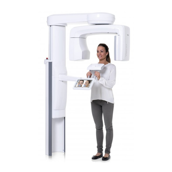
1 General and technical data 1.4 Unit overview The following picture shows the main features of the Planmeca Viso X-ray unit. 1. C-arm 2. Sensor 3. Patient support 4. Patient handles 5. Touch screen 6. Moving column 7. Stationary column 8. -
Page 12: Touch Screen
X-ray unit will carry out a self-test which takes approximately 75 seconds. The X-ray unit is then ready for use. NOTE To prolong the lifetime of the Planmeca Viso X-ray unit, always switch off the X-ray unit when it is not in active use. 1.4.2 Touch screen NOTE Do not use sharp objects to operate the touch screen. -
Page 13: Emergency Button
4. Touch the adjustment markers in the order they appear on the screen. After touching the final adjustment marker, the X-ray unit will start up normally. 1.4.3 Emergency button The emergency stop button is located on the top of the stationary column. Technical manual Planmeca Viso... - Page 14 The up / down movement will stop within a distance of 10 mm (0.4 in.). A help message will appear on the touch screen. Guide the patient away from the X-ray unit. Then release the emergency stop button. The X-ray unit will automatically restart. Planmeca Viso Technical manual...
-
Page 15: Exposure Switch
1 General and technical data 1.4.4 Exposure switch 1.4.5 Space requirements The following table lists the space requirements for the Planmeca Viso X-ray unit. Unit dimensions (without cephalostat) 1385 (W) x 1560 (D) x 2390 (H) mm 54.5 (W) x 61.42 (D) x 94.1 (H) in. - Page 16 The following sections describe the X-ray unit dimensions and minimum space requirements in more detail. 1.4.5.1 Minimum required space The following figures show the recommended practical operational space requirements for the Planmeca Viso X-ray unit. Without cephalostat: Planmeca Viso Technical manual...
- Page 17 1 General and technical data With cephalostat: Technical manual Planmeca Viso...
- Page 18 1 General and technical data X-ray unit height: NOTE The distances marked are distance added to the nominal installation and movement space requirements. NOTE The maximum height can be adjusted to suit clinics with low ceiling. Planmeca Viso Technical manual...
- Page 19 1.4.5.2 Support frame dimensions If needed, e.g. because of narrow doors or stairs, the X-ray unit can be moved in its wooden support frame. In the following, the wooden support frame dimensions for different Planmeca Viso X-ray unit models are presented. Width (1)
-
Page 20: Input Connections
1 General and technical data 1.4.6 Input connections The following image shows the different inputs available on the underside of the fixed column top. 1. Viso Ethernet port (1 Gbit/s) 2. Additional Ethernet port 3. Exposure switch ports (blocked) (10/100 Mbit/s) 4. -
Page 21: Product Labels
1 General and technical data 1.5 Product labels The following image shows the device plate for Planmeca Viso. The following image shows the X-ray tube assembly label. Technical manual Planmeca Viso... -
Page 22: Technical Specifications
Maximum apparent resistance of supply mains 0.5 Ohm 1.6.1 Technical data Classification Medical Device Directive 93/42/EEC (Class IIb) RoHS 2011/65/EU IEC 60601‐1 Class I, type B CISPR 11 Class B IP Classification IPX0 Applied parts (according to IEC 60601‐1: 2012) Planmeca Viso Technical manual... - Page 23 Pulsed, effective 1.5 ‐ 36 s as indicated ±10% Pan (SmartPan) 2.5 – 15.6 s as indicated ±10% ProCeph 0.1 – 1.6 s as indicated ±10% 3D / Pan (SmartPan) 700 mm Ceph 1700 mm (66.9 in.) Technical manual Planmeca Viso...
- Page 24 Transport: Temperature ‐20°C ‐ +60°C (‐4°F ‐ +140°F) Relative humidity 10 ‐ 90% RH (non-condensing) Air pressure 700 ‐ 1060 hPa Storage: Temperature ‐10°C ‐ +50°C (+14°F ‐ +122°F) Relative humidity 10 ‐ 90% RH (non-condensing) Planmeca Viso Technical manual...
-
Page 25: Original Manufacturer
Phone: +358 20 7795 500, Fax: +358 20 7795 555, www.planmeca.com 1.7 User's statement This section contains the user’s statement information for Planmeca Viso equipped with 120 kV tube head (Toshiba D-059SBR or Superior SXR 130-10-0.5 SC). Values differing between the tube head types are separately presented for each tube head type. - Page 26 1 General and technical data User's statement information for Planmeca Viso Feature / property Details Rated line voltage 100 V - 240 V~ ±10% Maximum line current Maximum 15 Amperes at 100 V~, 8 A at 230 V~ Technique factors that constitute the maximum...
-
Page 27: Definition Of Measurement Criteria
1 General and technical data 1.8 Definition of measurement criteria Definition of measurement criteria for Planmeca Viso Criteria Details Exposure time The beginning and end points of the exposure time are defined at 70% of the peak radiation waveform measured with a calibrated X-ray monitor. - Page 28 1 General and technical data Definition of measurement criteria for Planmeca Viso Criteria Details Dimensions of the tube head assembly (WxHxD) 235 mm x 340 mm x 120 mm Weight of the tube head assembly 13.4 kg without collimator assembly. 16.4 kg with collimator assembly.
- Page 29 2. Time (minutes) 3. Joules x 1000 (kJs) 4. Cooling 5. Heating (435 Watts) 6. Heating (291 Watts) 7. Heating (148 Watts) Single load rating of X-ray tube Toshiba D-059SBR: 1. Tube current (mA) 2. Exposure time (seconds) Technical manual Planmeca Viso...
- Page 30 Reference axis to which the target angle and the focal spot characteristics of the X-ray tube refer 90° with respect to the anode-cathode axis. Emission & filament characteristics of the X-ray tube Toshiba D-059SBR: 1. Tube current (mA) 2. Filament current (A) 3. Filament voltage (V) Planmeca Viso Technical manual...
- Page 31 X-ray tube assembly heating/cooling curve 1. kJ 2. Minutes Tube head assembly Reference axis to which the target angle and the focal spot characteristics of the tube head assembly refer / Indication of focal spot 90˚ SID, SOD and FOV Technical manual Planmeca Viso...
- Page 32 1 General and technical data Planmeca Viso Technical manual...
-
Page 33: Emc Information
Guidance and manufacturer’s declaration - electromagnetic emissions The Planmeca Viso X-ray unit is intended for use in the electromagnetic environment specified below. The customer or the user of the X-ray unit should assure that it is used in such an environment. - Page 34 Guidance and manufacturer’s declaration - electromagnetic immunity The Planmeca Viso X-ray unit is intended for use in the electromagnetic environment specified below. The customer or the user of the X-ray unit should assure that it is used in such an environment.
- Page 35 Guidance and manufacturer’s declaration - electromagnetic immunity The Planmeca Viso X-ray unit is intended for use in the electromagnetic environment specified below. The customer or the user of the X-ray unit should assure that it is used in such an environment.
- Page 36 X-ray unit should be observed to verify normal operation. If abnormal performance is observed, additional measures may be necessary, such as re-orienting or relocating the X-ray unit. Over the frequency range 150 kHz to 80 MHz, field strengths should be less than 3 V/m. Planmeca Viso Technical manual...
- Page 37 The Planmeca Viso X-ray unit is intended for use in an electromagnetic environment in which radiated RF disturbances are controlled. The customer or the user of the Planmeca Viso X-ray unit can help prevent electromagnetic interference by maintaining a minimum distance between...
-
Page 38: Settings
The password is 1701. 2.1.1 Calibrations Select Calibrations. The unit calibrations are performed in this mode. NOTE Detailed descriptions of calibrations are given in respective sections later in this manual. Planmeca Viso Technical manual... -
Page 39: Unit-Specific Settings
2.1.2 Unit-Specific Settings Select Unit-Specific Settings. 2.1.2.1 Set Parameter Limits In this mode the maximum and minimum values of the kV and the minimum mA range can be set for panoramic, cephalometric and 3D exposures. Technical manual Planmeca Viso... -
Page 40: Mode
2.1.3 Mode Select Mode. With the options in this display you can select between normal and exhibition mode and set the test mode. 2.1.3.1 Set Normal Mode Select Set Normal Mode to enter to normal mode. Planmeca Viso Technical manual... - Page 41 2.1.3.3 Set Exhibition Mode Select Set Exhibition Mode. The exhibition mode allows you to demonstrate all the Viso X-ray programs. When this option is selected no radiation is generated when you press the exposure button. The programs can be selected and the C-arm will move normally but no radiation will be generated and no radiation warning signals will be given, i.e.
-
Page 42: Error Messages
CAM PCB J21 and controlled by MCM module 4. E217 Open circuit in Check the motor, collimator Y1 upper interface and cable. motor which is connected to CAM PCB J23 and controlled by MCM module 5. Planmeca Viso Technical manual... - Page 43 X2 left motor which is connected to CAM PCB J20 and controlled by MCM module 7. E225 Open circuit in collimator Y2 lower motor which is connected to CAM PCB J25 and controlled by MCM module 7. Technical manual Planmeca Viso...
- Page 44 Overcurrent detected in collimator X1 Too high current detected right motor which is connected to in the motor and the CAM PCB J24 and controlled by movement has been MCM module 5. stopped. Check the motor cable. Planmeca Viso Technical manual...
- Page 45 CAM PCB J21 and mechanism into the wrong controlled by MCM module 4. direction. Check the sensors and the cabling. E267 Patient support error Patient support moved during the patient support locking mechanism. Technical manual Planmeca Viso...
- Page 46 MCM module 8. E287 Timeout in lift motor during patient support vertical movement. E290 Rotating tube head Rotating tube head in wrong position. Check the adjustments and in wrong position the movement area. Planmeca Viso Technical manual...
- Page 47 PSU PCB. E318 Tube voltage Tube mA overshot suddenly Exposure interrupted. Check without arching. the functionality of the tube head and the PSU PCB. E319 Tube voltage Tube pulse length exceeded the requested value. Technical manual Planmeca Viso...
-
Page 48: Feedback Errors (E4Xx)
X-ray tube type. Check that correct type of tube head is selected in the 3100 Unit Configuration menu, in Tube Type setting. 3.2 Feedback errors (E4xx) The following table lists the feedback errors. Error Explanation Comments code Planmeca Viso Technical manual... - Page 49 Tube head MANEG offset failure, out Exposure not possible. of bounds. Check the functionality of the FBK PCB. E409 Tube head filament offset failure, out Exposure not possible. of bounds. Check the functionality of the FBK PCB. Error Explanation Comments code Technical manual Planmeca Viso...
-
Page 50: Communication Errors (E6Xx)
Failure in Z-Motor up key. Check the button. position control key E451 Key stuck elsewhere CEPH CA; Height adjusting up/down Check the button. button 3.3 Communication errors (E6xx) The following table lists the communication errors. Error Explanation Comments code Planmeca Viso Technical manual... -
Page 51: Calibration Errors (E7Xx)
Ethernet cable is disconnected or Check the Ethernet cable it is broken. connection and cabling. E630 Error in GUI - CPU Reboot Viso. If problem communication. persists, check GUI - CPU cabling. 3.4 Calibration errors (E7xx) The following table lists the calibration errors. -
Page 52: System Conflicts (E8Xx)
CPU FPGA version not compatible compatibility with the main software. E822 CAM FPGA version not Check the software version of compatible with main software. the Viso X-ray unit. Error Explanation Comments code E835 Movement prevented due to missing jumper J8 on patient position control PCB or broken patient positioning cable. -
Page 53: Infrastructure Errors (E9Xx)
E960 CPU update failed E961 SW update failed E970 CPU reset occured due to CPU watch dog timer time out. Viso will be restarted. E971 Fpga watch dog timer time out occurred. Viso will be restarted. Technical manual Planmeca Viso... -
Page 54: Annual Maintenance
4 Annual maintenance To guarantee user and patient safety and to ensure consistent image quality, the X-ray unit must be checked and recalibrated by a qualified Planmeca service technician once a year or after every 10 000 exposures if this is sooner. -
Page 55: Electrical Safety Measurements
Measurements shall be peformed using a measuring device able to deliver a current of at least 200 mA into 500 mΩ. The open circuit voltage shall not exeed 24 V. Measure between the main ground point and grounding point in C-arm and input module. Technical manual Planmeca Viso... - Page 56 4 Annual maintenance C-arm grounding point Lift the cover slightly up so that you can reach the grounding point. Input module grounding point Continuous leakage current Measurement from protective earth with MD. Planmeca Viso Technical manual...
-
Page 57: Mechanical Checks
The visual check of the column motor nut assembly must be performed once a year as follows. Remove the column rear cover as described in section "Removing column covers" on page 131. Switch the unit off. Technical manual Planmeca Viso... - Page 58 2. Lug of the indicator sheet 3. Column nut frame If the secondary nut is clearly inside the column nut frame and the lug of the indicator sheet is straightened, the column motor nut assembly must be replaced. Planmeca Viso Technical manual...
-
Page 59: Lubrication
4.4 Software update Perform software update according to the instructions provided by the software update Wizard. 4.5 X-ray measurements and exposure values There are two ways of doing most of the following tests: • From the radiation beam Technical manual Planmeca Viso... -
Page 60: Non-Invasive Testing
The manufacturer does not require this testing. Only perform the test if the local authorities require it. An invasive method should be used for checking the tube current (mA), and can be used for checking the kVp and exposure time. This method requires Planmeca Viso Technical manual... - Page 61 = (kVpos – kVneg) and mA feedback voltage = (mApos – mAneg). 4.5.2.1 Peak tube potential (kVp) measurement Connect the kVpos plug of the Planmeca measurement adapter to the positive terminal of the multimeter and the kVneg plug to the negative (ground) terminal of the multimeter.
- Page 62 This is sufficient to ensure that the HVL is at least 4.3 mm Al. Depending on the type of the radiation meter used, it is possible that a correction factor needs to be applied to the result measured with added material in the radiation field. Planmeca Viso Technical manual...
-
Page 63: Adjustments And Calibrations
X-ray unit delivery. Ensure that the phantom is tightly attached to the patient support base. 2. In Planmeca Viso, select panoramic program. Set image layer to 0 mm and set the exposure values to 60 kV and 16 mAs. - Page 64 5 Adjustments and calibrations 1. Unscrew the cover attachment screws (1) and (2) and remove the cover (3). Planmeca Viso Technical manual...
-
Page 65: Calibrations With Device Tool Program
Tighten the attachment screws. 5.3 Calibrations with Device Tool program 5.3.1 General Introduction With Planmeca Device Tool program, it is possible to perform the following tasks: • Update Planmeca Viso system software •... - Page 66 Update the software before performing the calibrations and Q/A tests. NOTE The display values shown in this manual are only examples and should not be interpreted as recommended values unless otherwise stated. Start the Device Tool and click Viso button. Planmeca Viso Technical manual...
- Page 67 All devices that are online are shown and all the connection icons should be green. These devices must be seen on the window: Viso, Grabber_V2 (i.e. sensor) ja Reco PC. If the connection icon displays as red make sure that the devices are switched on, the IP is correct and that all cables are connected correctly.
- Page 68 5 Adjustments and calibrations Click the Viso device from the list of devices and then click Calibrate Viso. The following window appears. You can now select the calibrations by clicking the dropdown menu symbol on the upper left corner. Calibration windows...
-
Page 69: Checking Adjustments
The calibrations are done to calibrate the camera system for optimal image, to set the colour balance of the cameras and to calculate camera positions and geometry in the imaging system. 5.3.2 Checking adjustments The collimator mechanical adjustments must be checked before performing the Device tool calibrations. Technical manual Planmeca Viso... - Page 70 Beam check 3D 1. Start the Device Tool and click Viso button. 2. Click the Viso device from the list of devices and then click Calibrate Viso. 3. Click the dropdown menu symbol on the upper left corner on the window that appears.
- Page 71 6. Protect yourself from radiation and press the exposure button to take the exposure. The beam check exposure results will appear in the window. 7. After successful beam check exposure perform the Flat field 2x2 1pF calibration. Technical manual Planmeca Viso...
- Page 72 The Flat field exposure results will appear in the window. 3. After successful calibration perform Geometry - C-arm center calibration. Geometry - C-arm center Geometry calibration determines the axis of rotation necessary to adjust and straighten the sensor. Calibration is performed using the geometry phantom. Planmeca Viso Technical manual...
- Page 73 2. Attach the geometry calibration platform to the adapter on the patient support base. Position the geometry phantom to the calibration platform front position. Technical manual Planmeca Viso...
- Page 74 Geometry - C-arm center calibration. The correct position of the geometry phantom is shown on the Preview window. 4. Protect yourself from radiation and press the exposure button to take the exposure. The Geometry calibration exposure results will appear in the window. Planmeca Viso Technical manual...
- Page 75 2. Click Next on the Geometry calibration window. The system will move to the Collimator adjustment - Angle calibration. 3. Protect yourself from radiation and press the exposure button to take the exposure. The Collimator adjustment - angle exposure results will appear in the window. Technical manual Planmeca Viso...
-
Page 76: Other Calibrations
After the collimator check and adjustment the rest of the Device tool calibrations must be performed in the order described in this section. 5.3.3.1 Collimator calibration 1. Click Next on the Collimator adjustment - Angle window. The system will move to Collimator adjustment - FOV TOP calibration. Planmeca Viso Technical manual... - Page 77 3. Perform the Collimator adjustment - FOV BOTTOM, LEFT and RIGHT calibrations. 5.3.3.2 Flat field 3D calibration 1. Click Next on the Collimator adjustment - FOV RIGHT window. The system will move to Flat field 3D 1x1 3pFcalibration. Technical manual Planmeca Viso...
- Page 78 If you see plenty of bad columns on the right, left, top and/or bottom side of the image, primary collimator can be incorrectly calibrated. It is acceptable to have 1 or 2 columns marked bad on the left and right edges of the image. Planmeca Viso Technical manual...
- Page 79 Beam check - panoramic calibration. 2. Protect yourself from radiation and press the exposure button to take the exposure. The exposure results will appear in the window. 3. As a beam check result, the Device Tool displays three images. Technical manual Planmeca Viso...
- Page 80 2. Protect yourself from radiation and press the exposure button to take the exposure. The Geometry calibration exposure results will appear in the window. 5.3.3.5 Geometry calibration NOTE The geometry phantom must be repositioned between exposures. Planmeca Viso Technical manual...
- Page 81 (no gaps) and that the front line is in line with the mark on the platform, that is, the notches on the phantom are directed downwards and the lowest ball on the phantom is directed forwards. Technical manual Planmeca Viso...
- Page 82 Geometry - C-arm center calibration. The correct position of the geometry phantom is shown on the Preview window. 3. Protect yourself from radiation and press the exposure button to take the exposure. The Geometry calibration exposure results will appear in the window. Planmeca Viso Technical manual...
- Page 83 The correct position of the geometry phantom is shown on the Preview window. 3. Protect yourself from radiation and press the exposure button to take the exposure. The Geometry calibration exposure results will appear in the window. Technical manual Planmeca Viso...
- Page 84 The correct position of the geometry phantom is shown on the Preview window. 3. Protect yourself from radiation and press the exposure button to take the exposure. The Geometry calibration exposure results will appear in the window. Planmeca Viso Technical manual...
- Page 85 The correct position of the geometry phantom is shown on the Preview window. 3. Protect yourself from radiation and press the exposure button to take the exposure. The Geometry calibration exposure results will appear in the window. Technical manual Planmeca Viso...
- Page 86 The correct position of the geometry phantom is shown on the Preview window. 3. Protect yourself from radiation and press the exposure button to take the exposure. The Geometry calibration exposure results will appear in the window. Planmeca Viso Technical manual...
- Page 87 Do a imaging arm calibration and try again to run the calibrations. 5.3.3.6 3D quality assurance (QA) test The Q tests can be performed using either the Device Tool or Device Tool QA programs. 1. Attach the 3D QA phantom to the patient support base. Technical manual Planmeca Viso...
- Page 88 5 Adjustments and calibrations 2. Click Next on the Geometry - Elbow arm symmetrical window. The system will move to Planmeca QA - QA PM C-arm center calibration. 3. Protect yourself from radiation and press the exposure button to take the exposure.
- Page 89 5 Adjustments and calibrations 5. Perform the other QA tests. 5.3.3.7 Camera calibration Chessboard calibration 1. Attach the chessboard tool to the adapter on the patient support base so that the chessboard grid points forward. Technical manual Planmeca Viso...
- Page 90 5 Adjustments and calibrations 2. Click Next on the Planmeca QA - QA PM elbow offset window. The system will move to Camera calibration - chessboard calibration. The calibration will start automatically! 3. After the succesfully calibration remove the chessboard tool from the adapter.
- Page 91 2. Click Next on the Camera calibration - chessboard calibration window. The system will move to Camera calibration - Pose volume calibration. 3. Protect yourself from radiation and press the exposure button to take the exposure. The esposure results will appear in the window. Technical manual Planmeca Viso...
- Page 92 1. Click Next on the Camera calibration - Pose volume window. The system will move to Camera calibration - Pose calibration. The calibration is started automatically. 2. After the succesfully calibration remove the tool from the adapter. Planmeca Viso Technical manual...
- Page 93 To mark the entire bad columns or rows right-click on the image and select from the opening menu the appropriate option 9. To import the image on top of the pixel map click the Show Raw Frame button. Technical manual Planmeca Viso...
-
Page 94: Sensor Assembly Adjustment
2. For each blade there are two adjustment screws. When adjusting the blade angle, at first the other screw must be loosened and then the opposite site screw can be then tightened, while the angle of the blade changes. Planmeca Viso Technical manual... - Page 95 If the right side borderline in the test image is tilted, use the screws (1) and (2) to adjust the collimator blade (3) angle. If the left side borderline in the test image is tilted, use the screws (4) and (5) to adjust the collimator blade (6) angle. Technical manual Planmeca Viso...
-
Page 96: Adjusting C-Arm Rotation Movement
1. Select Technical from the bottom of the display. The technical setting mode is password protected and the password is asked when the mode is entered for the first time after switching the unit on. The password is 1701. Planmeca Viso Technical manual... -
Page 97: Column Adjustments
3. To adjust the column position loosen the two attachment screws (3) on the left side of the column. Adjust the moving column position with attachment screws (3) and nuts located between the columns (5) so that Technical manual Planmeca Viso... - Page 98 2. With a spirit level, check that the moving column is parallel with the stationary column in depth (2). 3. Loosen the lower attachment screws located on the left and right sides of the column (3). Planmeca Viso Technical manual...
-
Page 99: Calibrating Column Motor Position Sensor
5. Tighten the attachment screws (7). 5.7.2 Calibrating column motor position sensor CAUTION Protect yourself against electrical shock. The X-ray unit contains live parts on some PCBs and connectors. 1. Remove the stationary column top cover (1 in the image below). Technical manual Planmeca Viso... - Page 100 480 ± 3 mm. 3. Touch Technical and enter password (1701). 4. Touch Calibrations (3200) and select Column (3230) and Column position sensor (3231). 5. The following display appears. Planmeca Viso Technical manual...
- Page 101 (2 on the figure below). If the cog wheel is too close to the worm screw (1), the eccentricity of the axle damages the position sensor. If the cog wheel is Technical manual Planmeca Viso...
-
Page 102: Setting Column Maximum Height
1. Enter calibration mode: 1. Touch the service spanner on the Main display. 2. Touch Technical and enter password (1701). 3. Touch Calibrations (3200) and select Column Calibration (3230) and Column position sensor (3232). 2. The following display appears. Planmeca Viso Technical manual... -
Page 103: Setting Column Motor Maximum Speed
1. Enter the calibration mode: 1. Touch the service spanner on the Main display. 2. Touch Technical and enter password (1701). 3. Touch Calibrations (3200) and select Column Calibration (3230) and Column (3232). 2. The following display appears. Technical manual Planmeca Viso... -
Page 104: Patient Support Arm Adjustments
1. Touch the service spanner on the Main display. 2. Touch Technical and enter password (1701). 3. Touch Calibrations (3200) and select Patient support lift (3240) and Patient support lift position sensor (3241). 2. The following display appears. Planmeca Viso Technical manual... - Page 105 6. Loosen the two screws at the side of the cog wheel of the sensor with 2 mm Allen key. 7. Rotate the sensor until the value in the Patient support sensor field turns green (close to zero) in the Patient Support display. Technical manual Planmeca Viso...
- Page 106 (3). 9. Exit the calibration mode by touching the green check mark button. 10. After the sensor calibration the distance between patient support table and sensor head must be checked, refer to section. Planmeca Viso Technical manual...
-
Page 107: Adjusting Patient Support Optical Sensor
Loosen the opto trigger attachment screw using 3 mm Allen key. Rotate the step motor axle using 3 mm Allen key so that the distance between backup brake and clutch is approx. 1.5 mm (0.06 in.). Technical manual Planmeca Viso... -
Page 108: Adjusting Patient Support Safety Switch
5.8.4 Adjusting lift screw Planmeca Viso has friction pad to assist in adjustment of the patient support arm lifting screw. The lift screw mechanism upper deck includes a friction pad, as well as a spring inside the upper deck’s adjustment screw shaft to control the friction. -
Page 109: Patient Support Lift Calibration
1. Select Technical from the bottom of the display. The technical setting mode is password protected and the password is asked when the mode is entered for the first time after switching the unit on. The password is 1701. Technical manual Planmeca Viso... - Page 110 (3242). 3. The following display appears. 4. Move the C-arm to the position shown on the figure below. The patient support adapter upper edge must be level with the sensor lower edge middle area. Planmeca Viso Technical manual...
-
Page 111: Imaging Arm Position Sensors
Save the new value by touching the SET button. Exit the calibration mode by touching the green check mark button. 5.10 Imaging arm position sensors 5.10.1 Checking the imaging arm position sensors 1. Select Technical and enter password (1701). Technical manual Planmeca Viso... - Page 112 7. Move the upper arm to position shown on the figure below. Slide the alignment pin through the hole in the column joint so that it goes into the positioning holes in the upper arm and column (1). Planmeca Viso Technical manual...
-
Page 113: Calibrating Imaging Arm Position Sensors
5.10.2 Calibrating imaging arm position sensors NOTE Do NOT calibrate the imaging arm position sensors after you have adjusted the C-arm rotation movement (section "Adjusting C-arm rotation movement" on page 90). 1. Select Technical and enter password (1701). Technical manual Planmeca Viso... - Page 114 7. Move the upper arm to position shown on the figure below. Slide the alignment pin through the hole in the column joint so that it goes into the positioning holes in the upper arm and column (1). Planmeca Viso Technical manual...
-
Page 115: Adjusting Column Joint Position Sensor
"Adjusting column joint position sensor" on page 109. 12. Exit the calibration mode by touching the green check mark button. 5.10.3 Adjusting column joint position sensor 1. Loosen the attachment screw of column joint angle sensor coupling with 1.5 mm Allen key (1). Technical manual Planmeca Viso... -
Page 116: Patient Support Base Adjustment
5. Enter the calibration mode: Touch the service spanner on the Main display. Touch Technical and enter password (1701). Touch Calibration (3200) and select Imaging Arm (3250). 6. Touch the Drive to pin point button. 7. Switch off the X-ray unit. Planmeca Viso Technical manual... - Page 117 3. Move the C-arm and middle arm to the positions shown on the figure below. Slide the alignment pin through the hole in the middle joint so that it goes into the positioning hole in the C-arm (3). Technical manual Planmeca Viso...
- Page 118 5 Adjustments and calibrations 4. The x-line on ruler must coincide with the rear x-line on the ball phantom (4). Planmeca Viso Technical manual...
-
Page 119: Patient Support Midsagittal Laser Adjustment
5.12 Patient support midsagittal laser adjustment The midsagittal laser light should strike the black line on the front of the ball phantom. Also make sure that the light is not limited by the patient support base cover. Technical manual Planmeca Viso... - Page 120 5 Adjustments and calibrations Attach the ball phantom to the patient positioning mechanism adapter and check the laser light position. Adjust the light, if necessary. Remove the patient support base cover. Planmeca Viso Technical manual...
-
Page 121: Adjusting Patient Support Bars
Adjust the patient support bars symmetrically so that the top head support sits firmly on top of the bars. 1. Insert the patient support bars to the patient support base. 2. Remove the patient support base cover. Technical manual Planmeca Viso... -
Page 122: Patient Rear Head Support Calibration
Adjust the rear head support and calibrate according to the directions on the touch screen. Enter calibration mode: • Touch the service spanner on the Main display. • Touch Technical and enter password (1701). • Touch Calibrations (3200) and select Rear head support (3220). Planmeca Viso Technical manual... - Page 123 5 Adjustments and calibrations The following display appears. Pull the rear head support to its lowest position. Touch the SET icon. Technical manual Planmeca Viso...
-
Page 124: Patient Camera Calibration
5.15 Patient camera calibration Enter the calibration mode: 1. Touch the service spanner on the Main display. 2. Touch Technical and enter password (1701). 3. Touch Calibrations (3200) and select Camera (3280). The Camera display appears. Planmeca Viso Technical manual... - Page 125 Set the arm of the calibration phantom to one side as shown. Technical manual Planmeca Viso...
- Page 126 Align the calibration phantom arm's end (1) with the centrepoint of the right camera assembly on the sensor opposite. Move the camera assembly vertically and horizontally until the camera points the ruler target (2, 3). The touch screen shows the camera perspective (4). Planmeca Viso Technical manual...
- Page 127 5 Adjustments and calibrations Rotate the calibration phantom arm (1) and repeat the process with the left camera assembly (2, 3, 4). Technical manual Planmeca Viso...
-
Page 128: Parts Replacement
2. Unscrew the three screws that attach the upper cover to the C-arm (2). The screws are designed to remain in place for ease of reattachment. 3. Remove the upper arm top cover from its clips and lift it away (3). Planmeca Viso Technical manual... - Page 129 6 Parts replacement Replacing the upper arm top cover Replace the cover by moving the C-arm into position (1), putting the cover in place and securing its clips (2), and refastening the screws (3). Technical manual Planmeca Viso...
-
Page 130: Removing C-Arm Covers
2. Raise the outer edge of the top plate (2). 3. Bend the edges of the top plate inwards slightly to facilitate removal. 4. Pull the top plate away (3). Planmeca Viso Technical manual... - Page 131 2. Rotate the X-ray tube (2) to access the left attachment screw (3). Loosen the attachment screw. 3. Rotate the X-ray tube (4) to access the right attachment screw (5). Loosen the attachment screw. 4. Loosen the four attachment screws (6). 5. Slide the top cover off (7). Technical manual Planmeca Viso...
- Page 132 (2). 3. Loosen the two screws on the inside (front) surface of the sensor (3). 4. Loosen the two top screws approximately three turns, but do not unscrew completely (4). 5. Remove the back cover (5). Planmeca Viso Technical manual...
- Page 133 1. Rotate the X-ray tube head so it is flush with the C-arm (1). 2. Loosen the two attachment screws at the bottom (2) and the two attachment screws at the sides of the front cover (3). 3. Pull the front cover outwards from the X-ray tube head (4). Technical manual Planmeca Viso...
- Page 134 1. Bend the rim outwards slightly to aid in removal (1). 2. Unscrew the four screws that attach the bottom cover to the C-arm (2). 3. Rotate the X-ray tube head so it is flush with the C-arm. Planmeca Viso Technical manual...
- Page 135 4. Bend the edges of the C-arm bottom cover out at the tube head end to release the catches (3), then remove the cover downwards starting from the X-ray tube end of the cover (4). NOTE Be careful not to harm the collimator. Technical manual Planmeca Viso...
-
Page 136: Removing Patient Support Covers
6 Parts replacement 6.1.3 Removing patient support covers Removing patient support arm covers 1. Remove the screws holding the two patient support arm bottom plates in place. 2. Lift the plates away. Planmeca Viso Technical manual... -
Page 137: Removing Column Covers
6 Parts replacement Removing patient support base cover 1. Unscrew the cover attachment screws (1) and (2). 2. Remove the cover (3). 6.1.4 Removing column covers Switch off the X-ray unit before removing the column covers. Technical manual Planmeca Viso... - Page 138 6 Parts replacement Removing carriage lower cover Remove the lower cover (1) as follows. Unscrew the screw holding the lower cover in place (2) and slide the cover downwards (3). Planmeca Viso Technical manual...
- Page 139 6 Parts replacement Removing carriage upper cover Remove the upper cover (1) as follows. Remove the two screws holding the upper cover in place (2) and lift the cover upwards (3). Technical manual Planmeca Viso...
- Page 140 Remove the carriage upper cover according to the instructions given earlier in this section. If the patient support arm is too up, preventing to remove the moving column upper front panel, drivethe support arm down as described later in this section (1). Planmeca Viso Technical manual...
- Page 141 DO NOT DRIVE the patient support TOO DOWN, but just enough to get the telescopic column upper front panel removed. IMPORTANT: After attaching the cover, exit the Patient support lift calibration mode by touching red cross button. Switch off the X-ray unit and wait for two minutes before proceeding. Technical manual Planmeca Viso...
- Page 142 6 Parts replacement Removing EMC cover Loosen the six screws of the EMC cover (1) and remove the EMC cover (2). Planmeca Viso Technical manual...
-
Page 143: Replacing Pcbs
4. Detach the cover plate by pushing the cover plate inwards (3, 4, see the small arrows in the figure above). 6.2 Replacing PCBs NOTE When replacing the PCBs refer also to the wiring diagram, publication number D0011416. Technical manual Planmeca Viso... -
Page 144: Replacing Moving Column Pcbs
"Removing column covers" on page 131. 4. You can now replace the PCBs. ID memorycard PCB When replacing the CPU3 PCB detach the ID memorycard PCB (1) from the old CPU3 PCB and attach it to the new one. Planmeca Viso Technical manual... - Page 145 8. Connect all the cables to the PSU2 PCB. Secure the column motor cable to the new PCB. Attach the MCM PCBs to the PSU2 PCB. 9. Replace the removed parts. 10. Perform filament definition calibration. Technical manual Planmeca Viso...
-
Page 146: Replacing Input Pcb
2. Unscrew the two M4x16 DIN 7984 attachment screws of the column top cover with 3 mm Allen key (1) and remove the cover (2). 3. Unscrew the two M4.8x19 torx 7981 attachment screws of the input module (3) and detach the module (4). Planmeca Viso Technical manual... - Page 147 Input PCB (2) and remove the PCB (3). 6. Install the new PCB in reverse order. NOTE Pay close attention to the cabling setup. For more information, see section "Input connections" on page 14. The following figure shows the input PCB layout. Technical manual Planmeca Viso...
-
Page 148: Replacing C-Arm Pcbs
1. Drive the column to a convenient height and switch off the X-ray unit. 2. Remove the tube assembly front cover. Refer to section "Removing C- arm covers" on page 124. 3. All the cable connectors are labeled. Only connect the cable to the matching PCB connector. Planmeca Viso Technical manual... -
Page 149: Replacing Position Sensors
1. Switch off the X-ray unit. 2. Remove the upper arm cover. Refer to section "Removing upper arm covers" on page 122. 3. Remove the moving column upper cover and EMC cover. Refer to section "Removing column covers" on page 131. Technical manual Planmeca Viso... - Page 150 Disconnect the position sensor cable from the CPU3 PCB (2). 6. Route the position sensor cable out from the column and remove the position sensor from its position. 7. Attach the new position sensor in reverse order. Planmeca Viso Technical manual...
- Page 151 4. Loosen the attachment screw of position angle sensor coupling. 5. Unscrew two cable holder attachment screws and remove the holder. Disconnect the position sensor cable from the CPU3 PCB. 6. Unscrew two position sensor assembly attachment screws. Technical manual Planmeca Viso...
-
Page 152: Replacing Battery On Cpu3 Pcb
3. Remove the old battery from its socket on the CPU3 PCB and place a new battery to the battery socket. For more information on the approved battery type, see the battery details in section "Technical specifications" on page 16. Planmeca Viso Technical manual... - Page 154 Planmeca Oy | Asentajankatu 6 | 00880 Helsinki | Finland tel. +358 20 7795 500 | fax +358 20 7795 555 | sales@planmeca.com | www.planmeca.com...
Need help?
Do you have a question about the Viso and is the answer not in the manual?
Questions and answers