Table of Contents
Advertisement
Advertisement
Table of Contents

Related Manuals for Planmeca Viso G7


Summary of Contents for Planmeca Viso G7
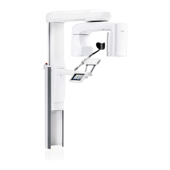
- Page 1 Planmeca Viso ™ user's manual 30005931...
-
Page 3: Table Of Contents
11.4 Selecting patient’s left or right side....................45 11.5 Selecting patient size........................47 11.6 Adjusting image volume position and size..................47 11.7 Selecting image resolution and Ultra Low Dose (ULD)..............49 11.8 Adjusting exposure values for current exposure................50 User's manual Planmeca Viso G7... - Page 4 12.3 Evaluating test results........................64 Help messages............................66 Error messages............................69 Cleaning and disinfection..........................70 15.1 Patient supports, patient handles and touch screen...............71 15.2 Other surfaces..........................73 Service..............................74 Disposal..............................75 Technical specifications..........................76 18.1 Technical data..........................76 18.2 Original manufacturer........................78 Planmeca Viso G7 User's manual...
- Page 5 Table of contents User's manual Planmeca Viso G7...
- Page 6 IEC 60364 - equipment is used according to the operating instructions. Planmeca pursues a policy of continual product development. Although every effort is made to produce up-to-date product documentation this publication should not be regarded as an infallible guide to current specifications. We reserve the right to make changes without prior notice.
-
Page 7: Introduction
• Planmeca Viso G7 NOTE This manual is valid for Planmeca Viso software version 1.1.1 or later. This software version is compatible with Planmeca Romexis software version 5.2.0.r or later. To check the software version of your X-ray unit, select Settings >... -
Page 8: Associated Documentation
User’s Manual • Installation Manual • Technical Manual These manuals are intended to be used in conjunction with the documentation for the Planmeca Romexis program. The Romexis package contains the following manuals: • User’s Manual • Technical Manual The original language of the manuals is English. -
Page 9: Product Registration
3 Product registration 3 Product registration To register your X-ray unit on Planmeca’s website: 1. Select Settings > About > 4300 Product Registration. 2. Do one of the following: • A QR (Quick Response) code is shown on the screen. If you have a QR code reader installed on your mobile device (e.g. -
Page 10: Symbols
To avoid risk of electric shock, this equipment must only be connected to a supply mains with protective earth. Electrostatic sensitive device (Standard IEC 60417) Warning, hot surface (Standard ISO 7010). General warning (Standard ISO 7010). Planmeca Viso G7 User's manual... -
Page 11: Safety Precautions
CAUTION Do not use the X-ray unit in an oxygen rich environment or in the presence of flammable anesthetics. CAUTION Never use a defective or damaged X-ray system. Contact your service technician for help. User's manual Planmeca Viso G7... - Page 12 Make sure that there is no object under the X-ray unit when you move the X- ray unit down. If something is in danger of becoming trapped, release the height adjusting slider immediately to stop the movement. Clear any obstruction before moving the X-ray unit again. Planmeca Viso G7 User's manual...
- Page 13 CBCT. NOTE Before taking an exposure, ask any female patient of childbearing age whether she might be pregnant. The X- ray unit is not intended for use on pregnant women. User's manual Planmeca Viso G7...
- Page 14 FOR US & CANADIAN USERS: The laser lights are class II laser products (21 CFR § 1040.10). NOTE FOR EUROPEAN USERS: The laser lights are class 1 laser products (Standard IEC / EN 60825-1: 2007). Planmeca Viso G7 User's manual...
- Page 15 Contact your service technician if you notice a decrease in image quality. NOTE If you take an exposure but the image does not appear in the Planmeca Romexis program, you can import the image manually into Romexis. Refer to the Planmeca Romexis User's Manual for details.
- Page 16 5 Safety precautions NOTE Do not touch the glass windows of the sensor. Fingerprints or other stains on the glass surface destroy image quality. Planmeca Viso G7 User's manual...
-
Page 17: Pediatric Use
"Control panel" on page 19 (Checking DAP index and ability to record other patient values) information, e.g. age (standard) Planmeca Romexis User's Manual (Entering date of birth and Generating X-ray log book) ULD (Ultra Low Dose) setting (optional) "Selecting image resolution and Ultra Low Dose (ULD)"... - Page 18 Estimated patient dosimetry covering pediatric "Control panel" on page 19 (Checking DAP size ranges (standard) values) Planmeca Romexis User's Manual (Generating X-ray log book) Quality control instructions including tests to "3D quality control" on page 60 ensure proper operation across a broad patient...
-
Page 19: Switching X-Ray System On
7.1 Switching X-ray unit on The on / off switch is located on the underside of the column top. 7.2 Switching 3D reconstruction PC on The on / off switch is located at the top of the computer. User's manual Planmeca Viso G7... -
Page 20: Main Parts
8 Main parts 8 Main parts 8.1 General view of X-ray system 1 X-ray unit 2 3D reconstruction PC 3 Planmeca Romexis program 4 Ethernet switch Planmeca Viso G7 User's manual... -
Page 21: General View Of X-Ray Unit
3 Patient supports (see section "Patient supports" on page 16) 4 Patient handles 5 Touch screen (see section "Control panel" on page 19) 6 Moving column 7 Stationary column 8 Emergency stop button (see section "Emergency stop button" on page 18) User's manual Planmeca Viso G7... -
Page 22: Patient Supports
8.3 Patient supports Rear head support Top head support Temple pads for children Fastening straps Support bars Bite piece (for panoramic exposures) Chin rest (for panoramic exposures) Chin cup Chin support (for panoramic exposures) 10 Adapter Planmeca Viso G7 User's manual... -
Page 23: Exposure Switch
X-ray system is ready for an exposure. During exposure a yellow radiation warning light illuminates on the exposure switch. It indicates that the X-ray unit is generating radiation. 1 Exposure switch 2 Exposure button User's manual Planmeca Viso G7... -
Page 24: Emergency Stop Button
All movements of the X-ray unit will be blocked and no radiation will be generated. A help message will appear on the control panel. Guide the patient away from the X-ray unit. Then release the emergency stop button. The X-ray unit will automatically restart. Planmeca Viso G7 User's manual... -
Page 25: Control Panel
You can use the control panel from 1. the touch screen that is part of the X-ray unit and 2. the virtual control panel that is integrated into the Planmeca Romexis program. The virtual control panel is shown on the computer screen when you have selected the patient and the exposure mode in Planmeca Romexis. - Page 26 8 Main parts • To make a selection on the virtual control panel in the Planmeca Romexis program, simply click your mouse on the function that you wish to use. The selected option is highlighted. To deselect an option, select the button or field again (or select another option if available).
- Page 27 To cancel a selection and close a pop-up window, select the red cross button. Home button To go to the home screen from another screen, select the home button. Scrolling lists To scroll a list up or down, slide your finger on the screen. User's manual Planmeca Viso G7...
- Page 28 3 Exposure time = Effective exposure time in seconds i.e. the time that the patient receives radiation 4 Scan time = Total scan time in seconds i.e. the time that you press the exposure button Planmeca Viso G7 User's manual...
- Page 29 You see these symbols in the bottom left corner of the screen when the demo mode is switched on. Additionally, a prohibition sign is shown on the top of the radiation symbol when you press the exposure button. User's manual Planmeca Viso G7...
- Page 30 8 Main parts Closing virtual control panel Click on this cross if you need to close the virtual control panel on the computer screen. Planmeca Viso G7 User's manual...
-
Page 31: Before Exposure
Attach these supports to the adapter. • You can use these supports for edentulous patients or for patients who are unable to bite. 9.1.1.2 Attaching chin supports for 3D exposures Attach this support to the adapter. User's manual Planmeca Viso G7... - Page 32 First attach the rear head support to the connector on the patient support base and then close the locking lever at the back. • To remove the rear head support, first release the locking lever and then pull the head support out. Planmeca Viso G7 User's manual...
- Page 33 • To remove the support bar, first turn it inwards and then pull it out. 9.1.1.5 Attaching top head support Slide the top head support onto the support bars. User's manual Planmeca Viso G7...
- Page 34 Slide the temple pads onto the head support as shown. Ensure that you slide the temple pads as far up as they will go. NOTE Use temple pads on both sides (not on one side only). Planmeca Viso G7 User's manual...
- Page 35 Do not overstretch the straps. The straps lose their elasticity if you pull them more than 50 mm (2 in.). Straps with a free length (i.e. when they are not stretched) of over 255 mm (10 in.) do not support the patient’s head firmly. User's manual Planmeca Viso G7...
-
Page 36: Preparing Planmeca Romexis
• 2D panoramic exposure • 3D exposure Refer to the Planmeca Romexis User’s Manual for details on Romexis functions. 9.2 Preparing patient Ask the patient to remove any spectacles, hearing aids, dentures, hairpins, and personal jewellery such as earrings, necklaces and piercings as these can produce shadows or reflections in the image. - Page 37 9 Before exposure NOTE High contrast objects, such as gold teeth or amalgam, may cause artefacts in the image. Place a protective lead apron over the patient’s back if required. User's manual Planmeca Viso G7...
-
Page 38: Panoramic Exposure
1. Guide the patient to the X-ray unit when you see this message. • The patient can sit or stand during the exposure. NOTE We recommend that you image patients with poor health in a sitting position. Planmeca Viso G7 User's manual... - Page 39 The upper and lower incisors must be in the groove in the bite piece. NOTE If you are using the chin support, position the patient so that the chin touches the top bar as shown. User's manual Planmeca Viso G7...
- Page 40 The midsagittal plane laser light is shown in the middle of the patient’s face. 5. If you are using the rear head support: • You can slide the rear head support up or down for optimal support of the patient's head. Planmeca Viso G7 User's manual...
- Page 41 You can adjust the head support by turning the adjusting knob at the top. 7. Select the forward button. • The sensor moves to the front. You see this message. The sensor contains digital cameras which stream live video of the patient’s head. User's manual Planmeca Viso G7...
- Page 42 The selected position is shown in the bottom right corner (e.g. 0 mm). 10. Check that the midsagittal plane light and the Frankfort plane reference line are still correctly positioned. Reposition them if necessary. Planmeca Viso G7 User's manual...
-
Page 43: Selecting Patient Size
The preset exposure values are shown in the following table. Factory presets for panoramic exposures PATIENT SIZE kV VALUE mAs VALUE Child (XS) Small adult (S) Medium-sized adult (M) Large adult (L) Extra large adult (XL) User's manual Planmeca Viso G7... -
Page 44: Taking A 2D Exposure
3. Select the green check mark button. 10.5 Taking a 2D exposure NOTE Make sure that you have selected the correct patient in the Planmeca Romexis program. 1. Select the forward button. Planmeca Viso G7... - Page 45 2. Ask the patient to swallow, place their tongue flat against the roof of the mouth and stay as still as possible. 3. Press and hold down the exposure button for the duration of the exposure. User's manual Planmeca Viso G7...
- Page 46 X-ray unit. • Select this button if you want to go to the home screen. 5. Release the patient from the head support. 6. Guide the patient away from the X-ray unit. Planmeca Viso G7 User's manual...
- Page 47 10 2D panoramic exposure 7. The image is shown on the computer screen. User's manual Planmeca Viso G7...
-
Page 48: Exposure
11.2 Selecting imaging program Select the 3D program you wish to use (e.g. 3D Dental > 3D Teeth). • The sensor moves to the back if it is not already there. You see this message. Planmeca Viso G7 User's manual... -
Page 49: Patient Positioning
3. Ask the patient to grasp the patient handles. 4. Position the patient’s head so that the patient’s midsagittal plane coincides with the midsagittal plane laser light. User's manual Planmeca Viso G7... - Page 50 The midsagittal plane laser light is shown in the middle of the patient’s face. 5. If you are using the rear head support: • You can slide the rear head support up or down for optimal support of the patient's head. Planmeca Viso G7 User's manual...
-
Page 51: Selecting Patient's Left Or Right Side
Refer to section "Attaching top head support" on page 27 for details. 7. Select the forward button. • The sensor moves to the front. You see this message. 11.4 Selecting patient’s left or right side NOTE This function is not available for the Skull program. User's manual Planmeca Viso G7... - Page 52 Use this button to select the side that you wish to expose. • The sensor moves to the selected side and an image of that side is shown on the screen. You see this message. Patient's left side selected Patient's right side selected Planmeca Viso G7 User's manual...
-
Page 53: Selecting Patient Size
You can use either or both views to adjust the volume position and size. NOTE The blue area is not an exact representation of the image volume. It is intended for visualization purposes only. User's manual Planmeca Viso G7... - Page 54 The ball turns red when you reach the limit value, i.e. when the volume diameter or height cannot be further adjusted in that direction. The selected volume size (diameter and height) is shown in the bottom right corner of the screen. Planmeca Viso G7 User's manual...
-
Page 55: Selecting Image Resolution And Ultra Low Dose (Uld)
3. Select the ULD (Ultra Low Dose) button if you want to take an exposure with a very low dose. The voxel size buttons turn green and show a small apple. 4. Select the green check mark button. NOTE The available options depend on the selected program. User's manual Planmeca Viso G7... -
Page 56: Adjusting Exposure Values For Current Exposure
Extra large adult (XL) Factory presets for voxel size 150 micrometres PATIENT SIZE kV VALUE mAs VALUE mAs VALUE WITH ULD Child (XS) Small adult (S) Medium-sized adult (M) 12.5 Large adult (L) Extra large adult (XL) Planmeca Viso G7 User's manual... -
Page 57: Selecting Artefact Removal Algorithm (Ara) And Patient Movement Correction (Calm)
1. Select this field to open a pop-up window. 2. Select this button to open another pop-up window. 3. Toggle the ARA (Artefact Removal Algorithm) button to select the setting you wish to use: • No artefact removal User's manual Planmeca Viso G7... -
Page 58: Taking Scout Views
4. Select the CALM (patient movement correction) button if you wish to minimize the effects of movements on the image. The Planmeca CALM function is an algorithm that detects patient movement during exposure and then compensates for the effects of the movement during image reconstruction. - Page 59 The scout views are automatically saved in the Planmeca Romexis program under 2D images (CBCT tab). NOTE Make sure that you have selected the correct patient in the Planmeca Romexis program. 1. Select this field to open a pop-up window.
- Page 60 Additionally, you hear a radiation warning tone and see a radiation warning symbol on the control panel. 7. If needed, you can now fine-adjust the volume position and size. Planmeca Viso G7 User's manual...
- Page 61 • The adjustment is indicated by different blue shades: • Dark blue area = Volume position and size before adjustment • Light blue area = Volume position and size after adjustment User's manual Planmeca Viso G7...
-
Page 62: Taking A 3D Exposure
11.11 Taking a 3D exposure NOTE Make sure that you have selected the correct patient in the Planmeca Romexis program. NOTE After scout views the X-ray system is automatically ready for a 3D exposure. - Page 63 You see this message. 2. Ask the patient to stay as still as possible. 3. Press and hold down the exposure button for the duration of the exposure(s). User's manual Planmeca Viso G7...
- Page 64 4. You see this message on the touch screen. • Select this button if you want to move the sensor to the back so that the patient can leave the X-ray unit. Planmeca Viso G7 User's manual...
- Page 65 ULD (Ultra Low Dose) button, you have to wait longer before the image appears. • If you took a skull exposure with two image volumes, you must accept the image stitching function in the Planmeca Romexis program. User's manual Planmeca Viso G7...
-
Page 66: Quality Control
A quality control test must be carried out on the X-ray unit once a month in order to ensure consistent image quality. A separate software program called Planmeca Device Tool QA has been installed on your computer for this purpose. -
Page 67: Test Procedure
1. Start the Device Tool QA program on your computer. 2. Select the Viso button. 3. On the next screen, select the • option Viso Production and • QA VISO button at the bottom of the screen. User's manual Planmeca Viso G7... - Page 68 7. You see this message when done. NOTE You may have to wait for a few minutes before the message appears. You see a blue spinning circle on the screen when the image is being processed. Planmeca Viso G7 User's manual...
- Page 69 10. Select the Next button at the bottom of the screen. 11. Take a third exposure as instructed in steps 5 and 6. 12. Select the Create report button at the bottom of the screen. User's manual Planmeca Viso G7...
-
Page 70: Evaluating Test Results
Recommended test Performance criteria frequency Monthly > 1 lp/mm (Modulation Transfer Function) Monthly Max. difference between measured average value and baseline value (Hounsfield unit) A: Acryl: 50 HU B: Aluminium: 200 HU C: Air: 50 HU Planmeca Viso G7 User's manual... - Page 71 If the problem persists, contact your service technician for help. NOTE In order to be able to compare the test results, it is essential to use the same equipment and accessories for both tests. User's manual Planmeca Viso G7...
-
Page 72: Help Messages
H130 Patient safety area Patient safety area violation detected. H131 Rear head support Rear head support movement detected. H132 Rear head support detached. H133 Remove the rear head support. H134 Adjust the rear head support. Planmeca Viso G7 User's manual... - Page 73 Imaging equipment is too low. H157 Imaging equipment movement timeout. H158 Imaging equipment position sensor not working properly. H159 Z column position sensor not working properly. H160 Imaging equipment is moving in wrong direction, check sensors and cables. User's manual Planmeca Viso G7...
- Page 74 Workstation communication failure. H193 Invalid scan settings. H194 CPU connection not established. H195 Request timed out while waiting for CPU to respond. H196 Version mismatch in communication interfaces. H197 Workstation communication disabled. H199 Video streaming failed. Planmeca Viso G7 User's manual...
-
Page 75: Error Messages
The X-ray unit will not accept any commands from the user until the error message is cleared. Guide the patient away from the X-ray unit. Then clear the message by selecting the green check mark button. User's manual Planmeca Viso G7... -
Page 76: Cleaning And Disinfection
NOTE Switch the X-ray unit off before cleaning and disinfection. NOTE Use a Planmeca approved cleaning agent and surface disinfectant. The products are categorised here as cleaning agents and / or disinfectants according to the information provided by the manufacturers. -
Page 77: Patient Supports, Patient Handles And Touch Screen
15 Cleaning and disinfection 15.1 Patient supports, patient handles and touch screen Wipe these parts after each patient using a Planmeca approved surface disinfectant. Use a Planmeca approved cleaning agent for cleaning stains and dirt if needed. Patient supports User's manual... - Page 78 15 Cleaning and disinfection Patient handles and touch screen NOTE These parts can be autoclaved at 134°C (273°F). They can be autoclaved at least up to 100 times. Planmeca Viso G7 User's manual...
-
Page 79: Other Surfaces
15 Cleaning and disinfection 15.2 Other surfaces Wipe the other surfaces regularly using a Planmeca approved surface disinfectant. Use a Planmeca approved cleaning agent for cleaning stains and dirt if needed. User's manual Planmeca Viso G7... -
Page 80: Service
16 Service 16 Service The X-ray unit must be checked by a qualified Planmeca service technician once a year or after every 10 000 exposures (if this is sooner). This will guarantee patient and user safety and ensure consistent image quality. -
Page 81: Disposal
17 Disposal In order to reduce the environmental load over the product’s entire lifecycle, Planmeca’s products are designed to be as safe as possible to manufacture, use and dispose of. Parts which can be recycled should always be taken to the appropriate processing centers, after hazardous waste has been removed. -
Page 82: Technical Specifications
Toshiba D-059SBR: 1‐14 mA ±10% SXR 130‐10‐0.5 SC: 1‐16 mA ±10% ProCeph Toshiba D-059SBR: 14 mA ±10% SXR 130-10‐0.5 SC: 16 mA ±10% mAs range min. / max. as indicated ±(10% + 0.2 mAs) Dose range and accuracy Planmeca Viso G7 User's manual... - Page 83 230 ‐ 240 V~ / 8A FF H 500 V Type 195100 ELU External fuse(s) 100 ‐ 220 V ~ / 16A min. - 20A max. T 250 V 230 ‐ 240 V ~ / 10A min. - 20A max. T 250 V User's manual Planmeca Viso G7...
-
Page 84: Original Manufacturer
8 ‐ 25 x 146 mm (0.31 ‐ 0.98 x 5.74 in.) Operating requirements for ProFace program Optimum colour temperature Approx. 6500 Kelvin Even and uniform lighting No bright lights 18.2 Original manufacturer PLANMECA Oy, Asentajankatu 6, FIN-00880 Helsinki, FINLAND Phone: +358 20 7795 500, www.planmeca.com Planmeca Viso G7 User's manual... - Page 86 Planmeca Oy | Asentajankatu 6 | 00880 Helsinki | Finland tel. +358 20 7795 500 | fax +358 20 7795 555 | sales@planmeca.com | www.planmeca.com...
Need help?
Do you have a question about the Viso G7 and is the answer not in the manual?
Questions and answers