Table of Contents
Advertisement
Advertisement
Table of Contents

Related Manuals for Planmeca Viso


Summary of Contents for Planmeca Viso
- Page 1 Planmeca Viso ™ user's manual 30005931 30005931...
- Page 2 IEC 60364 - equipment is used according to the operating instructions. Planmeca pursues a policy of continual product development. Although every effort is made to produce up-to-date product documentation this publication should not be regarded as an infallible guide to current specifications. We reserve the right to make changes without prior notice.
-
Page 3: Table Of Contents
Exposure switch........................... 19 Emergency stop button.........................19 Control panel..........................20 Before exposure............................27 Preparing X-ray system........................ 27 9.1.1 Attaching patient supports....................27 9.1.2 Preparing Planmeca Romexis..................33 Preparing patient.......................... 33 2D exposure............................. 34 10.1 2D dental programs........................34 10.2 Selecting imaging program......................35 10.3 Patient positioning........................ - Page 4 Component Information (4100)..................90 13.2.2 Archive (4200)......................91 13.2.3 Product Registration (4300)..................92 Help messages............................93 Error messages............................96 Cleaning and disinfection..........................97 16.1 Patient supports, patient handles and touch screen..............97 16.2 Other surfaces..........................100 Service..............................101 Disposal..............................102 Technical specifications..........................103 Planmeca Viso User's manual...
-
Page 5: Introduction
• Planmeca Viso G7 NOTE This manual is valid for Planmeca Viso software version 1.3.0 or later. This software version is compatible with Planmeca Romexis software version 6.3.0 or later. To check the software version of your X-ray unit, select Settings >... -
Page 6: Usage Environment
1 Introduction 1.2.1 Usage environment This X-ray unit is intended to be used in a professional healthcare environment such as dental offices, clinics and similar environments. Planmeca Viso User's manual... -
Page 7: Associated Documentation
User’s Manual • Installation Manual • Technical Manual These manuals are intended to be used in conjunction with the documentation for the Planmeca Romexis program. The Romexis package contains the following manuals: • User’s Manual • Technical Manual The original language of the manuals is English. -
Page 8: Product Registration
3 Product registration 3 Product registration About this task Follow these steps to register your X-ray unit on Planmeca's website. Steps 1. Select Settings > About > 4300 Product Registration. 2. Do one of the following: • If you have a QR (Quick Response) code reader installed on your mobile device (e.g. -
Page 9: Symbols
Refer to instruction manual/booklet (Standard ISO 7010). Emergency stop (Standard IEC 60417) Warning: Electricity (Standard ISO 7010). To avoid risk of electric shock, this equipment must only be connected to a supply mains with protective earth. Electrostatic sensitive device (Standard IEC 60417) User's manual Planmeca Viso... - Page 10 4 Symbols Warning, hot surface (Standard ISO 7010). General warning (Standard ISO 7010). Planmeca Viso User's manual...
-
Page 11: Safety Precautions
CAUTION Do not use the X-ray unit in an oxygen rich environment or in the presence of flammable anesthetics. CAUTION Never use a defective or damaged X-ray system. Contact your service technician for help. User's manual Planmeca Viso... - Page 12 30 cm (12 inches) to any part of the X-ray unit, including cables specified by the manufacturer. Otherwise, degradation of the performance of this equipment could result. Planmeca Viso User's manual...
- Page 13 CT or MR medical imaging should be used rather than CBCT. NOTE Before taking an exposure, ask any female patient of childbearing age whether she might be pregnant. The X- ray unit is not intended for use on pregnant women. User's manual Planmeca Viso...
- Page 14 NOTE FOR US & CANADIAN USERS: The laser lights are class II laser products (21 CFR § 1040.10). NOTE FOR EUROPEAN USERS: The laser lights are class 1 laser products (Standard IEC / EN 60825-1: 2007). Planmeca Viso User's manual...
- Page 15 Contact your service technician if you notice a decrease in image quality. NOTE Contact your service technician if you have taken an exposure but the image does not appear in the Planmeca Romexis program. You can import the last ten images manually into Planmeca Romexis. NOTE Do not handle liquids near or on the X-ray unit.
- Page 16 Portable mobile devices and other high frequency electromagnetic energy emitting devices used close to the X-ray system may affect the system’s performance. Diagnostic information of the X-ray image may be lost and unnecessary X-ray dose to the patient may result. Planmeca Viso User's manual...
-
Page 17: Pediatric Use
"Control panel" on page 20 (Checking DAP dose index and ability to record other patient values) information, e.g. age (standard) Planmeca Romexis User's Manual (Entering date of birth and Generating X-ray log book) ULD (Ultra Low Dose) setting (optional) "Selecting image resolution, Ultra Low Dose (ULD) and ProFace"... - Page 18 Estimated patient dosimetry covering pediatric "Control panel" on page 20 (Checking DAP size ranges (standard) values) Planmeca Romexis User's Manual (Generating X-ray log book) Quality control instructions including tests to "3D quality control" on page 76 ensure proper operation across a broad patient...
-
Page 19: Switching X-Ray System On
7.1 Switching X-ray unit on The on / off switch is located on the underside of the column top. 7.2 Switching 3D reconstruction PC on The on / off switch is located at the top of the computer. User's manual Planmeca Viso... -
Page 20: Main Parts
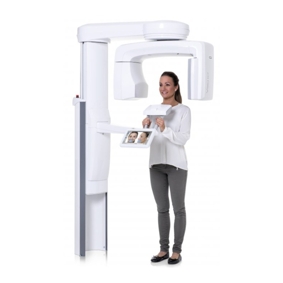
8 Main parts 8 Main parts 8.1 General view of X-ray system 1 X-ray unit 2 3D reconstruction PC 3 Planmeca Romexis program 4 Ethernet switch Planmeca Viso User's manual... -
Page 21: General View Of X-Ray Unit
3 Patient supports (see section "Patient supports" on page 18) 4 Patient handles 5 Touch screen (see section "Control panel" on page 20) 6 Moving column 7 Stationary column 8 Emergency stop button (see section "Emergency stop button" on page 19) User's manual Planmeca Viso... -
Page 22: Patient Supports
Top head support (optional) Temple pads for children (optional) Fastening straps (optional) Support bars Bite piece (for panoramic exposures) Chin rest (for panoramic exposures) Chin cup Chin support (for panoramic exposures) 10 Adapter 11 Connector plugs Planmeca Viso User's manual... -
Page 23: Exposure Switch
All movements of the X-ray unit will be blocked and no radiation will be generated. A help message will appear on the control panel. Guide the patient away from the X-ray unit. Then release the emergency stop button. The X-ray unit will automatically restart. User's manual Planmeca Viso... -
Page 24: Control Panel
NOTE Do not use sharp objects to operate the touch screen. To make a selection on the virtual control panel in the Planmeca Romexis program, simply click your mouse on the function that you wish to use. The selected option is highlighted. To deselect an option, select the button or field again (or select another option if available). - Page 25 NOTE The control panel display varies depending on which Viso model is in use. The control panel pictures used in this manual are example images only and may not correspond to, for example, the Planmeca Viso G5 display.
- Page 26 To accept a selection, select the green check mark button. Cancel button To cancel a selection and close a pop-up window, select the red cross button. Home button To go to the home screen from another screen, select the home button. Planmeca Viso User's manual...
- Page 27 The length of the blue section indicates the length of the movement: the longer the section is, the more the C-arm will move. The circle disappears when the C-arm has reached the new position. User's manual Planmeca Viso...
- Page 28 The actual DAP value is shown after the exposure. Patient name When a patient is selected in Planmeca Romexis, their name and date of birth is visible on the top right corner of the control panel for the duration of the imaging.
- Page 29 You see these symbols in the bottom left corner of the screen when the demo mode is switched on. Additionally, a prohibition sign is shown on the top of the radiation symbol when you press the exposure button. User's manual Planmeca Viso...
- Page 30 8 Main parts Closing virtual control panel Click on this cross if you need to close the virtual control panel on the computer screen. Planmeca Viso User's manual...
-
Page 31: Before Exposure
3. Release the trigger. 9.1.1.2 Removing adapter About this task Follow these instructions to remove the adapter. Steps 1. Press the trigger down and hold. 2. Remove the adapter by sliding it downwards in an upright position. User's manual Planmeca Viso... - Page 32 9.1.1.4 Attaching chin supports for 3D exposures Steps 1. Attach the support shown below to the adapter. 9.1.1.5 Attaching rear head support Steps 1. Attach the rear head support to the connector on the patient support base. Planmeca Viso User's manual...
- Page 33 1. Release the locking lever. 2. Pull out the head support. 9.1.1.7 Attaching support bars About this task Follow these steps to attach the support bars to the patient support base. Steps 1. Remove the plugs covering the connectors. User's manual Planmeca Viso...
- Page 34 Results The support bar is locked into place when you hear a clicking sound. 9.1.1.8 Removing support bars Steps 1. Pull the support bar out. 2. Cover the connectors with the silicone plugs. Planmeca Viso User's manual...
- Page 35 3. You can use temple pads when you take exposures of children or patients with a small head. Slide the temple pads onto the head support as shown. Ensure that you slide the temple pads as far up as they will go. User's manual Planmeca Viso...
- Page 36 Do not overstretch the straps. The straps lose their elasticity if you pull them more than 50 mm (2 in.). Straps with a free length (i.e. when they are not stretched) of over 255 mm (10 in.) do not support the patient’s head firmly. Planmeca Viso User's manual...
-
Page 37: Preparing Planmeca Romexis
1. Select the patient. 2. Right-click on the patient and select Capture followed by Pan Exp for 2D exposure or Capture for 3D exposure. Refer to the Planmeca Romexis 6 User’s Manual for details on Romexis functions. 9.2 Preparing patient... -
Page 38: Exposure
The Bitewing program produces bitewing images from premolar and molar areas including parts of maxilla, mandible and rami. The bottom of the maxillary sinus as well as the mandibular canal and the mental foramen are also visible. Planmeca Viso User's manual... -
Page 39: Selecting Imaging Program
The 2D View program enables a large single-shot 2D exposure taken with the imaging arm, generating clear 2D projections of the maxillofacial region as shown in the example below. 1 Planmeca Viso G5 projection example results 2 Planmeca Viso G7 projection example results 10.2 Selecting imaging program Steps 1. -
Page 40: Patient Positioning
NOTE The message does not display if the fast forward option is selected. The patient can sit or stand during the exposure. NOTE We recommend that you image patients with poor health in a sitting position. Planmeca Viso User's manual... - Page 41 NOTE If you are using the chin support or chin cup, use for example a cotton roll between the patient's teeth to ensure that the upper and lower incisors do not make contact. User's manual Planmeca Viso...
- Page 42 The midsagittal plane laser light is shown in the middle of the patient’s face. 5. If you use the rear head support, you can slide it up or down for optimal support of the patient's head. Planmeca Viso User's manual...
- Page 43 Carefully position the patient’s Frankfort plane so that it is parallel to the Frankfort plane reference line. Use the height adjusting slider on the touch screen to adjust the tilt of the patient’s head. The patient’s back and neck must be straight. User's manual Planmeca Viso...
- Page 44 Position the apices of the patient’s upper central incisors within the image layer of the X-ray unit: 9. Optionally, activate the Panoramic segmentation and select the segments for exposure. • Select the Segmentation button from the left bottom corner. Planmeca Viso User's manual...
- Page 45 10 2D exposure • Use the segmentation buttons to select the active exposure areas. User's manual Planmeca Viso...
-
Page 46: Selecting Patient Size
M = Medium-sized adult • L = Large adult • XL = Extra large adult The preset exposure values are shown below the patient sizes. NOTE Selecting child patient (XS) will automatically reduce the exposure area. Planmeca Viso User's manual... -
Page 47: Adjusting Exposure Values For Current Exposure
1. Select this field (1) to open a pop-up window. 2. Use the minus or plus signs (2) to set the exposure values you wish to use. To improve the image contrast, reduce the kV value. To reduce the radiation dose, reduce the mAs value. User's manual Planmeca Viso... -
Page 48: Taking 2D Exposure
3. Select the green check mark button. 10.6 Taking 2D exposure 10.6.1 2D Panoramic exposure Before you begin Make sure that you have selected the correct patient in the Planmeca Romexis program. About this task Follow these steps to take a 2D Panoramic exposure. - Page 49 Do not release the exposure button before the end of the exposure. NOTE Maintain audio and visual contact with the patient and X-ray unit during exposure. If the C-arm stops moving during exposure, or moves in an erratic way, release the exposure button immediately. User's manual Planmeca Viso...
-
Page 50: View Exposure
The image is shown on the computer screen. 10.6.2 2D View exposure Before you begin Make sure that you have selected the correct patient in the Planmeca Romexis program. About this task Follow these steps to take a 2D View exposure. - Page 51 X-ray system is getting ready for an exposure. You see this message. NOTE Move to a protected area. The green lights stop flashing and stay on continuously when the X-ray system is ready for an exposure. You see this message. User's manual Planmeca Viso...
- Page 52 Do not release the exposure button before the end of the exposure. NOTE Maintain audio and visual contact with the patient and X-ray unit during exposure. If the C-arm stops moving during exposure, or moves in an erratic way, release the exposure button immediately. Planmeca Viso User's manual...
- Page 53 Select this button if you want to go to the home screen. 7. Release the patient from the head support. 8. Guide the patient away from the X-ray unit. Results The image displays on the computer screen. User's manual Planmeca Viso...
-
Page 54: Exposure
11 3D exposure 11 3D exposure 11.1 3D dental programs 3D dental programs include: • 3D programs • 3D ENT programs • Special programs 3D programs 3D ENT programs Planmeca Viso User's manual... -
Page 55: Preset Volume Sizes
When a program is selected, the device selects the following settings for the volume. NOTE If the volume size has been adjusted (is different than default), patient size change (adult > XS, child) does not change the volume size. 3D programs, Planmeca Viso G7 Program Preset volume Volume range Note... - Page 56 11 3D exposure 3D ENT programs, Planmeca Viso G7 Program Preset volume Volume range Note size Nose Ø80 × 80 mm Ø70 × 50 mm – Ø120 × 100 mm 10 mm steps Sinus Ø130 × 130 mm Ø100 × 100 mm – Ø160 × 160 mm...
-
Page 57: Selecting Imaging Program
1. Select the 3D program you want to use, for example 3D > 3D Teeth. NOTE When taking a 3D image for jaw tracking with the Planmeca 4D Jaw Planmeca Viso 4D Jaw Motion system, select the Face program. See Motion user's manual for more information. -
Page 58: Patient Positioning
2. Use the height adjusting slider on the touch screen to move the X-ray unit up or down until the chin cup is approximately level with the patient’s lower jaw. 3. Ask the patient to grasp the patient handles. Planmeca Viso User's manual... - Page 59 You can adjust the head support by turning the adjusting knob at the top. • You can use fastening straps for additional head support if needed. Refer to section "Attaching top head support" on page 31 for details. User's manual Planmeca Viso...
-
Page 60: Selecting Patient's Left Or Right Side
About this task Follow these instructions to select the patient's left or right side. NOTE This function is not available for the Skull program. The sensor contains digital cameras which stream live video of the patient’s head. Planmeca Viso User's manual... -
Page 61: Selecting Patient Size
The sensor moves to the selected side and an image of that side is shown on the screen. You see this message. Patient's left side selected Patient's right side selected 11.5 Selecting patient size Steps 1. Use the button shown below to select the patient size. • XS = Child User's manual Planmeca Viso... -
Page 62: Adjusting Image Volume Position And Size
The blue area can be moved in any direction. 2. Adjust the volume size on the touch screen smaller or larger by using pinch gestures (1), or holding your mouse cursor (virtual control panel) or Planmeca Viso User's manual... - Page 63 With Tooth program you can alternatively use the button shown below when you select the image volume position. Select the position from the pop-up window that appears and confirm by selecting the green check mark button. User's manual Planmeca Viso...
-
Page 64: Selecting Image Resolution, Ultra Low Dose (Uld) And Proface
The exposure values have been preset at the factory for each patient size, image resolution and ULD (Ultra Low Dose) setting. The preset exposure values are average values and they are only meant to guide the user. The preset exposure values are shown in the following tables. Planmeca Viso User's manual... - Page 65 1. Select this field (1) to open a pop-up window. 2. Use the minus or plus signs (2) to set the exposure values you wish to use. To improve the image contrast, reduce the kV value. To reduce the radiation dose, reduce the mAs value. User's manual Planmeca Viso...
-
Page 66: Selecting Artefact Removal Algorithm (Ara) And Patient Movement Correction (Calm)
(patient size XS) or restless patients. NOTE The Planmeca CALM algorithm is for use only on live patients and is not recommended for use, for example, in imaging involving an inorganic sample or QA phantom attachment. -
Page 67: Taking Scout Views
The scout views are automatically saved in the Planmeca Romexis program under 2D images (CBCT tab). Make sure that you have selected the correct patient in the Planmeca Romexis program. NOTE The scout view function can yield results for Teeth, Tooth and Jaw programs that look different to the scouts for Face and Sinus programs. - Page 68 Move to a protected area. The green lights stop flashing and stay on continuously when the X-ray system is ready for an exposure. The following message displays. 5. Ask the patient to stay as still as possible. Planmeca Viso User's manual...
- Page 69 7. If needed, you can now fine-adjust the volume position and size. • To fine-adjust the volume position, use your mouse cursor (virtual control panel) or finger (touch screen) to move the blue area. The blue area can be moved in any direction. User's manual Planmeca Viso...
- Page 70 The selected volume size (diameter and height) is shown in the bottom right corner of the screen. Planmeca Viso User's manual...
-
Page 71: Taking 3D Exposure
11.11 Taking 3D exposure Before you begin Make sure that you have selected the correct patient in the Planmeca Romexis program. NOTE After scout views the X-ray system is automatically ready for a 3D exposure. - Page 72 X-ray system is getting ready for an exposure. You see this message. NOTE Move to a protected area. The green lights stop flashing and stay on continuously when the X-ray system is ready for an exposure. You see this message. Planmeca Viso User's manual...
- Page 73 (1) shows the capture progress and the slider below the second image (2) allows you to view the captured frames from different angles. NOTE Do not release the exposure button before the end of the exposure(s). User's manual Planmeca Viso...
- Page 74 5. You see this message on the touch screen. • Select this button if you want to retake the exposure with the same settings. • Select this button if you want to go to the home screen. Planmeca Viso User's manual...
- Page 75 ULD (Ultra Low Dose) button, you have to wait longer before the image appears. If you took a skull exposure with two image volumes, you must accept the image stitching function in the Planmeca Romexis program. If the ProFace option was selected, the image processing takes some extra time.
-
Page 76: Taking 3D Face Photo
Select the ProFace program from the main page by selecting Special Programs > ProFace. For more information, see section "3D dental programs" on page 50. Make sure that you have selected the correct patient in the Planmeca Romexis program. Steps 1. - Page 77 Maintain audio and visual contact with the patient and X-ray unit during exposure. If the C-arm stops moving during exposure, or moves in an erratic way, release the exposure button immediately. 5. The image generates. This may take several minutes. User's manual Planmeca Viso...
- Page 78 • Select this button if you want to go to the home screen. 7. Remove the fastening straps (if used). Release the patient from the head support. 8. Guide the patient away from the X-ray unit. Planmeca Viso User's manual...
- Page 79 11 3D exposure Results The image is shown on the computer screen. User's manual Planmeca Viso...
-
Page 80: Quality Control
Device Tool QA program, read this section carefully before proceeding. CAUTION In the Device Tool, for the Planmeca 3D QA, it is possible to run multiple calibrations, i.e. select all 3D QA calibrations to be run in a row. If the multiple calibration is used, be extra careful with the following issues: •... -
Page 81: Running Qa Test
1. Attach the 3D QA phantom to the patient support base. 2. Switch on the X-ray unit. 3. Start the Device Tool QA in the clinic computer. 4. From the Device Tool launcher, select the VISO (left) option. User's manual Planmeca Viso... - Page 82 12 3D quality control 5. Click the QA button. 6. Select the test type Planmeca QA from the options. 7. Click the Start button to continue. Planmeca QA tests consists of the following test: • QA 3D - C-Arm Center •...
- Page 83 The following image view appears. 12. Select the QA 3D - Middle Arm Offset from the calibration task list and click the Start button. 13. Press the exposure button to take the exposure. CAUTION Protect yourself from radiation. User's manual Planmeca Viso...
- Page 84 On the report page, you can select which of the QA tests you want to include in the report. 15. Once your selections are ready, click Create Report. The report opens in a new browser window. For more information on the test results, see section "Post-test process" on page 81. Planmeca Viso User's manual...
-
Page 85: Post-Test Process
After successful QA test, remove the 3D QA phantom from the patient support table. QA test fails If the QA test fails, the unit is not correctly adjusted and calibrated. Contact your service technician for adjustment and calibration assistance. User's manual Planmeca Viso... -
Page 86: Settings
Settings that can be entered by service personnel only (password required): • Technical To return to the main screen, select the settings symbol at the top left corner. 13.1 User settings 13.1.1 Language (1100) About this task Follow these steps to change language. Planmeca Viso User's manual... -
Page 87: Operational Settings (1300)
3. Select the green check mark button. 13.1.2 Operational Settings (1300) 13.1.2.1 Mode (1310) Steps 1. Select User > 1300 Operational Settings > 1310 Mode. 2. Select the mode you wish to use: • 1311 Demo Mode User's manual Planmeca Viso... - Page 88 3. Select the green check mark button. 13.1.2.2 Scout Settings (1320) Steps 1. Select User > 1300 Operational Settings > 1320 Scout Settings. 2. Select the default scout setting in the 3D Tooth program. • Anatomical Planmeca Viso User's manual...
-
Page 89: Network Settings (1400)
1. Select User > 1400 Network Settings. 2. Select the network settings you wish to view. 3. Select the green check mark button. NOTE Only a service technician or local administrator may change the network settings. User's manual Planmeca Viso... -
Page 90: Testing Routines (1500)
1. Select User > 1500 Testing Routines > 1520 3D Test Exposure. 2. Use the - or + button to set the exposure values you wish to use. 3. Select the SET button. 4. Move to a protected area. Planmeca Viso User's manual... - Page 91 You can press and hold down the exposure button for the whole duration of the process or lift your thumb from the exposure button when the word Wait appears. NOTE The seasoning process takes several minutes. After a successful process the message OK displays. User's manual Planmeca Viso...
-
Page 92: Exposure Values (1600)
The values can be adjusted as follows: • 5 kV increments for 3D • 2 kV increments for Panoramic NOTE The mA adjustment increments are measured according to a decimal scale with divisions proportioned to the relevant mA measures. Planmeca Viso User's manual... -
Page 93: Licences (1700)
3. Enter the licence code that you have received for this licence on this X-ray unit. 4. Select the green check mark button. 5. Repeat for another program licence if needed. 6. Select the green check mark button. User's manual Planmeca Viso... -
Page 94: About
Information to view the set-up or current software versions of the X-ray unit. To view software build information: Select About > 4100 Component Information > Show Detailed Build Info to view details about the software build. Planmeca Viso User's manual... -
Page 95: Archive (4200)
Select About > 4200 Archive > 4210 Error History to view a list of the error messages that have been generated by the X- ray unit. The errors are shown in chronological order with the latest error message on top. User's manual Planmeca Viso... -
Page 96: Product Registration (4300)
To view exposure statistics: Select About > 4200 Archive > 4220 Exposure Statistics to view statistical data about the X-ray unit. 13.2.3 Product Registration (4300) For more information on product registration, see section "Product registration" on page 4. Planmeca Viso User's manual... -
Page 97: Help Messages
Memory Not enough memory on imaging There is not enough memory workstation for this imaging. allocated in the imaging workstation (e.g. Planmeca Romexis) for the selected imaging program. E.g. the skull program with volume size 300x300 requires 32 GB memory in the imaging workstation. - Page 98 Imaging equipment is too low. H157 Imaging equipment movement timeout. H158 Imaging equipment position sensor not working properly. H159 Z column position sensor not working properly. H160 Imaging equipment is moving in wrong direction, check sensors and cables. Planmeca Viso User's manual...
- Page 99 Exposed image data exists in reconstruction PC with the dataset ID given in the error message. The image can be brought into the Planmeca Romexis with the Redo 3D reconstructions command. H189 The screen was touched during Exposure was interrupted.
-
Page 100: Error Messages
The X-ray unit will not accept any commands from the user until the error message is cleared. Guide the patient away from the X-ray unit. Then clear the message by selecting the green check mark button. Planmeca Viso User's manual... -
Page 101: Cleaning And Disinfection
Contact your service technician for help if sprays, liquids or foams enter the system. 16.1 Patient supports, patient handles and touch screen Wipe these parts after each patient using a Planmeca approved surface disinfectant. Use a Planmeca approved cleaning agent for cleaning stains and dirt if needed. User's manual Planmeca Viso... - Page 102 16 Cleaning and disinfection Patient supports Planmeca Viso User's manual...
- Page 103 16 Cleaning and disinfection Patient handles and touch screen NOTE These parts can be autoclaved at 134°C (273°F). They can be autoclaved at least up to 100 times. User's manual Planmeca Viso...
-
Page 104: Other Surfaces
16 Cleaning and disinfection 16.2 Other surfaces Wipe the other surfaces regularly using a Planmeca approved surface disinfectant. Use a Planmeca approved cleaning agent for cleaning stains and dirt if needed. Planmeca Viso User's manual... -
Page 105: Service
17 Service 17 Service The X-ray unit must be checked by a qualified Planmeca service technician once a year or after every 10 000 exposures (if this is sooner). This will guarantee patient and user safety and ensure consistent image quality. -
Page 106: Disposal
18 Disposal 18 Disposal In order to reduce the environmental load over the product’s entire lifecycle, Planmeca products are designed to be as safe as possible to dispose of. Planmeca products fulfil the requirements of Directives 2011/65/EU (RoHS) and 2012/19/EU (WEEE). -
Page 107: Technical Specifications
/ max. as indicated ±(10% + 0.2 mAs) Dose range and accuracy Dose range min. / max. as indicated on system user interface. Accuracy of dosimetric indication (DAP, CTDI): ±35% Linearity of radiation output User's manual Planmeca Viso... - Page 108 100 ‐ 220 V ~ / 16A min. - 20A max. T 250 V 230 ‐ 240 V ~ / 10A min. - 20A max. T 250 V Battery Lithium battery: 3V, CR2032, Panasonic / Varta Max. weight Base unit 165 kg (364 lb) ProCeph 20 kg (44 lb) Planmeca Viso User's manual...
- Page 109 Flat panel pixel size Planmeca Viso G5: 127 μm Planmeca Viso G7: 139 µm Flat panel active surface Planmeca Viso G5: 157.5 x 157.5 mm (6.20 x 6.20 in.) Planmeca Viso G7: 299.7 x 246.3 mm (11.80 x 9.70 in.)
- Page 112 Planmeca Oy | Asentajankatu 6 | 00880 Helsinki | Finland tel. +358 20 7795 500 | fax +358 20 7795 555 | sales@planmeca.com | www.planmeca.com...
Need help?
Do you have a question about the Viso and is the answer not in the manual?
Questions and answers