Dräger Fabius plus Instructions For Use Manual
Anesthesia workstation
Hide thumbs
Also See for Fabius plus:
- Instructions for use manual (224 pages) ,
- Supplement manual (49 pages) ,
- Supplement to instructions for use (142 pages)

Related Manuals for Dräger Fabius plus


Summary of Contents for Dräger Fabius plus
- Page 1 Instructions for use Fabius plus Anesthesia workstation WARNING Software 3.n To properly use this medical device, read and comply with these instructions for use.
- Page 2 Use of terms Consecutive numbers indicate steps of action, with the numbering restarting with "1" for each – The product Fabius plus is also referred to as new sequence of actions. Fabius. Bullet points indicate individual actions or dif- –...
- Page 3 Users Experts must have the necessary knowledge and experience with complex maintenance work on the Users are persons who use the product in product. accordance with its intended use. Instructions for use Fabius plus SW 3.n...
- Page 4 Abbreviations and symbols Explanations can be found in the sections ''Abbreviations'' and ''Symbols'' in chapter ''Symbols''. Instructions for use Fabius plus SW 3.n...
-
Page 5: Table Of Contents
The MEDIBUS and Vitalink protocols....19 Checking the readiness for operation....88 Overview............20 Operation ............89 Fabius plus as trolley version (front view) ..21 Standby page after start-up......90 Compact breathing system COSY (top view) .. 22 Setting the fresh-gas flow........ 90 Power supply unit for COSY heating (front Setting the anesthetic gas concentration .. - Page 6 Device outlets..........207 Essential performance characteristics..... 208 EMC declaration..........209 Device combinations ........214 Connections to IT networks......215 Illustrations ............216 Annex ............. 218 Form for daily checkout and pre-use checkout 219 Instructions for use Fabius plus SW 3.n...
- Page 7 Safe coupling with electrical equipment ..10 Patient safety........... 10 Patient monitoring..........10 Information on electromagnetic compatibility .. 11 Installing accessories ........11 Keeping the instructions for use ...... 11 Training............11 Product-specific safety information .... 12 Instructions for use Fabius plus SW 3.n...
-
Page 8: For Your Safety And That Of Your Patients
CAUTION statements throughout these instructions for use and all statements on medical device labels. Failure to observe these safety information statements constitutes a use of the medical device that is inconsistent with its intended use. Instructions for use Fabius plus SW 3.n... -
Page 9: Accessories
Risk of explosion and fire This medical device is neither approved nor certified for use in areas where oxygen concentrations greater than 25 Vol%, combustible or explosive gas mixtures are likely to occur. Instructions for use Fabius plus SW 3.n... -
Page 10: Safe Coupling With Electrical Equipment
Medical device modification or misuse can be dangerous. CAUTION Risk of patient injury Do not make therapeutic decisions based solely on individual measured values and monitoring parameters. Instructions for use Fabius plus SW 3.n... -
Page 11: Information On Electromagnetic Compatibility
Only operate radio frequency devices at a Training sufficient safety clearance of at least 20 cm (7.9 in). User training is offered by the responsible Dräger organization, see www.draeger.com. Instructions for use Fabius plus SW 3.n... -
Page 12: Product-Specific Safety Information
During operation the medical device can move accidentally. WARNING Activate the castor brakes. Risk of device failure The device can fail if the power supply is interrupted. Always connect the device on an uninterruptible power supply. Instructions for use Fabius plus SW 3.n... - Page 13 (12 – Do not use cyclopropane or ether. feet). This facilitates fast recognition and response in the event of an alarm. Instructions for use Fabius plus SW 3.n...
- Page 14 Do not use the anesthesia workstation at an inclination over 1°. NOTE The device software of Fabius must be installed by experts. Dräger recommends having the software installation performed by DrägerService. Instructions for use Fabius plus SW 3.n...
-
Page 15: Application
Application Application Intended use ..........16 Indications/Contraindications ...... 17 Indications ............17 Contraindications..........17 Further information on application....18 Environment of use.......... 18 The MEDIBUS and Vitalink protocols ..19 Instructions for use Fabius plus SW 3.n... -
Page 16: Intended Use
Risk due to the accumulation of acetone in the patient Do not perform low-flow anesthesia on patients with ketoacidosis or patients under the influence of alcohol. The risk of accumulation of acetone in the patient increases in such cases. optional Instructions for use Fabius plus SW 3.n... -
Page 17: Indications/Contraindications
Patient status must be continuously monitored for potential changes. NOTE Fabius applies medical gases such as O or volatile anesthetic agents. For contraindications to the applied medical gases, strictly observe the instructions for use of the medical gas. Instructions for use Fabius plus SW 3.n... -
Page 18: Further Information On Application
Otherwise, there is a risk of CO formation. Do not use Fabius in the following environments: – Outside of massive buildings – In intensive care units – During patient transport – In vehicles, airplanes, or helicopters Instructions for use Fabius plus SW 3.n... -
Page 19: The Medibus And Vitalink Protocols
The system must meet the requirements of standards IEC 60601-1-1 and IEC 60601-1-2, or of IEC 60601-1:2005 for medical electrical equipment. Instructions for use Fabius plus SW 3.n... -
Page 20: Overview
Overview Overview Fabius plus as trolley version (front view) . 21 Compact breathing system COSY (top view) ............... 22 Power supply unit for COSY heating (front view) ............... 23 Power supply unit for COSY heating (rear view) ............... 24 Rear view............25 Pin-index connection ........ -
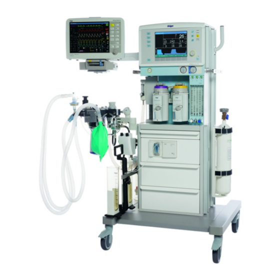
Page 21: Fabius Plus As Trolley Version (Front View)
Overview Fabius plus as trolley version (front view) plus A Ventilator control panel (settings for ventilation H Drawers parameters and airway monitoring) Locking brake B Screen J Power supply unit for COSY breathing system C Pressure gauges for gas cylinders (O... -
Page 22: Compact Breathing System Cosy (Top View)
E Flow-sensor guard or COSY guard (not illustrated) F Expiratory port G Connection for breathing bag H Inspiratory port Inspiratory valve J Fresh gas decoupling valve K Connection for APL bypass valve optional Instructions for use Fabius plus SW 3.n... -
Page 23: Power Supply Unit For Cosy Heating (Front View)
Overview Power supply unit for COSY heating (front view) A LED indicator for COSY heating B On/Off switch C Fuse Instructions for use Fabius plus SW 3.n... -
Page 24: Power Supply Unit For Cosy Heating (Rear View)
Overview Power supply unit for COSY heating (rear view) A Power inlet B LED indicator for power supply C Cable clamp Instructions for use Fabius plus SW 3.n... -
Page 25: Rear View
100 (bar) A Gas cylinder H Connection for ventilator hose B Pin-index connection C Power inlet with main fuses D On/Off switch E Battery fuse F Potential equalization pin G Interface panel optional Instructions for use Fabius plus SW 3.n... -
Page 26: Screw Connections
100 (bar) x 100 (bar) A Connections for compressed gas hoses of gas cylinders with O and N O, or O and Air (screw connections) B Connections for central supply hoses C Gas cylinders Instructions for use Fabius plus SW 3.n... -
Page 27: Interface Panel
Overview Interface panel A COM 1 port B Connection for PEEP hose C Connection for APL hose D Socket for O sensor E Socket for airway pressure sensor F Socket for flow sensor Instructions for use Fabius plus SW 3.n... -
Page 28: Vaporizer
Dräger recommends using only anesthetic vaporizers that are listed in the list of accessories. More information can be found in the respective instructions for use of the anesthetic vaporizers used. Instructions for use Fabius plus SW 3.n... -
Page 29: Ceiling-Mounted Version (Optional)
If the medical device is used in a tipped position, anesthesia workstation is not placed on a trolley, parts can be damaged or their function can be (see chapter ''Fabius plus as trolley version (front comprised. view)'' on page 21), but rather on the mount of a ceiling supply unit. -
Page 30: Wall-Mounted Version (Optional)
(see chapter ''Fabius plus as trolley version personal damage may occur. (front view)'' on page 21), but rather on a mount on –... -
Page 31: Supplemental O
After the O insufflation is ended, the flow control valve of the supplementary O delivery must be completely closed: Turn the flow control valve (A) clockwise to the final position stop. ASTM F1850-22(2005) §76 Instructions for use Fabius plus SW 3.n... -
Page 32: Apl Valve
ManSpont mode or is bypassed. Different settings can be made on the APL valve adjustment knob: – Change between manual ventilation (Man) and spontaneous breathing (Spont) – Setting of the maximum airway pressure for manual ventilation Instructions for use Fabius plus SW 3.n... -
Page 33: Interfaces
– If the permissible value is exceeded, disconnect the devices from the MEDIBUS interface. – Fabius plus – Breathing gas monitor (Vamos) 1 Connect the breathing gas monitor to COM 1 (A). Instructions for use Fabius plus SW 3.n... -
Page 34: External Fresh-Gas Outlet
Fabius do not correspond to the values for the patient connected to external fresh-gas outlet as they are based on measurements taken at the compact breathing system. When using the external fresh-gas outlet, change into the Standby mode. Instructions for use Fabius plus SW 3.n... -
Page 35: Using The External Fresh-Gas Outlet As A Common Gas Outlet
B Long fresh-gas hose (on Fabius) E Sample line C Short fresh-gas hose (on compact breathing F Non-rebreathing system (e.g., Bain) system) D Compact breathing system E Sample line F Non-rebreathing system (e.g., Bain) optional Instructions for use Fabius plus SW 3.n... -
Page 36: Abbreviations
Respiratory rate PLAT Plateau pressure Freq Min Mandatory minimal respiratory rate in Pressure Support mode PMAX Pressure limitation pounds per square inch High-frequency SIMV Synchronized Intermittent Man- Hectopascal datory Ventilation Insp Flow Inspiratory flow Instructions for use Fabius plus SW 3.n... - Page 37 Trigger Trigger UMDNS Universal Medical Device Nomenclature System, nomen- clature for medical devices Universal Serial Bus, computer interface Tidal volume ∆PPS Differential pressure of the pres- sure support in Pressure Sup- port mode Instructions for use Fabius plus SW 3.n...
-
Page 38: Symbols
Read the flow at the center of the float. Serial number Order number Non-rebreathing system Instructions for use Fabius plus SW 3.n... - Page 39 Socket for O sensor Socket for flow sensor Socket for airway pressure sen- Ventilator connection Fuse Do not oil! Close menu Key for access to alarm limits Key to call up main screen Instructions for use Fabius plus SW 3.n...
-
Page 40: Product Labels
''Technical data''. max. 280 kg Wall-mounted version / ceiling-mounted version: nom. 69 kg Observe the weight of the nominal configuration and the total permissible weight, see ''Technical max. 125 kg data''. Instructions for use Fabius plus SW 3.n... -
Page 41: Operating Concept
Fresh-gas delivery (version for 3 gases)..47 LED indicators ..........48 LEDs for operating status ........ 48 LEDs for alarm status ........48 Color coding for anesthetic agents and medical gases ..........49 Screen colors (optional) ....... 49 Instructions for use Fabius plus SW 3.n... -
Page 42: Control Panel
Opens the window with alarm limits. main screen. The alarm tone of all active alarms is sup- pressed for 2 minutes. Switches to Standby mode. Monitoring is switched off and the ventilator stops. optional Instructions for use Fabius plus SW 3.n... -
Page 43: Softkeys
Example for Volume Control mode: – PMAX – VT – Freq – TI:TE – TIP:TI – PEEP More information can be found in chapter ''Configuration in standby mode'' on page 131. Instructions for use Fabius plus SW 3.n... -
Page 44: Screen Display
Display of the inspiratory oxygen concentration in – Status of the desflurane compensation percent (%) as well as the upper and lower alarm limits – Remaining battery charge – Current time for Japan and China maximum 3 alarm messages Instructions for use Fabius plus SW 3.n... -
Page 45: Selecting And Setting
– A message with further instructions (B) is displayed. 2 Confirm the ventilation mode. – The LED in the key is continuously lit up. – The pressure waveform is displayed again. Instructions for use Fabius plus SW 3.n... -
Page 46: Selecting And Setting The Ventilation Parameters
– The pressure waveform (A) is replaced by a dialog window with ventilation settings (C). – The key (D) is highlighted. Volume Control 2 Select new value and confirm. – The pressure waveform is displayed again. Instructions for use Fabius plus SW 3.n... -
Page 47: Fresh-Gas Delivery (Version For 3 Gases)
B Pressure gauge for the central Air supply C Pressure gauge for the central N O supply D Flow tubes flow control valve F Air flow control valve O flow control valve Instructions for use Fabius plus SW 3.n... -
Page 48: Led Indicators
– Yellow LED (B) flashes: indicates a caution light up when the respective mode is active. – Yellow LED (B) lit constantly: indicates a note – Red LED (C) flashes: indicates low O supply Instructions for use Fabius plus SW 3.n... -
Page 49: Color Coding For Anesthetic Agents And Medical Gases
– Softkeys (Default) – Alarm messages (see chapter ''Alarm priorities'') – Screen background (bright/dark) The screen elements are only represented in color when the "Color display" option is activated. Instructions for use Fabius plus SW 3.n... -
Page 50: Assembly And Preparation
Connection of the pressure gauge for measurement of the airway pressure (optional) ................ 80 Connecting the flow sensor ......80 Connecting the APL bypass hose and PEEP/P hose ..........81 Fastening the manual resuscitator ....82 Instructions for use Fabius plus SW 3.n... -
Page 51: Before First Operation
3 Insert fuse (A) in the fuse holder. Check the functional state of the battery by performing preventive maintenance on a 4 Screw the fuse holder in securely with a regular basis. quarter turn clockwise. Instructions for use Fabius plus SW 3.n... -
Page 52: Connecting The Mains Power Supply
''Technical data''. NOTE The mains plug must be freely accessible so that the power supply to Fabius can be quickly interrupted in the event of device failure. Instructions for use Fabius plus SW 3.n... -
Page 53: Auxiliary Power Sockets
NOTE If the good condition of the protective ground or its correct connection with the medical device cannot be ensured, the device must be operated via the internal power supply (battery). Instructions for use Fabius plus SW 3.n... -
Page 54: Connecting The Gas Supply
– Make sure the compressed gas hoses are connected properly. – Avoid and remedy all leakages. – Ensure sufficient ventilation of the room. – Use an anesthetic gas scavenging system. Instructions for use Fabius plus SW 3.n... -
Page 55: Central Gas Supply
(A) on the device side. 2 Plug the probes of the central gas supply hoses in the appropriate wall terminal units (B). 3 Check if all central gas supply hoses are correctly connected. Instructions for use Fabius plus SW 3.n... -
Page 56: Gas Cylinders With Pin-Index System (Optional)
If required, the gas cylinder valve (C) can be repaired according to manufacturer's opened with the supplied wrench (G). specifications. If the gas cylinder is removed, insert the plug (H) in the mounted gas cylinder holder and tighten. Instructions for use Fabius plus SW 3.n... - Page 57 No hissing must sound when opening the cylinder valves. In this case, the connection is leaking. The gas cylinder must be mounted again. 2 Close the cylinder valves again. Instructions for use Fabius plus SW 3.n...
-
Page 58: Gas Cylinders With Screw Connections (Optional)
Have service personnel repair any leaky or stiff gas cylinder valves. NOTE Keep gas cylinders closed as long as they are not being used. There is the risk of accidental emptying of the gas cylinders. Instructions for use Fabius plus SW 3.n... -
Page 59: Mounting The Anesthetic Vaporizers
Patient and user can be endangered. – Make sure that the vaporizers are mounted levelly. – When using D-Vapor vaporizers, make sure that the power cable is not pinched. – After mounting the vaporizers, perform a leakage test. Instructions for use Fabius plus SW 3.n... -
Page 60: Ensuring The Gas Supply
6 Connect the probe of the scavenging hose (C) to the terminal unit of the anesthetic gas scavenging system. Observe the associated instructions for use of the AGSS terminal unit. Instructions for use Fabius plus SW 3.n... -
Page 61: Assembling The Breathing System
7 Close the ventilator door with the attached ventilator unit. Safety functions of the ventilator – Overpressure safety valve (F) – Underpressure safety valve (G) – Pressure sensor in the ventilator chamber Instructions for use Fabius plus SW 3.n... -
Page 62: Mounting The Co 2 Absorber To The Compact Breathing System
Otherwise, there is a risk of CO formation. 1 Turn the CO absorber (A) clockwise and remove it from below. 2 Remove and dispose of the soda lime dust filter (B). optional Instructions for use Fabius plus SW 3.n... - Page 63 Dräger recommends the use of 4 Place the CO absorber (F) below the compact Drägersorb 800 Plus or Drägersorb FREE. breathing system in position and turn counterclockwise to the final position stop. optional Instructions for use Fabius plus SW 3.n...
- Page 64 Fabius is switched on. This ensures that the absorber is included into the leakage test and compliance test of the device. After mounting and replacing, make sure the absorber is firmly locked into place. Instructions for use Fabius plus SW 3.n...
-
Page 65: Mounting The Cosy Heating And The Power Supply Unit (Optional)
When doing so align the red mark of the plug to the red mark of the socket. After installation of the breathing system heating, perform the leakage test on Fabius. Instructions for use Fabius plus SW 3.n... -
Page 66: Connecting The Compact Breathing System
Only hand-tighten the screw connection. Do not use tools. 4 Connect the fresh-gas hose (C) to the corresponding connection of the compact breathing system. Instructions for use Fabius plus SW 3.n... -
Page 67: Inserting The Flow Sensor
1 Screw out the expiratory port (A). 2 Remove the flow-sensor guard (B). 3 Insert the flow sensor (C). 4 Replace the flow-sensor guard* (B). 5 Screw the expiratory port (C) back on. optional Instructions for use Fabius plus SW 3.n... -
Page 68: Connecting The Breathing Bag
4 Fasten the breathing bag (C) on the other end breathing system with the following variants: of the elbow. – On a flexible arm – On a rigid arm – On the bag elbow directly on the compact breathing system Instructions for use Fabius plus SW 3.n... - Page 69 2 Tighten the knurled screws (B). Check that the arm is fixed securely. 3 Fasten the breathing bag (C) at the other end of the rigid arm. Instructions for use Fabius plus SW 3.n...
-
Page 70: Connecting The Endotracheal Suction System (Optional)
1 The suction regulator (A) is attached to a holder (B). The holder is fastened on the side GCX rail (C) on Fabius. 2 The suction bottle (D) is attached to a separate holder. Version with two suction bottles: Instructions for use Fabius plus SW 3.n... - Page 71 Prepare the suction system in accordance with the associated instructions for use. WARNING Risk of patient injury Only use the suction system if the ventilation mode ManSpont is active or the patient is disconnected from the Y-piece. Instructions for use Fabius plus SW 3.n...
-
Page 72: Connecting The Breathing Hoses And The Filters
Check the breathing hoses If no microbial filter is used, the breathing for damage before each use. system may become contaminated with disease-causing germs. In this case, hygienically reprocess the breathing system after each patient. Instructions for use Fabius plus SW 3.n... - Page 73 Use filters with low resistance and compliance. NOTE When applying tidal volumes in the range of the maximum or minimum values indicated for each patient category, use the smaller breathing bag and the smaller breathing circuit. Instructions for use Fabius plus SW 3.n...
- Page 74 4 Connect the sample line (D) to the connector of the Y-piece (B) and to the connector of the water trap (E) on the patient-gas measurement module. 5 Connect the breathing bag hose (C) with the breathing bag to the corresponding connector. Instructions for use Fabius plus SW 3.n...
- Page 75 CO measure- line at Y-piece: ment and help to flush the dead- space between Y-piece and hose adapter. The resistance of the breathing system and connected accessories must be observed. Instructions for use Fabius plus SW 3.n...
- Page 76 If necessary, take additional parts such as water traps or additional hoses in consideration. Instructions for use Fabius plus SW 3.n...
- Page 77 60 L/min, for children at 30 L/min, and for neonates at 5 L/min. Instructions for use Fabius plus SW 3.n...
-
Page 78: Inserting A New O 2 Sensor Capsule
WARNING Danger of erroneous O measurement. An incorrectly mounted O sensor will lead to incorrect measurement results. Make sure that the O sensor is inserted correctly in the inspiratory valve, see page 22. Instructions for use Fabius plus SW 3.n... -
Page 79: Connecting The Sensors And Measurement Lines
2 Connect the other end of the pressure measurement hose with the bacterial filter (B). 3 Plug in the bacterial filter into the connection (C) marked with on the rear of the device. Instructions for use Fabius plus SW 3.n... -
Page 80: Connection Of The Pressure Gauge For Measurement Of The Airway Pressure (Optional)
3 Connect the other end of the pressure measurement hose with the bacterial filter (B). 4 Plug in the bacterial filter into the connection (D) marked with on the rear of the device. Instructions for use Fabius plus SW 3.n... -
Page 81: Connecting The Apl Bypass Hose And Peep/Pmax Hose
4 Connect the other end of the hose on the connection marked with PEEP (B) to the rear of the device. NOTE The APL bypass hose is thicker than the PEEP/P hose. Instructions for use Fabius plus SW 3.n... -
Page 82: Fastening The Manual Resuscitator
Especially if the medical device is rolled over door thresholds and similar obstacles. Before moving the device, remove the monitors and other additional devices. Instructions for use Fabius plus SW 3.n... - Page 83 10 cm tance of max. 10 cm Other accessory parts must be fastened on wall (4"). (4"). rails if necessary. Instructions for use Fabius plus SW 3.n...
- Page 84 Clear the writing tray and slide it completely into the device. Position the optional flexible arm for breathing bag close to the device. Prepare additional components as described in the respective instructions for use. Instructions for use Fabius plus SW 3.n...
-
Page 85: Getting Started
Getting started Getting started Daily checkout and pre-use checkout ..86 Switching on ..........86 Checking the readiness for operation ..88 FUNCTIONAL..........88 CONDITIONALLY FUNCTIONAL....88 NON-FUNCTIONAL ........88 Instructions for use Fabius plus SW 3.n... -
Page 86: Daily Checkout And Pre-Use Checkout
(e.g., after storage in unheated rooms). WARNING Risk of explosion and fire Do not set the device into operation if oxygen leakage is suspected in the medical device or its vicinity. Stop oxygen supply and contact service personnel. Instructions for use Fabius plus SW 3.n... - Page 87 To hear these tones, do not stand any further than 4 meters (13 feet) from the device. – After completion of the system test, the default settings for ventilation are loaded. Instructions for use Fabius plus SW 3.n...
-
Page 88: Checking The Readiness For Operation
A non-critical malfunction was found. The anesthesia workstation can be used. – To open the page Standby, press the rotary knob. – Check if an alarm message is displayed. – Contact DrägerService or the authorized local service partner. Instructions for use Fabius plus SW 3.n... -
Page 89: Operation
Using the external fresh-gas outlet with an auxiliary switch (optional) ......112 Preparation ............112 Operation with non-rebreathing system... 113 Operation with the compact breathing system (COSY) ............113 Ending operation ..........113 Ending operation ........... 114 Instructions for use Fabius plus SW 3.n... -
Page 90: Standby Page After Start-Up
0% and 75%. When a lack of O is present, the S-ORC limits the O concentration in the fresh gas so that the O concentration will not fall below 23 Vol%. Instructions for use Fabius plus SW 3.n... - Page 91 This can lead to material damage and contamination of the ambient air with anesthetic gases. Never cut off the fresh-gas flow before the vaporizer is switched off. Instructions for use Fabius plus SW 3.n...
-
Page 92: Setting The Anesthetic Gas Concentration
0 and wait at least 15 seconds to enable a pressure equalization. The following section describes the operation of Vapor 2000. Set the fresh-gas flow on the anesthesia workstation. Instructions for use Fabius plus SW 3.n... -
Page 93: O 2 Flush
Use of the O flush can increase airway pressure very quickly and abruptly change the gas concentration. NOTE In ManSpont mode, the pressure can increase quickly and thus trigger the APL valve. Instructions for use Fabius plus SW 3.n... -
Page 94: Low-Flow Anesthesia
There is still air in the lungs of the patient and the breathing system during anesthesia introduction, which contains a fraction of approx. 77 % nitrogen. If the device is used for a low-flow anesthesia, press the key. This removes the nitrogen. Instructions for use Fabius plus SW 3.n... -
Page 95: Replacing The Soda Lime
– Do not use unnecessarily high fresh-gas flows. – Only use the supplemental O delivery if necessary. – Do not leave the flow control valves open unnecessarily long. Instructions for use Fabius plus SW 3.n... -
Page 96: Ventilation
4 Confirm the new mode. patient must be ventilated manually. In the following examples and illustrations, the change from Volume Control mode to ManSpont mode is described: Instructions for use Fabius plus SW 3.n... - Page 97 – Volume Alarms (see chapter ''Volume alarms'' on page 127) Settings between the grid marks are also possible. Volume Control 2 Press the ManSpont (A) key. 3 Confirm the new mode. Instructions for use Fabius plus SW 3.n...
- Page 98 6 Start manual ventilation with the breathing bag. The pressure is limited to the value that is set on the APL valve. Pressure release In the ManSpont mode, lifting the valve head relieves pressure from the breathing system. Instructions for use Fabius plus SW 3.n...
-
Page 99: Ventilation Mode Volume Control
Fabius cannot make the compliance compensation. If the Volume Control performance limit of the ventilator is reached, it is not possible to increase the setting for tidal volume VT. Instructions for use Fabius plus SW 3.n... - Page 100 TIP:TI If the pressure waveform does not cross the pressure threshold either from above or below, an PEEP [cmH 0 to 20 alarm is sounded. ([hPa]) PMAX PEAK PLAT PEEP Freq Insp Flow Instructions for use Fabius plus SW 3.n...
-
Page 101: Ventilation Mode Pressure Control (Optional)
3 Confirm the new mode. PEEP [cmH 0 to 20 ([hPa]) Due to the influence of compliance and resistance, the set value for Freq Min in Pressure Control mode might not exactly be applied. Pressure Control Instructions for use Fabius plus SW 3.n... - Page 102 (disconnection) and continuous pressure. If the pressure waveform does not cross the pressure threshold either from above or below, an alarm is sounded. Instructions for use Fabius plus SW 3.n...
-
Page 103: Ventilation Mode Pressure Support (Optional)
If 2 successive mechanical breaths occur with apnea ventilation, the alarm message APNOEA VENTILATION !! is displayed in the alarm message field. The alarm message is deleted as soon as a spontaneous breath is detected. Instructions for use Fabius plus SW 3.n... - Page 104 Inspiratory flow 10 to 85 pressure threshold either from above or below, an Insp Flow alarm is sounded. [L/min] PEEP [cmH 0 to 20 ([hPa]) Trigger Trigger ∆PPS Insp Flow Freq Min Freq Min Instructions for use Fabius plus SW 3.n...
-
Page 105: Ventilation Mode Simv/Ps (Optional)
The setting of ∆PPS to another value than OFF activates the mode – Insp Flow Pressure Support, see chapter ''Ventilation mode – TINSP Pressure Support (optional)'' on page 103. – TIP:TI 3 Confirm the new mode. SIMV/PS Instructions for use Fabius plus SW 3.n... - Page 106 TIP:TI [%] detect apnea (disconnection) and continuous pressure. If the pressure waveform does not cross the pressure threshold either from above or below, an alarm is sounded. Instructions for use Fabius plus SW 3.n...
-
Page 107: Adopting Ventilation Settings During Mode Change
– TIP:TI is set to the last used value or the factory setting. – PMAX is set to a value that lies 10 cmH (hPa) above the plateau pressure (PLAT) that occurred in Pressure Control. Instructions for use Fabius plus SW 3.n... -
Page 108: Safety Functions Of The Ventilator
VT even with extremely low fresh-gas supply. gradual emptying of the breathing bag. There will be no sudden switch-off of the ventilator. NOTE To remedy this, the user must take actions, e.g., increasing the fresh-gas flow. Instructions for use Fabius plus SW 3.n... -
Page 109: Patient Change
– The current settings remain the same. – The Standby screen is active. – Default settings are activated. 2 Press the Restore Site Defaults key, see chapter ''Restoring the default settings'' on page 138. Instructions for use Fabius plus SW 3.n... -
Page 110: Using The External Fresh-Gas Outlet As A Common Gas Outlet (Optional)
Vamos). 3 Screw on the sample line (C) to the Luer Lock connector of the ventilation mask or of the breathing system filter and to the water trap on the patient-gas measurement module. Instructions for use Fabius plus SW 3.n... -
Page 111: Operation
1 Change to Standby mode. 2 Set the fresh-gas flow. To prevent rebreathing, the fresh-gas supply must be at least double the minute volume. 3 Operate the non-rebreathing system according to the corresponding instructions for use. Instructions for use Fabius plus SW 3.n... -
Page 112: Using The External Fresh-Gas Outlet With An Auxiliary Switch (Optional)
3 If necessary, connect the non-rebreathing system scavenging hose to the second connection (D) of the anesthetic gas receiving system. Observe the instructions for use of the non- rebreathing system and the anesthetic gas receiving system. Instructions for use Fabius plus SW 3.n... -
Page 113: Operation With Non-Rebreathing System
3 Operate the non-rebreathing system according to the corresponding instructions for use. 1 Close all flow control valves on the device. 2 Screw the sample line back to the Y-piece on the breathing circuit. Instructions for use Fabius plus SW 3.n... -
Page 114: Ending Operation
4 Close the cylinder valves. NOTE Leave Fabius connected to the mains power supply so that the battery is not discharged 2 Set the control dial (B) of the vaporizer until it engages on 0. Instructions for use Fabius plus SW 3.n... -
Page 115: Preparing For Storage Or Transport
(A) and confirm. Monitoring and alarm monitoring are switched off. The ventilator stops. 2 Set the control dial (B) of the vaporizer until it engages on 0. 3 Close the flow control valves. Instructions for use Fabius plus SW 3.n... - Page 116 2.8-6.0 kPa x 100 (bar) 2.8-6.0 kPa x 100 (bar) 2.8-6.0 kPa x 100 (bar) 8 Remove central supply hoses (C). 9 To bring the entire system to normal pressure, press the key. Instructions for use Fabius plus SW 3.n...
-
Page 117: Alarms
Alarms Alarms Alarm signaling..........118 Display of alarms ..........118 Acoustic signal..........118 Alarm priorities..........119 Suppressing the alarm tone......120 Adjusting the alarm limits......... 120 Instructions for use Fabius plus SW 3.n... -
Page 118: Alarm Signaling
(!!!) is displayed in the alarm message field (A). – The red LED (B) flashes, accom- panied by a repeating alarm tone sequence: E-E-E--E-Bb-----E-E-E--E-Bb – The alarm tone sequence (2x5 alarm tones) sounds every 10 seconds. Instructions for use Fabius plus SW 3.n... -
Page 119: Alarm Priorities
Alarm messages with low priority are only displayed if the cause for a high-priority alarm is remedied. optionally, 3 alarm messages for Japan and China Instructions for use Fabius plus SW 3.n... -
Page 120: Suppressing The Alarm Tone
During the alarm tone suppression, only the new alarms are acoustically signaled whose alarm priority or internal priority number is higher than the suppressed alarm, see chapter ''Alarm – Cause – Remedy'' on page 160. Instructions for use Fabius plus SW 3.n... -
Page 121: Monitoring
Setting the minute volume alarm limits.... 127 Deactivating the volume alarms ...... 127 Airway pressure monitoring......128 Parameter field and waveform window for airway pressure ..........128 Setting the upper alarm limit and the pressure threshold............129 Instructions for use Fabius plus SW 3.n... -
Page 122: Main Screen
NOTE If the anesthesia workstation is not used, remove the O sensor from the cover of the inspiratory valve and insert the sealing plug provided. Instructions for use Fabius plus SW 3.n... -
Page 123: Parameter Field For O 2 Monitoring
2 Adjust the upper and lower alarm limit values of the O concentration (C), see setting ranges of the alarm parameters in chapter ''Changing the alarm limits'' on page 141. 3 Confirm new values. Instructions for use Fabius plus SW 3.n... -
Page 124: Calibrating The O 2 Sensor
Displayed O percentage = actual O percentage E During calibration, the sensor was exposed to ambient air with >21 % O . Therefore, the displayed O percentage is lower than the actual O percentage. Instructions for use Fabius plus SW 3.n... -
Page 125: Deactivating The O 2 Monitoring
The message No Integrated O Monitoring! is displayed in the O monitoring window (A). NOTE If the internal FiO monitoring is deactivated, an external FiO monitoring must be available in accordance with general safety standards. Instructions for use Fabius plus SW 3.n... -
Page 126: Breathing Volume Monitoring
(L/min). The display range is between 0.0 L/min and 99.9 L/min. D Upper alarm limit of the minute volume in L/min E Lower alarm limit of the minute volume in L/min Instructions for use Fabius plus SW 3.n... -
Page 127: Volume Alarms
The volume alarms can be switched on and off during operation by pressing the key (A), see chapter ''Switching the volume alarms on and off'' on page 148. 1 Press the (A) key. Instructions for use Fabius plus SW 3.n... -
Page 128: Airway Pressure Monitoring
O (0 and 50 hPa). NOTE Fabius can be configured by DrägerService or an authorized local service partner so that the mean airway pressure (MEAN) is displayed instead of the plateau pressure (PLAT). Instructions for use Fabius plus SW 3.n... -
Page 129: Setting The Upper Alarm Limit And The Pressure Threshold
The dialog window (B) with the alarm limits opens. 2 Adjust upper alarm limit and pressure threshold of the peak pressure (PEAK) (C), see chapter ''Changing the alarm limits'' on page 141. 3 Confirm new values. Instructions for use Fabius plus SW 3.n... -
Page 130: Configuration
Switching the desflurane compensation on and off ..............150 Automatic desflurane compensation ....150 Accessing the alarm logbook ......151 Clearing the alarm logbook ......151 Closing the alarm logbook....... 151 Changing the alarm volume ......152 Instructions for use Fabius plus SW 3.n... -
Page 131: Configuration In Standby Mode
(A) starts flashing. It flashes until the Standby mode is confirmed. NOTE If the confirmation is not done within 15 seconds, the ventilator remains in the previous mode and the pressure waveform window is restored. Instructions for use Fabius plus SW 3.n... -
Page 132: Power-Saving Mode
When Fabius is in Standby mode and there is no user input for 2.5 minutes, the power-saving mode is activated. The screen is then replaced by the screensaver. Press any key to end the screensaver. Instructions for use Fabius plus SW 3.n... -
Page 133: Calibrating The Flow Sensor
If the calibration continues to fail, contact activated. DrägerService or the authorized local service partner. Calibrating the flow sensor Standby 1 Press the Calibrate Flow Sensor softkey (A). 2 Follow the instructions on the screen. Instructions for use Fabius plus SW 3.n... -
Page 134: Calibrating The O 2 Sensor
(B): Calibration in progress After the calibration, one of the following two messages are displayed above the standby softkeys (B): Sensor Calibration completed - reinsert O sensor Sensor Calibration Failed Instructions for use Fabius plus SW 3.n... -
Page 135: Leakage Test
Measured value and FAILED Standby >250 >250 and FAILED After completion of the tests, the results (B) are displayed on the screen. 3 To return to the start screen, press the rotary knob. Instructions for use Fabius plus SW 3.n... - Page 136 DrägerService or the authorized local service partner. Test of the overpressure safety valve This test checks the functionality of the overpressure safety valve. The test results are displayed on the screen with the leakage test results (B). Instructions for use Fabius plus SW 3.n...
-
Page 137: Accessing The Alarm Logbook
– The system test is started in standby mode. – The power supply fails. 1 Press the Access Alarm Log softkey (A). Standby 2 To scroll through the alarm logbook (B), turn the rotary knob. Instructions for use Fabius plus SW 3.n... -
Page 138: Restoring The Default Settings
Standby Set-up screen. Adjustment of the default settings is password-protected. WARNING Risk due to unsuitable ventilation settings After the default settings are restored, check whether the settings for the ventilation and monitoring are suitable for the patient. Instructions for use Fabius plus SW 3.n... -
Page 139: Page Standby Set-Up
2 In the displayed row, select the digits in sequence and confirm. 2 Select Default Settings (B) or Configuration (C) with the cursor. By selecting and confirming with the input arrow (D), the screen changes back to the Standby screen. Instructions for use Fabius plus SW 3.n... - Page 140 To return to the Standby Set-up screen, select the input arrow (C) and confirm. Default settings for Pressure Control, Pressure Support, and SIMV/PS Change the parameters (see description in section ''Default settings for Volume Control'' on page 140). optional Instructions for use Fabius plus SW 3.n...
- Page 141 Fabius. Alarm parame- Setting range Factory setting 19 to 100 18 to 99 0.1 to 20.0 12.0 [L/min] 0.0 to 19.9 Pressure 10 to 70 [[cmH 5 to 30 (hPa)] Instructions for use Fabius plus SW 3.n...
- Page 142 VT= 600 Lower value = 8 PEAK Freq= 12 Minimum Alarm Vol- Volume = 5 TI:TE= 1:2.0 TIP:TI= 10 PEEP= 0 Pressure Control PINSP= 15 Freq= 12 TI:TE= 1:2.0 Insp Flow= 30 PEEP= 0 Instructions for use Fabius plus SW 3.n...
-
Page 143: Changing The Configurations
– Date Set – Date Format – Language – Pressure Unit – Acoustic Confirmation – Waveform Display – Display Background To return to the Standby Set-up screen, select the input arrow (A) and confirm. Instructions for use Fabius plus SW 3.n... - Page 144 Standby Set-up 1 Select Language (F) and confirm. 1 Select Date Set (D) and confirm. 2 Select language and confirm. 2 Select new value and confirm. The window is closed. The window is closed. Instructions for use Fabius plus SW 3.n...
- Page 145 1 Select Acoustic Confirmation (H) and – cmH confirm. – mbar 2 Select On or Off and confirm. – kPa The window is closed. 2 Select new unit and confirm. The window is closed. Instructions for use Fabius plus SW 3.n...
- Page 146 The window is closed. Volume Control When the setting Normal is selected, the pressure waveform (J) is not shown as a filled area, but as a line. available only with optional color screen Instructions for use Fabius plus SW 3.n...
-
Page 147: Configuration During Operation
If no change is made within 15 seconds, the pressure waveform is displayed again. Pressing the key (B) will also cause the pressure waveform window to be displayed again. Volume Control The pressure waveform is no longer displayed. Instructions for use Fabius plus SW 3.n... -
Page 148: Switching The Volume Alarms On And Off
ManSpont has no effect. mode, the softkey Volume Alarms ON /OFF is not displayed. NOTE In SIMV/PS mode, the pressure threshold depends on the pressure of the mandatory breaths. Instructions for use Fabius plus SW 3.n... -
Page 149: Calibrating The O Sensor
During the calibration, the O value in the window (B) of the O monitoring is replaced by the word CAL. The calibration time is approx. 15 seconds. After successful calibration, the O measured value is again displayed. Instructions for use Fabius plus SW 3.n... -
Page 150: Switching The Desflurane Compensation On And Off
Make sure that the anesthetic gas monitor gas analyzer, Fabius compensates desflurane functions correctly. automatically. In this case, the transmitted data cancel the function of the softkey for desflurane compensation. Instructions for use Fabius plus SW 3.n... -
Page 151: Accessing The Alarm Logbook
Select Clear Alarm Log (C) and confirm. Volume Control Closing the alarm logbook Select the input arrow (B) and confirm. The pressure waveform and softkeys are displayed again. 1 Press the AccessAlarm Log softkey (A). Instructions for use Fabius plus SW 3.n... -
Page 152: Changing The Alarm Volume
Always set the alarm tone to a sufficient volume. Volume Control 1 Press the AccessAlarm Volume softkey (A). Volume Control 2 Set the new alarm volume to a value between 1 (minimum) and 10 (maximum) and confirm. Instructions for use Fabius plus SW 3.n... -
Page 153: Troubleshooting
Ventilator failure ..........158 Alarm VENTILATOR FAIL !!! ......158 Failure of the O sensor........ 159 Causes for faulty calibration ......159 Low O supply ..........159 Alarm – Cause – Remedy......160 Instructions for use Fabius plus SW 3.n... -
Page 154: Locating And Remedying Leakages
– The filling or emptying connections on the vaporizer are leaking or are open. The vaporizer is incorrectly fitted. The O-ring is missing or damaged. The control dial is not in the 0 position. Instructions for use Fabius plus SW 3.n... -
Page 155: Systematic Localization Of Leakages
Vaporizers Remove the vaporizers. 1 Perform the leakage test, see chapter ''Leakage test'' on page 135. 2 Contact service personnel if the leakages cannot be localized. Instructions for use Fabius plus SW 3.n... -
Page 156: Power Supply Failure
The device must not be used until the battery – If no manual ventilation follows, the following is completely charged again. alarm messages are displayed: – APNOEA PRESSURE !!! – APNOEA FLOW !!! – MINUTE VOLUME LOW !! Instructions for use Fabius plus SW 3.n... - Page 157 When the power supply is restored and Fabius is restarted, all ventilation and alarm settings are reset to default settings. After the restart of Fabius, check all settings and adjust to the patient if necessary. Instructions for use Fabius plus SW 3.n...
-
Page 158: Ventilator Failure
– The spontaneous breathing mode cannot be activated. To bypass the ventilator, proceed as follows: 1 Set the On/Off switch on the rear of Fabius to (off). 2 Set the On/Off switch back to (on). Instructions for use Fabius plus SW 3.n... -
Page 159: Failure Of The O 2 Sensor
LOW !!! will be generated. LED (A) starts flashing. If the alarm occurs in the Standby mode and the user switches to a ventilation mode, an acoustic alarm signal will sound (continuous tone for approx. seven seconds). Instructions for use Fabius plus SW 3.n... -
Page 160: Alarm - Cause - Remedy
The alarm messages are listed in alphabetical order. Some alarms appear in this table several times with different alarm priorities because their priority can change under certain conditions. Instructions for use Fabius plus SW 3.n... - Page 161 Freq < 6 or in Pressure Support mode with apnea ventilation acti- vated: Caution = VT <20 mL for >30 seconds Breathing/ventilation Check ventilator. stopped. Leakage or disconnection in Check breathing system. the breathing system. Instructions for use Fabius plus SW 3.n...
- Page 162 Freq < 6 or in Pressure Support mode with apnea ventilation acti- vated: Warning = VT <20 mL for >60 seconds Breathing/ventilation Check ventilator. stopped. Leakage or disconnection in Check breathing system. the breathing system. Instructions for use Fabius plus SW 3.n...
- Page 163 Caution = PAW did not exceed the pressure thresh- old value for a duration of >30 seconds. Breathing/ventilation Check ventilator. stopped. Leakage or disconnection in Check breathing system. the breathing system. Instructions for use Fabius plus SW 3.n...
- Page 164 Pressure Support are not correct. BATTERY LOW ! No mains power and battery Restore mains power sup- <20 % ply. (17) BATTERY LOW !! No mains power and battery Restore mains power sup- <10 % ply. Instructions for use Fabius plus SW 3.n...
- Page 165 FLOW SENSOR CAL DUE ! More than 18 hours have Perform the procedure for passed since the last sensor calibration of the flow sen- calibration. The cable was sor, (see page 133). removed and reconnected. Instructions for use Fabius plus SW 3.n...
- Page 166 The minute volume has exceeded the upper alarm limit. The flow sensor was not cali- Calibrate the flow sensor brated. (see page 133). Sensor error. If necessary, replace the flow sensor (see page 67). Instructions for use Fabius plus SW 3.n...
- Page 167 20 psi (approx. 1.4 kPa x 100). PEEP HIGH ! In ManSpont mode, PEEP is Check APL valve setting above 8 cmH O (hPa). and/or fresh-gas flow. Instructions for use Fabius plus SW 3.n...
- Page 168 Check whether the PEEP/PMAX line is connected and without leakage. Select Standby mode and then switch to the previous ventilation mode. VOLUME ALARMS OFF ! Volume alarms deactivated Reactivate the volume by user. alarms. Instructions for use Fabius plus SW 3.n...
-
Page 169: Cleaning, Disinfection And Sterilization
Non-critical medical devices ......175 Semi-critical medical devices ......175 Visual inspection..........176 Sterilization ............177 Reprocessing list........... 178 Uncritical medical devices ....... 178 Semicritical medical devices......180 Before using on patients again ....181 Instructions for use Fabius plus SW 3.n... -
Page 170: Disassembly
NOTE 10 Unscrew the holder for the breathing bag. To prevent accidental penetration of soda lime into the breathing system, do not transport the breathing system with a filled reusable CO absorber. Instructions for use Fabius plus SW 3.n... -
Page 171: Information Concerning Dismounted Accessory Parts And Attached Devices
– Soda lime dust filter (optional) – Sample line WARNING Risk of infection Used sample lines may be infectious due to the breathing gases that passed through them. Replace the sample lines regularly, see table ''Semicritical medical devices''. Instructions for use Fabius plus SW 3.n... -
Page 172: Removing The Compact Breathing System
Screw off the exhaust port (A). 2 Screw off the cap nut (A). 3 Remove the dome (C). 4 Take out the valve plate (D). 5 Remove the sealing ring (E) from the socket (F). Instructions for use Fabius plus SW 3.n... -
Page 173: Removing The Flow Sensor
To disassemble, follow the steps in reverse order as listed in chapter ''Connecting the anesthetic gas receiving system (optional)'' on page 60. 1 Loosen the knurled nut (A). 2 Remove the valve. Instructions for use Fabius plus SW 3.n... -
Page 174: Reprocessing Procedures
– Hot steam, 134 °C (273.2 °F) for 5 minutes procedures and agents. The following agents showed good material compatibility and effectiveness at the time of the test: Instructions for use Fabius plus SW 3.n... -
Page 175: Non-Critical Medical Devices
3 Inspect components for visible soiling and damage. Repeat manual disinfection if necessary. 4 Shake off all excess water. Allow components to dry thoroughly. Instructions for use Fabius plus SW 3.n... -
Page 176: Visual Inspection
After cleaning, the breathing system must be sterilized with steam until it is completely dry. Instructions for use Fabius plus SW 3.n... -
Page 177: Sterilization
Sterilize only components that have been cleaned and disinfected. For sterilization, use a vacuum steam sterilizer (in accordance with DIN EN 285), preferably with fractional vacuum. Instructions for use Fabius plus SW 3.n... -
Page 178: Reprocessing List
– O flush key – Flow control valves – APL valve – Writing tray – Grip bar on trolley – Drawer handles – Standard rails on both sides – Clic adapter, Clic absorber Instructions for use Fabius plus SW 3.n... - Page 179 – Network cables and data cables – Compressed gas hoses – Pressure reducers – Gas cylinders – Drawer surfaces, outside and inside – Anesthetic gas receiving sys- – Holder for sample line Instructions for use Fabius plus SW 3.n...
-
Page 180: Semicritical Medical Devices
Ventilator lid After each patient Yes Ventilator membrane After each patient Yes Ventilator hose After each patient Observe the associated instructions for use. Instructions for use Fabius plus SW 3.n... -
Page 181: Before Using On Patients Again
''Assembly and preparation'' on page 50. 2 Mount the parts in the reverse oder of the disassembly, see ''Disassembly'' on page 170. 3 Check readiness for operation, see ''Checking the readiness for operation'' on page 88. Instructions for use Fabius plus SW 3.n... -
Page 182: Maintenance
Maintenance Maintenance Overview ............183 Inspection ............184 Safety checks ..........184 Preventive maintenance ....... 185 Repair ............. 186 Instructions for use Fabius plus SW 3.n... -
Page 183: Overview
Measures intended to determine and assess the actual state of a medical device Service Recurrent specified measures intended to maintain the functional condition of a medical device Repair Measures intended to restore the functional condition of a medical device after a device malfunction Instructions for use Fabius plus SW 3.n... -
Page 184: Inspection
– Check the function of the anesthetic – Check the function of the power failure vaporizer according to the associated alarm and the battery function. instructions for use. – Check S-ORC functionality. Instructions for use Fabius plus SW 3.n... -
Page 185: Preventive Maintenance
Service personnel Lead-gel battery Every 3 years Replace Experts Cylinder pressure reducer for After 6 years Basic overhauling Experts high-pressure cylinders Pressure reducer for Pin- After 6 years Replace Experts index1) 1) optional Instructions for use Fabius plus SW 3.n... -
Page 186: Repair
Maintenance Repair For repairs, Dräger recommends DrägerService and the use of original Dräger parts. Instructions for use Fabius plus SW 3.n... -
Page 187: Disposal
Disposal Disposal Disposing of the medical device....188 For countries subject to the EU Directive 2002/96/EC............188 Disposal of accessories........ 188 Disposal of non-rechargeable batteries ..189 Instructions for use Fabius plus SW 3.n... -
Page 188: Disposing Of The Medical Device
– CLIC absorber, Infinity ID CLIC absorber – Soda lime Dispose on the following articles according to hospital hygiene regulations: – Sample line – Soda lime dust filter – Anesthetic gas receiving system Instructions for use Fabius plus SW 3.n... -
Page 189: Disposal Of Non-Rechargeable Batteries
The battery used in this device must therefore be removed by experts prior to disposal of the device. In countries other than Germany the respective national regulations must be complied with. Instructions for use Fabius plus SW 3.n... -
Page 190: Technical Data
General information......... 209 Electromagnetic emissions......209 Electromagnetic environment......210 Electromagnetic immunity ....... 211 Recommended safety clearance for portable and mobile high-frequency communication equipment............213 Reduced safety clearance for portable and mobile high-frequency communication equipment............213 Instructions for use Fabius plus SW 3.n... -
Page 191: General Information
Vaporizers and anesthetic agents can limit the use of an anesthesia workstation with regard to its temperature range and maximum fresh-gas flow. Therefore when using additional devices, follow the associated instructions for use. Instructions for use Fabius plus SW 3.n... -
Page 192: Device Data
0 to 3000 psi (206.8 kPa x 100) Medical gas supply at device inlet Dew point >5 °C (41 °F) at ambient temperature Oil content <0.1 mg/m Particles Dust-free air (filtered with pore size < 1 µm) Instructions for use Fabius plus SW 3.n... - Page 193 9038776) Internal battery Power rating 24 V; 3.5 Ah Type Closed, lead/acid, gel Charge time 16 hours on mains power for full operating time Backup time with fully charged battery Minimum 45 minutes Instructions for use Fabius plus SW 3.n...
- Page 194 Wall-mounted version with compact breathing sys- 85 x 73 x 50 cm (33.5 x 28.7 x 19.7 in) tem and 2 vaporizer mounts 1) Width varies depending on the position of the COSY arm Instructions for use Fabius plus SW 3.n...
-
Page 195: Fuses
22 mm outer taper / 15 mm inner taper (ISO) Pressure limitation Max. 80 cmH O (hPa) at 18 L/min Fresh-gas flow 0 and 0.2 to 18 L/min Electrical safety In compliance with UL 60601-1 IEC 60601-1 CAN/CSA C22.2 No. 601.1-M90 Instructions for use Fabius plus SW 3.n... -
Page 196: General Safety Standards For Anesthesia Workstations
Systems for inhalational anesthesia Transfer and receiving systems of active anesthetic gas scavenging systems ISO 8835-4 Part 4: Systems for inhalational anesthesia Anesthetic vapor delivery devices ISO 8835-5 Part 5: Systems for inhalational anesthesia Anesthetic ventilators Instructions for use Fabius plus SW 3.n... - Page 197 Medical electrical equipment Particular requirements for basic safety and essen- tial performance of an anaesthetic workstation ISO 80601-2-55 Part 2-55: Particular requirements for basic safety and essen- tial performance of respiratory gas monitors Instructions for use Fabius plus SW 3.n...
-
Page 198: Ventilator
3 to 20 bpm (resolution: 1 bpm) and OFF Min) (3 to 20 1/min (resolution: 1/min) and OFF) Trigger value (Trigger) 2 to 15 L/min (resolution: 1 L/min) Inspiratory time (TINSP) 0.3 bis 4.0 sec. Instructions for use Fabius plus SW 3.n... - Page 199 O (-9 hPa) Measuring the system compliance 0.2 to 6.0 mL/cmH O (0.2 to 6.0 mL/hPa) ±0.2 mL/cmH O (±0.2 mL/hPa) or ±10 % of the actual compliance depending which value is higher Instructions for use Fabius plus SW 3.n...
-
Page 200: Anesthetic Gas Supply Module
Maximum 13 psi (0.9 kPa x 100) ±5% Flow tube for O supplemental delivery (optional) Connection Stepped connection for use with hoses of different diameters Flow 0 to 10 L/min Accuracy ±5 % of the measurement range Resolution 0.5 L/min Instructions for use Fabius plus SW 3.n... -
Page 201: Vaporizer Interface
(68 °F) Ambient value is higher pressure and satu- rated gas Expiratory tidal 0 to 1500 mL 1 mL ±15 % or ±20 mL, volume depending on which value is higher Instructions for use Fabius plus SW 3.n... - Page 202 Maximum period of use of O >12 months at 25 °C (77 °F), 50 % relative humidity, 50 % O in fresh sensor cell gas (or >5000 hours at 100 Vol% O Instructions for use Fabius plus SW 3.n...
-
Page 203: Breathing System
M30146 tory: 4.4 cmH O (4.4 hPa) In accordance with ISO 80601-2-13, dry, without hos- Inspiratory: Expira- -3.7 cmH O (-3.7 hPa) tory: 3.7 cmH O (3.7 hPa) Typical leakage <50 mL/min Instructions for use Fabius plus SW 3.n... - Page 204 Pressure drop at 30 L/min 3.4 cmH O (hPa) (wet and dry) 1) Depending on the current ventilation settings, the indicated values may deviate by ±0.3 cmH O (0.3 hPa) Instructions for use Fabius plus SW 3.n...
- Page 205 Technical data Instructions for use Fabius plus SW 3.n...
-
Page 206: Alarm For Low Oxygen Supply Pressure
(approx. 55 dB(A) at max. alarm tone volume) Time exceeded when changing ventilation mode 3 tones adjustable from 46 dB(A) to approx. 57 dB(A) Selection of alarm volume Single tone per level (corresponds to volume of alarm tone) Instructions for use Fabius plus SW 3.n... -
Page 207: S-Orc (Sensitive Oxygen Ratio Controller)
9-pole Sub-D, galvanically isolated with 1.5 kV against internal electronics, 0.5 kV against housing Baud rate 1200, 2400, 4800, 9600, 19200, 38400 baud Data bits 7 or 8 Parity Uneven, even, none Start bit Stop bit 1 or 2 Instructions for use Fabius plus SW 3.n... -
Page 208: Essential Performance Characteristics
Alarms are issued depending on the set alarm limits. If the O sensor fails, an alarm is issued. NOTE In accordance with general safety standards, additional components are required for a complete anesthesia workstation. Instructions for use Fabius plus SW 3.n... -
Page 209: Emc Declaration
– the ‘quieter‘ the electrical environment the better.In general, increasing the distance between electrical devices decreases the likelihood of interference. Instructions for use Fabius plus SW 3.n... -
Page 210: Electromagnetic Environment
(without transformer) to the public low-voltage power supply net- work that supplies buildings used for domestic purposes. Harmonic emissions (IEC 61000- Not applicable 3-2) Voltage fluctuations/flicker emis- Not applicable sions (IEC 61000-3-3) Instructions for use Fabius plus SW 3.n... -
Page 211: Electromagnetic Immunity
25 periods 25 periods power supply interruptions, it is recommended that the Voltage dip >95 %, >95 %, medical device is powered 5 seconds 5 seconds from an uninterruptible power supply or a battery. Instructions for use Fabius plus SW 3.n... - Page 212 150 kHz to 2.5 GHz and less than 1 V/m above 2.5 GHz. 2) ISM bands in this frequency range are: 6.765 MHz to 6.795 MHz; 13.553 MHz to 13.567 MHz; 26.957 MHz to 27.283 MHz; 40.66 MHz to 40.70 MHz. Instructions for use Fabius plus SW 3.n...
-
Page 213: Recommended Safety Clearance For Portable And Mobile High-Frequency Communication Equipment
GSM 1800, GSM 1900 (limited to 1 W ERP) 0.30 m (12 in) UMTS, DECT (limited to 0.25 W ERP) 0.15 m (6 in) Bluetooth, WLAN 2450, RFID 2450 (limited to 0.1 W ERP) 0.30 m (12 in) Instructions for use Fabius plus SW 3.n... -
Page 214: Device Combinations
– IEC 60601-1-8 (alarm systems) – IEC 60601-1, 2nd edition (general requirements for safety) – IEC 60601-1-1 (device combinations) – IEC 60601-1-2 (electromagnetic compatibility) – IEC 60601-1-4 (software-controlled functions) – IEC 60601-1-8 (alarm systems) Instructions for use Fabius plus SW 3.n... -
Page 215: Connections To It Networks
(risk management for IT networks with medical devices). Serial interfaces The following interfaces are supported: – RS232 interfaces complying with EIA RS--232 (CCITT V.24/V.28) for the following applications: – MEDIBUS, MEDIBUS.X – Connections to medical devices from other manufacturers Instructions for use Fabius plus SW 3.n... -
Page 216: Illustrations
Technical data Illustrations Gas flow plan of the breathing system Instructions for use Fabius plus SW 3.n... -
Page 217: Gas Delivery Unit (3-Gas Version)
Technical data Gas delivery unit (3-gas version) Instructions for use Fabius plus SW 3.n... -
Page 218: Annex
Annex Annex Form for daily checkout and pre-use checkout............219 Checklist............220 Instructions for use Fabius plus SW 3.n... -
Page 219: Form For Daily Checkout And Pre-Use Checkout
CAUTION If one of the checks does not pass, the device must not be used. Contact DrägerService or the responsible service partner. NOTE The following applies in this section: cmH mbar = hPa. Instructions for use Fabius plus SW 3.n... - Page 220 The sample line for gas monitoring (if gas flow stops. present) is connected to the Luer Lock connection on the Y-piece. An appropriate anesthetic agent was selected. D-Vapor (if present) is switched on. Instructions for use Fabius plus SW 3.n...
- Page 221 2 minutes. Operation LED is lit. Start the calibration. Insert the O sensor housing back in the cover of the inspiratory valve. Calibrate the flow sensor. Instructions for use Fabius plus SW 3.n...
- Page 222 Vapor again. The ventilator piston functions. Change to Standby mode and then press The valve plates in the inspiratory valve the Leak /ComplTest softkey. Follow the and expiratory valve move. instructions on the screen. Instructions for use Fabius plus SW 3.n...
- Page 223 COSY is approx. 35- Hoses are correctly connected. 40 °C. Set the flow control valve on the anes- thetic gas receiving system so that the float is located between the "Min." and "Max." marks. Instructions for use Fabius plus SW 3.n...
- Page 224 – CO absorber is present on the device and Name is adequately filled. Date Signature for pre-use checkout Name Date Signature for pre-use checkout Name Date Signature for pre-use checkout Name Date Instructions for use Fabius plus SW 3.n...
- Page 225 Signature for pre-use checkout Signature for pre-use checkout Name Name Date Date Signature for pre-use checkout Signature for pre-use checkout Name Name Date Date Signature for pre-use checkout Signature for pre-use checkout Name Name Date Date Instructions for use Fabius plus SW 3.n...
- Page 226 Signature for pre-use checkout Signature for pre-use checkout Name Name Date Date Signature for pre-use checkout Signature for pre-use checkout Name Name Date Date Signature for pre-use checkout Signature for pre-use checkout Name Name Date Date Instructions for use Fabius plus SW 3.n...
- Page 227 8088 Information for the configuration password To prevent unauthorized alteration, the default settings of Fabius plus are protected by a 4-digit password. For information on the start settings, see page 139. The configuration password appears on this page of the instructions for use. Cut out the area with the password and keep in a place which is safe from access by unauthorized persons.
- Page 228 This page intentionally left blank. Instructions for use Fabius plus SW 3.n...
- Page 229 Breathing hose configurations ....75 Breathing hoses and filters ....72 Instructions for use Fabius plus SW 3.n...
- Page 230 Connecting ......81 Pin-index system ......56 Instructions for use Fabius plus SW 3.n...
- Page 231 Vaporizer interface ..... . 201 Ventilation ......96 Instructions for use Fabius plus SW 3.n...
- Page 232 These instructions for use only apply to Fabius plus SW 3.n with the Serial No.: If no serial number has been filled in by Dräger, these instructions for use are provided for general information only and are not intended for use with any specific medical device.
Need help?
Do you have a question about the Fabius plus and is the answer not in the manual?
Questions and answers