
Related Manuals for Dräger Fabius


Summary of Contents for Dräger Fabius
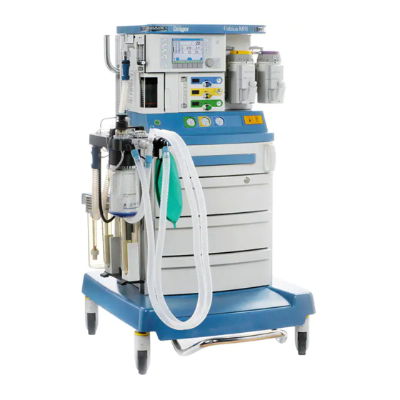
- Page 1 Instructions for Use Fabius MRI Anesthesia Workstation WARNING To properly use this medical device, Software 3.n read and comply with these Instruc- tions for Use.
-
Page 2: Working With These Instructions For Use
– »Restore Site Defaults« – Dashes indicate the listing of data, options or objects. Instructions for Use Fabius MRI SW 3.n Right-Hand Column - the Illustrations The illustrations provide visual reference for the text and for locating the various parts of the equip- ment. -
Page 3: Trademarks
This document is provided for customer information only, and will not be updated or exchanged without customer request. Depending on the configuration of the individual medical device, the images in the Instructions for Use may differ. Instructions for Use Fabius MRI SW 3.n... -
Page 4: Magnetic Resonance (Mr) Definitions
MR enviroment with specified conditions of use. Field conditions that define the specified MR enviroment include field strength, spatial gradient, dB/dt (time rate of change of the magnetic field), radio frequency (RF) fields and specific absorption rate (SAR). Instructions for Use Fabius MRI SW 3.n... -
Page 5: Table Of Contents
Symbol Definition ......33 Positioning the Fabius MRI at MRT System . . . 76 Connecting AC Power ....78 Operation Concept . - Page 6 Reprocessing Breathing system... . 174 Care List for Fabius MRI Components ..176 Reassembling the Breathing System ..178 Reinstalling the Ventilator .
-
Page 7: For Your Safety And That Of Your Patients
General WARNINGS and CAUTIONS ..10 Note on EMC/ESD risk for the device function Accessories in sterile packaging ... 10 Instructions for Use Fabius MRI SW 3.n... -
Page 8: Strictly Follow These Instructions For Use
Follow associated Assembly Instructions and strongly recommended that only these acces- Instructions for Use. sories be used in conjunction with the specific medical device. Otherwise the correct func- tioning of the medical device may be compro- mised. Instructions for Use Fabius MRI SW 3.n... -
Page 9: Patient Safety
The responsibility for the selection of the best level of patient monitoring lies solely with the medical device operator. Instructions for Use Fabius MRI SW 3.n... -
Page 10: General Warnings And Cautions
IEC 60601-1-2 value which exceeds the permissible value, do Electromedical devices are subject to special pre- not use the auxiliary outlets of the Fabius MRI: cautionary measures concerning electromagnetic use a separate wall socket. compatibility (EMC) and must be installed and put... - Page 11 Any person involved with the setup, opera- analyzer, pressure monitor, volume monitor, tion, or maintenance of the Fabius MRI anes- and end-tidal CO monitor in the breathing cir- thesia workstation must be thoroughly cuit at all times.
- Page 12 Make sure the external equipment is hospital- require that any use of ferromagnetic tools is grade grounded (regarding national regula- done only while the Fabius MRI is out of the tions) before connecting the equipment. scanner room. Disconnect the power supply from the electri- cal outlet before cleaning or servicing.
- Page 13 Risk of injury and image artifacts mains with protective earth. The Fabius MRI is designed for use in MR envi- ronment only as a system. The user should not WARNING assume that individual components of the system Use only non-rebreathing systems having a can be safely used in MR environment.
- Page 14 60 Hz supplies in the USA. The corresponding power cable is listed in the list of accessories. Connection of Fabius MRI to a 240 V / 60 Hz sup- ply is only allowed if it is a center-tapped-single- phase circuit and the power cable is a certified, hospital-grade cable 10 A/ 250 V AC of max.
-
Page 15: Intended Use
MEDIBUS and Vitalink Protocols ... 16 Restriction of Distribution ....16 Instructions for Use Fabius MRI SW 3.n... -
Page 16: Intended Use
Intended Use Indications for Use Fabius MRI is an inhalation anesthesia machine for The Fabius MRI is indicated as a continuous flow use in MRI environments in operating, induction anesthesia system useable in an MRI environment. and recovery rooms. It can only be used in MRI The Fabius MRI may be used for manually assisted scanner rooms with magnets 1.5 tesla and 3 tesla... -
Page 17: System Overview
Abbreviations ......32 Symbol Definition ..... 33 Instructions for Use Fabius MRI SW 3.n... -
Page 18: Front View
4 Interlock or Auto Exclusion Vapor mount 5 Additional alarm indicators 6 Fresh gas controls 7 Gauges (Pin-Index cylinders) 8 Writing table 9 Storage drawers 10 Central brake 11 Absorber 12 Compact Breathing System (COSY) Instructions for Use Fabius MRI SW 3.n... -
Page 19: Compact Breathing System (Top View)
9 Fresh gas decoupling valve 10 APL Bypass valve connection port 11 Breathing system mount with locking bolt 12 Selecting knob for »MAN« and »SPONT« on pressure limiting (APL) valve 13 Sample gas return port Instructions for Use Fabius MRI SW 3.n... -
Page 20: Rear View (Pin-Index Connector)
10 Pin-Index system 2 Sealed connector 11 Potential equalization pin 3 Type plate 12 Auxiliary power outlets 4 Ventilator hose connection 5 Interface panel 6 ON/OFF switch 7 Fuse 8 Compact Breathing System (COSY) Instructions for Use Fabius MRI SW 3.n... -
Page 21: Interface Panel
System Overview Interface Panel 1 COM 1 (for Service or fiber optic cable (8608376) only) 2 Oxygen Sensor 3 Volume Sensor 4 ON/OFF switch 5 APL 6 Fuse 7 Breathing Pressure 8 PEEP Instructions for Use Fabius MRI SW 3.n... -
Page 22: Vaporizers (Optional)
It has a selector lever used to select which vaporizer is enabled. Moving the selector lever away from the desired vaporizer allows that vaporizer to be used and the other to be locked out of use. Instructions for Use Fabius MRI SW 3.n... -
Page 23: Dräger Auto Exclusion 2-Vaporizer Mount
(opened), the interlock mechanism within that vaporizer’s mounting system is activated automati- cally, preventing the other vaporizer from being used. NOTE Only Dräger vaporizers labeled as “AUTO EXCLUSION” vaporizers are compatible with the Dräger Auto Exclusion 2-Vaporizer Mount. Instructions for Use Fabius MRI SW 3.n... -
Page 24: Auxiliary Oxygen Flowmeter
Only then the oxygen flow is completely off. WARNING Risk of fire Before cauterizing, close the flowmeter, remove the mask and wait a few moments to ensure that any oxygen accumulation has dis- sipated. ASTM F1850-22(2005) §76 Instructions for Use Fabius MRI SW 3.n... -
Page 25: O 2 Flush Button
When actuated, the valve delivers an unmetered flow of at least 35 L/min to the breathing system and breathing bag while bypassing the ventilator. The Fabius MRI does not need to be switched on in order to use the flush. -
Page 26: Apl Valve
APL valve knob increases the pressure threshold, and counterclockwise rotation of the APL valve knob decreases the pressure thresh- old. Lifting the top of the APL valve knob will temporarily relieve pressure. Instructions for Use Fabius MRI SW 3.n... -
Page 27: Writing Table
MR safe or MR conditional are removed from the writing table at MRT room. CAUTION For use, pull out the writing table until it engages. For parking position, push the table back until it engages. Instructions for Use Fabius MRI SW 3.n... -
Page 28: Communication Port
System Overview Communication Port 2 The Fabius MRI has one port on the back. It is labeled as COM 1. The use of COM1 for MEDIBUS communica- tion with an external device in the MRI envi- ronment has to be certified by Dräger. -
Page 29: Teslameter
System Overview Teslameter To ensure that the Fabius MRI works safely and without interference in the proximity of an MRT sys- tem, and that the MRT’s imaging is not influenced out of margin, there is defined distance that the Fabius MRI machine must maintain from the MRT system. -
Page 30: Accessory Mounting
System Overview Accessory Mounting The following figure shows the permitted mounting locations for accessories available for the Fabius MRI. Top shelf Instructions for Use Fabius MRI SW 3.n... -
Page 31: Maximum Weight Loads
MR scanning room and on a Fabius MRI anesthesia system. Objects placed on this machine that are not designed for use with this anesthesia system... -
Page 32: Abbreviations
Insp Flow Inspiratory flow Trigger Trigger Level L/min Liters per minute Uninterruptable power supply Manual ventilation Vacuum (e.g. for secretion suction) Expiratory minute volume mbar Millibar Tidal volume MEAN Mean pressure Magnetic resonance Instructions for Use Fabius MRI SW 3.n... -
Page 33: Symbol Definition
MR environment with specified conditions of use. The following symbols are used on other locations Distance to MRT magnetic of the Fabius MRI to provice quick and easy recog- strength ≤40 mtesla (400 gauss) nition of product functions. Oxygen Concentration Sensor... - Page 34 Transportation label,see page 114 absorbent bypass * as of SW 3.20 Vaporizer plug-in system -Flush The following symbols are used on the Fabius MRI monitoring user interface. Upper and Lower Alarm Limits Return to Home Screen Suppress Alarm Tone for Two Min-...
- Page 35 MRI room always lock the casters by pressing the Central Brake Lever ! CAUTION: After positioning in the MRI room always lock the casters by pressing the Central Brake Lever ! Instructions for Use Fabius MRI SW 3.n...
- Page 36 This page intentionally left blank Instructions for Use Fabius MRI SW 3.n...
-
Page 37: Operation Concept
Gas System Color Coding ....48 Screen Color Concept ....48 Instructions for Use Fabius MRI SW 3.n... -
Page 38: Control Panel
Operation Concept Control Panel The control panel on the Fabius MRI is character- ized by a small number of elements, clear layout, and ease of operation. Its main elements are: 1 A screen displaying all monitoring and ventila- tion information in numeric and graphic form 2 Fixed-function (“hard”) keys beside the screen... -
Page 39: The Screen Display
4 Respiratory volume monitoring window which displays the patient’s respiratory rate in breaths per minute (Freq), tidal volume (V ), minute vol- ume (MV), and the minute volume high and low alarm limits Instructions for Use Fabius MRI SW 3.n... -
Page 40: Rotary Knob
SIMV/PS ventilation mode (optional). 4 The »Pressure Support« key is used to select the Pressure Support ventilation mode (optional). 5 The »Pressure Control« key is used to select the Pressure Control ventilation mode. Instructions for Use Fabius MRI SW 3.n... -
Page 41: Soft Keys
NOTE The »Volume Alarms On/Off« soft key label does not appear in ManSpont mode because it is select- able on the ManSpont screen. See “Configuration during Operation” on page 152 for complete information. Instructions for Use Fabius MRI SW 3.n... -
Page 42: Selecting/Setting Monitoring Functions
»Default Settings« or »Configuration« label. Select and confirm the »Default Settings« label. The Default Settings column is selected. (Selecting and confirming the return arrow will exit the Default Settings column and redisplay the main Setup screen.) Instructions for Use Fabius MRI SW 3.n... - Page 43 (For example in the illustration on the right, the alarm limit was changed from 20 to 25.) Confirm the new value for the alarm limit. The new alarm limit is saved and cursor moves to the return arrow. Instructions for Use Fabius MRI SW 3.n...
-
Page 44: Selecting/Setting Ventilation Parameters
10 seconds. If the new set- ting is not confirmed within the timeout period, the current ventilation setting remains in effect and the Ventilation Settings window returns to the Wave- form window. Instructions for Use Fabius MRI SW 3.n... -
Page 45: Fresh Gas Control
O central supply pressure gauge 9 AIR central supply pressure gauge 10 O central supply pressure gauge 11 O cylinder pressure gauge* Only used with Pin-Index connectors (not present with threaded connectors). Instructions for Use Fabius MRI SW 3.n... -
Page 46: Total Flow Meter
2 L/min. If 1 L/min of N O is needed, open the N O flow con- trol knob until the total flow meter reads 3 L/min: 2 L/min O plus 1 L/min N Instructions for Use Fabius MRI SW 3.n... -
Page 47: Fresh Gas Flow Monitoring Resolution
Operation Concept Fresh Gas Flow Monitoring Resolution The Fabius MRI can be configured by DrägerService or your local authorized service organization to display fresh gas flow rates either in a standard resolution mode or in a high resolution mode: 1 If standard resolution is configured, the elec- tronic fresh gas flow indicators support 100 mL/min increments (format xx.x L/min), and... -
Page 48: Led Indicators
Gas System Color Coding Each connection, valve, gauge, and flow meter on the Fabius MRI is color-coded for the appropriate gas, as shown the table below: Yellow Black/White... -
Page 49: Assembly
Bag ....... . . 56 Positioning the Fabius MRI at MRT System 76... -
Page 50: Activating The Battery
MRI scanner is adversely affected by the vaporizer and the anesthesia workstation. Activating the Battery The Fabius MRI anesthesia machine is shipped with the battery fuse disconnected in order to pre- vent discharge during shipment and storage prior to installation. -
Page 51: Fitting The Co Absorber On The Compact Breathing System
Such dust and particles can cause leaks in the system. 1 Fit the absorber canister into position below the breathing system and turn it counterclockwise as far as possible. Instructions for Use Fabius MRI SW 3.n... -
Page 52: Inserting The Flow Sensor
Release the locking bolt and rotate the compact breathing system until the locking bolt locks into position. For information on filling and installing the reusable absorber, see page 189. Instructions for Use Fabius MRI SW 3.n... - Page 53 2 Connect the ventilation hose to the ventilator 3 attach it to the conical connector ventilator port on the compact breathing system. If the Fabius MRI is equipped with a threaded con- nector, the sealing rings on the threaded connector must be undamaged and clean.
-
Page 54: Installing The Drägersorb Clic Adapter
– CLIC Absorber Free, or – Infinity ID CLIC Absorber 800+, or – Infinity ID CLIC Absorber Free can be used on the Fabius MRI by using the Drägersorb CLIC adapter. For information on installing the Drägersorb CLIC adapter, consult its Instructions for Use. -
Page 55: Connecting The Waste Gas Outlet Port
Assembly Connecting the Waste Gas Outlet Port Screw the waste gas port into the compact breathing system from underneath. Instructions for Use Fabius MRI SW 3.n... -
Page 56: Installing The Breathing Bag
This arm would be attracted to the MRT sys- tem which would create a risk of injury. WARNING Risk of use of toxic or incompatible materials Breathing bags used on the Fabius MRI must comply with current national standards. CAUTION Risk of unintended perioperative awareness Make sure that during ventilation the bag is tightly connected to the bag arm. -
Page 57: Connecting Pipeline Supply Of N 2 O, Air And O 2
O (1), AIR (2), and (3) are standard. These gauges are located directly to the right of their corresponding flow con- trol valves. A typical pressure gauge and flowmeter assembly is shown in the figure. Instructions for Use Fabius MRI SW 3.n... -
Page 58: Connecting The Reserve Gas Cylinders For N 2 O, Air And O 2 ( For Pin-Index Mounting)
O, AIR and O ( for Pin-Index Mounting) WARNING Use only non-magnetic (e.g., aluminum) cylin- ders with the Fabius MRI. Steel cylinders will cause serious injury or death if brought into an MR scanning room. WARNING When attaching a cylinder, ensure that only one washer is installed between the cylinder and the yoke gas inlet. - Page 59 Tighten the yoke firmly. When required, the cylinder valve (8) is opened using the cylinder wrench (9) that is provided. When a cylinder is removed, place the yoke plug (10) in the yoke assembly and tighten. Instructions for Use Fabius MRI SW 3.n...
-
Page 60: Dimensions Of Usable Cylinders
Diameter 4.3 in (111 mm) D-size Pin-Index Cylinder (without valve) 4.0 L Height 25.5 in (654 mm) Diameter 4.3 in (111 mm) 2.8 L Height 16.5 in (419 mm) Diameter 4.3 in (111 mm) Instructions for Use Fabius MRI SW 3.n... -
Page 61: Connecting The Agss Anesthetic Gas Scavenging System
Assembly Connecting the AGSS Anesthetic Gas Scavenging System* Every Anesthetic Gas Scavenging System (AGSS) used on the Fabius MRI must follow ISO standard 8835-3. The scavenging system is used with vacuum waste-gas disposal systems. The AGS or passive scavenger is not applied as an independent system. - Page 62 Otherwise there may be a shor- tage of fresh-gas in the breathing system. For detailed information on the AGS, refer to the specific Instructions for Use provided with the anes- thetic gas receiving system AGS (9038579). Instructions for Use Fabius MRI SW 3.n...
-
Page 63: Connecting The Passive Scavenger
Connect the other end of the hose to the hospi- tal waste gas disposal system. For detailed information on the passive scavenger system, refer to separate Instructions for Use. optional Instructions for Use Fabius MRI SW 3.n... -
Page 64: Connecting The Suction System
Assembly Connecting the Suction System* The optional suction system for the Fabius MRI consists of a suction regulator and a suction bottle system. The suction regulator is attached to a holder, which is fastened on the side channel on the anesthesia device. -
Page 65: Connecting The Breathing Hoses And Breathing Bag
Before each use, check the breathing hoses for damage. WARNING Risk of use of toxic or incompatible materials Breathing hoses used on the Fabius MRI must comply with current national standards. WARNING Do not use antistatic or conductive breathing hoses or masks. There is a risk of burns in the MRI environment or when using high fre- quency electrosurgical equipment. - Page 66 2 Connect both patient breathing hoses to the Y-piece. 3 Connect the breathing bag to the bag fitting on the breathing system. WARNING Risk of strangulation Use caution when connecting the patient. Instructions for Use Fabius MRI SW 3.n...
-
Page 67: Instructions For Use Of Bacterial Filters, Endotra
When using coaxial hoses, leaks between the inner and outer hoses cannot be detected during the self- test/leak test. Instructions for Use Fabius MRI SW 3.n... -
Page 68: Inserting A New O 2 Sensor Capsule
3 Push the O sensor into the port opening of the inspiratory port dome, and 4 Plug the connector into the fitting labeled on the connector panel on the back of the machine. Instructions for Use Fabius MRI SW 3.n... -
Page 69: Connecting The Pressure Sensor
(3), the breathing pressure gauge port (4) to the pressure gauge connector, and then to the bacterial filter and onto the port labeled on the connector panel on the back of the machine (5). optional Instructions for Use Fabius MRI SW 3.n... -
Page 70: Connecting The Flow Sensor
4 Plug the control hose to the connection port on the APL Bypass valve and to the connection port marked APL on the connection panel. NOTE The APL bypass hose is larger than the PEEP/P hose. Instructions for Use Fabius MRI SW 3.n... -
Page 71: Preparing The Ventilator
1 Close the ventilator door with the attached ven- tilator unit. Ventilator Safety Features – High pressure safety relief valve (A). – Negative pressure safety relief valve (B). – Ventilator chamber pressure sensor. Instructions for Use Fabius MRI SW 3.n... -
Page 72: Installing Vaporizers
Installing Vaporizers Install vaporizers as directed in the appropriate Instructions for Use supplied with the vaporizers available for use with the Fabius MRI. The anesthetic vaporizer used with the anesthesia workstation shall comply with ISO 8835-4. The anesthesia workstation must be used with anesthetic gas monitoring complying with ISO 21647, if an anesthetic vaporizer is used. - Page 73 Only Vapor 2000 vaporizers can by used on the Fabius MRI in MRT scanner rooms. CAUTION Risk of injury Dräger metal keyed filler adapters and Dräger fill adapters are labeled with “MRI” are not ferromag- netic. Instructions for Use Fabius MRI SW 3.n...
-
Page 74: Connecting Auxiliary Equipment
WARNING Risk of tip-over and personal injury If monitors and other equipment are placed on top of the Fabius MRI, the risk of tipping over the unit is increased, especially when rolling over thresholds etc. Remove all monitors and other equipment from the top of the Fabius MRI before moving the unit. -
Page 75: Auxiliary Power Outlets
Risk of increased leakage current Do not connect HF surgical devices to the auxiliary power outlets. WARNING Risk of increased leakage current Additional power adapter outlets must not be connected to the auxiliary power outlets. Instructions for Use Fabius MRI SW 3.n... -
Page 76: Positioning The Fabius Mri At Mrt System
Preparation Before first use of the Fabius MRI in the MRT room, perform steps as follows: Define the 40 mtesla field strength distribution in Z and X direction by using an external Tesla meter. -
Page 77: Positioning
CAUTION Make sure that the additional alarm lights at the edges of the top shelf of the Fabius MRI are always visible. Following the setup and positioning of the Fabius MRI, perform the imaging test protocol pro- vided in Appendix 2 of this manual. -
Page 78: Connecting Ac Power
60 Hz supplies in the USA. The corresponding power cable is listed in the list of accessories. Connection of Fabius MRI to a 240 V / 60 Hz sup- ply is only allowed if it is a center-tapped-single- phase circuit and the power cable is a certified, hospital-grade cable 10 A/ 250 V AC of max. -
Page 79: Checklist
Connect AC power – connect muffler to waste gas port of COSY – connect auxiliary devices – connect Fabius MRI to mains power Fill and install the absorber or install the optional Drägersorb CLIC Adapter Check teslameter Install the breathing bag extension arm to... -
Page 80: Daily And Pre-Use Checkout
Assembly Daily and Pre-use Checkout At the completion of the assembly of the Fabius MRI, perform the Daily and Pre-use Check- out procedure provided in the Appendix 1 of this manual to ensure that the machine is ready for operation. -
Page 81: Getting Started
Powering-Up the Machine ....82 Power-Up Standby Screen ....83 Checking Readiness for Operation ..83 Instructions for Use Fabius MRI SW 3.n... -
Page 82: Powering-Up The Machine
After a brief delay, the Standby screen appears. CONDITIONALLY FUNCTIONAL A noncritical fault was detected. The Fabius MRI may be used, but call DrägerService or your local authorized service organization. Press the rotary knob to continue operation. -
Page 83: Power-Up Standby Screen
WARNING The power-on self-test should be carried out once a day. Switch Fabius MRI off and on or start the self- test by pressing the soft key »Run System Test«. Power-Up Standby Screen Following a successful power-up, the Standby screen appears and provides instructions on start- ing the operation of the Fabius MRI. - Page 84 This page intentionally left blank Instructions for Use Fabius MRI SW 3.n...
-
Page 85: Operation
End of Vaporizer Use ....113 When Fabius MRI is not in use ... 113 Preparing for Storage or Transport . -
Page 86: Power-Up Standby Screen
Power-Up Standby Screen Following a successful power-up, the Standby screen appears and provides instructions on start- ing the operation of the Fabius MRI. Setting Fresh Gas Flow Set the fresh gas flow to the desired concentration using the flow control knobs on the front of the machine. - Page 87 A vaporizer must never be left switched on without a fresh-gas flow, because high-concentration anesthetic vapor may leak into machine lines and ambi- ent air, causing damage to materials and health risks. Instructions for Use Fabius MRI SW 3.n...
-
Page 88: Setting Vaporizer Concentration
2 Press the button and turn the handwheel coun- terclockwise to set the required anesthetic gas concentration. Regularly check the filling level on the sight glass. When reaching the minimum mark, fill the vaporizer with anesthetic agent. Instructions for Use Fabius MRI SW 3.n... -
Page 89: O 2 Flush
When actuated, the valve delivers an unmetered flow of at least 35 L/min to the breathing system and breathing bag while bypassing the ventilator. The Fabius MRI does not need to be switched on in order to use the O flush. -
Page 90: Low Flow Anesthesia
Drägersorb 800 Plus or Drägersorb FREE. The color change indicates that the CO absorbent can no longer absorb CO (Drägersorb 800 Plus and Drägersorb FREE change from white to violet). Instructions for Use Fabius MRI SW 3.n... - Page 91 – Powdered soda lime on the skin must be washed off immediately, because it may irri- tate the skin. NOTE Please refer to the specific Instructions for Use for "Drägersorb 800 Plus or Drägersorb FREE". Instructions for Use Fabius MRI SW 3.n...
- Page 92 1 Fit the absorber canister into position below the breathing system and turn it counterclockwise as far as possible. CAUTION Risk of unintended perioperative awareness Make sure that during ventilation the absorber canister is tightly connected to the COSY. Instructions for Use Fabius MRI SW 3.n...
-
Page 93: Clic Adapter (Optional)
Operation CLIC Adapter (Optional) The disposable CLIC adapter absorber can also be used on the Fabius MRI. For information on install- ing the CLIC adapter, consult its Instructions for Use. Points to note when using the CLIC adapter with neonates and infants The compliance of the breathing system is reduced when the disposable absorber is removed. -
Page 94: Ventilation
It remains blinking until the selected mode of operation is confirmed. 2 The Waveform window is replaced by the ManSpont window and a message that pro- vides instructions to confirm the mode change. Instructions for Use Fabius MRI SW 3.n... - Page 95 30 seconds, and for warning alarms from 30 seconds to 60 seconds. Rotate the APL valve adjustment knob to the desired pressure. Clockwise rotation increases the pressure, and counterclockwise rotation decreases the pressure. Instructions for Use Fabius MRI SW 3.n...
- Page 96 Start manual ventilation. The pressure will be limited to the value set on the APL valve. Start manual ventilation by hand via the breath- ing bag. To temporarily relieve pressure: Pull up on the APL valve knob. Instructions for Use Fabius MRI SW 3.n...
-
Page 97: Volume Control Ventilation
When the ventilator settings for Volume Control cause the ventilator to operate at its limits of per- formance, it is not possible for the Fabius MRI to apply compliance compensation. If the ventilator's performance limit is reached, it is not possible to... - Page 98 20 to 1400 [mL] Frequency 4 to 60 Freq [bpm] ([1/min]) Insp time: 4:1 to 1:4 Exp time Insp pause time: 0 to 50 Insp time PEEP [cmH O] ([hPa]) 0 to 20 Instructions for Use Fabius MRI SW 3.n...
- Page 99 (disconnection) and continuous pressure. An alarm is generated when the pressure curve does not cross the pres- sure threshold either from above or below. Instructions for Use Fabius MRI SW 3.n...
-
Page 100: Pressure Control Ventilation
Pressure Control Mode. Frequency 4 to 60 Freq [bpm] ([1/min]) Insp time: 4:1 to 1:4 Exp time Inspiratory Flow 10 to 75 Insp Flow [L/min] PEEP [cmH O] ([hPa]) 0 to 20 Instructions for Use Fabius MRI SW 3.n... - Page 101 Flow Freq sure monitoring to detect apneas (disconnection) and continuous pressure. An alarm is generated when the pressure curve does not cross the pres- sure threshold either from above or below. Time Instructions for Use Fabius MRI SW 3.n...
-
Page 102: Pressure Support Ventilation
It is not intended as a primary mode of ventilation. When delivering Apnea Ventilation, the Fabius MRI Δ uses the Pressure Support settings for Freq Min, Insp Flow, and PEEP. - Page 103 After the mode change is confirmed, the »Pressure Support« key LED switches from blinking to constantly on, the ventilator switches to the Pressure Support mode, and the wave- form is restored. Instructions for Use Fabius MRI SW 3.n...
- Page 104 (disconnection) and continuous pressure. An alarm is generated when the pressure curve does not cross the pres- sure threshold either from above or below. Instructions for Use Fabius MRI SW 3.n...
-
Page 105: Simv/Ps Ventilation
If the ventilator settings are not correct, for each parameter that needs to change, press the cor- responding soft key, select the correct value, and confirm the change. When the parameter changes are completed, confirm the ventilation mode change. Instructions for Use Fabius MRI SW 3.n... - Page 106 O] ([hPa]) 0 to 20 Trigger Sensitivity 2 to 15 Trigger [L/min] Inspiratory Flow 10 to 85 Insp Flow [L/min] SIMV insp. time 0.3 to 4.0 [seconds] INSP Insp pause time: 0 to 50 Insp time Instructions for Use Fabius MRI SW 3.n...
- Page 107 (disconnection) and continuous pressure. An alarm is generated when the pressure curve does not cross the pres- sure threshold either from above or below. Instructions for Use Fabius MRI SW 3.n...
-
Page 108: When Changing Between Ventilation Modes
Pressure Control. When changing from Volume Control or Pressure Control to Pressure Support, the suggested value for Insp Flow is either the last used value or the site default value. Instructions for Use Fabius MRI SW 3.n... - Page 109 Insp Flow settings shall automatically be transferred from SIMV/PS to Pressure Support. When switching from SIMV/PS mode to Pressure Support mode, the Trigger and PEEP settings shall automatically be transferred from SIMV/PS to Pres- sure Support. Instructions for Use Fabius MRI SW 3.n...
-
Page 110: Ventilator Safety Features
NOTE The user should then take action to resolve this, for example by increasing the fresh gas flow. Fabius MRI behavior in case of no action taken by the user – breathing bag gradually empties completely – after two more strokes the alarm »FRESH GAS LOW«... -
Page 111: Changing Patients
Operation Changing Patients WARNING Risk of inappropriate alarm settings As it is possible that Fabius MRI devices within in a care area have different site default alarm limit configurations, check whether the pre-set alarm limits are appropriate to the new patient. -
Page 112: Ending Operation
2 Turn vaporizers off by turning the handwheel to »0« until the button engages. Turn off fresh gas flow on the Fabius MRI. Sleep mode will activate 2.5 minutes after fresh gas is turned off. Close the cylinder valves. -
Page 113: End Of Vaporizer Use
When Fabius MRI is not in use If Fabius MRI is not used for an extended period: Unplug the medical gas hoses from the wall supply points of the central gas supply. -
Page 114: Preparing For Storage Or Transport
WARNING All the procedures described in this manual require that any use of ferromagnetic tools can only be done while the Fabius MRI is out of the scanner room. WARNING Do not bring any ferromagnetic tools or equip- ment into the scanning room. - Page 115 This precau- tion prolongs the service life of the sensor. 2 Switch off system power using the switch on the back of the machine, and disconnect the power plug. Disconnect the scavenger hoses. Instructions for Use Fabius MRI SW 3.n...
-
Page 116: Moving The Machine
CAUTION Watch hoses connected to the patient while mov- ing the Fabius MRI. CAUTION Do not push or pull the Fabius MRI using the absorber system, vaporizers, ventilator, or moni- tor. CAUTION The Fabius MRI should be moved by people who can handle its weight (approximately 425 lb (192.8 kg)). -
Page 117: Monitoring
Limits ....... 129 Instructions for Use Fabius MRI SW 3.n... -
Page 118: Main Screen
The Fabius MRI main screen displays current alarms, oxygen monitoring, breathing pressure monitoring, and respiratory volume monitoring information. Alarms Fabius MRI alarms are organized into three cate- gories based on urgency: – Warning: highest priority alarm, requiring immediate response – Caution: medium priority alarm, requiring prompt action –... -
Page 119: Sorting Of Displayed Alarms
If an alarm with the category Caution is active and an alarm with the category Warning is generated, the alarm sequence is started for the warning because the warning is assigned the highest prior- ity. Instructions for Use Fabius MRI SW 3.n... -
Page 120: Silencing Alarms
1 Press the »Silence« key, the yellow LED turns off. Disabling Volume Alarms Visual and audible volume alarms can be turned on or off during operation using the »Setup« key. See “Volume Alarms On/Off” on page 153. Instructions for Use Fabius MRI SW 3.n... -
Page 121: Setting Alarm Limits
Confirm the new value for the alarm limit. The new alarm limit is saved and the cursor moves to the return arrow. The adjustment range and factory default values for all alarms on the Fabius MRI are shown in the fol- lowing table. Alarm Adjustment... -
Page 122: Oxygen Monitoring
2 high oxygen concentration alarm limit 3 low oxygen concentration alarm limit Setting Oxygen Monitoring Alarm Limits Follow the procedure "Setting Alarm Limits" on page 121 to change the high or low alarm limit. Instructions for Use Fabius MRI SW 3.n... -
Page 123: Calibrating The Oxygen Sensor
1 Press the »Setup« key on the front panel. The Setup window appears at the bottom of the screen. 2 Press the »Calibrate O2 Sensor« soft key. 3 The calibration instruction window replaces the Setup window. Follow the directions provided. Instructions for Use Fabius MRI SW 3.n... - Page 124 »O2 SENSOR FAIL!« appears in the Alarm window. If this happens, ensure that the sensor is correctly assembled and recalibrate the oxygen sensor. Instructions for Use Fabius MRI SW 3.n...
-
Page 125: Consequences Of Incorrect O 2 Calibration
Fabius MRI will not complete an attempted calibration; however, if the calibration gas is rich or lean but is within certain limits, the Fabius MRI will complete the calibration. As a result, when display- ing sensor measurements, the Fabius MRI displays an oxygen percentage either higher or lower than the actual oxygen percentage. -
Page 126: Respiratory Volume Monitoring
99.9 L/min. 4 Minute Volume Alarm High Limit indicates the volume above which an alarm condition occurs (L/min). 5 Minute Volume Alarm Low Limit indicates the volume below which an alarm condition occurs (L/min). Instructions for Use Fabius MRI SW 3.n... -
Page 127: Volume Monitoring Alarms
While the ventilator is off and the system is in Man- Spont mode, these alarms are generated at 30 seconds (Caution) and 60 seconds (Warning). The Fabius MRI's volume alarms are automatically enabled when the ventilator is switched from Standby to a ventilation mode. -
Page 128: Breathing Pressure Monitoring
The breathing pressure monitoring windows show the following breathing pressure information in numeric and graphic form: NOTE The Fabius MRI can be configured by DrägerService or your local authorized service organization to display mean pressure (MEAN) instead of plateau pressure (PLAT). -
Page 129: Breathing Pressure Monitoring Alarms
121 to change the breathing pressure high or threshold alarm limit. NOTE The pressure threshold alarm limit should be as close as possible to the sensed plateau pressure without exceeding it, approximately 4 cmH (hPa) below the plateau pressure. Instructions for Use Fabius MRI SW 3.n... - Page 130 This page intentionally left blank Instructions for Use Fabius MRI SW 3.n...
-
Page 131: Configuration
Access Alarm Log ..... 156 Access Alarm Volume ....156 Instructions for Use Fabius MRI SW 3.n... -
Page 132: Configuration Functions In Standby Mode
Standby screen: – »Run System Test« – »Calibrate Flow Sensor« – »Calibrate O2 Sensor« – »Leak / Compl Test« – »Access Alarm Log« – »Restore Site Defaults« Turn off fresh gas flow. Instructions for Use Fabius MRI SW 3.n... -
Page 133: Sleep Mode
86). Pressing this key restores the site defaults. The test results are posted on the screen. Following successful completion, the system returns to the Standby screen. This System Test checks the functionality of the electronics of the system. Instructions for Use Fabius MRI SW 3.n... -
Page 134: Calibrate Flow Sensor
»Flow Calibration Failed«. Troubleshooting Flow Calibration Failure If the flow sensor cannot be calibrated, retry the cal- ibration. If the flow sensor still cannot be calibrated, call DrägerService or your local authorized service organization. Instructions for Use Fabius MRI SW 3.n... -
Page 135: Calibrate O 2 Sensor
If the O sensor cannot be calibrated, replace the capsule in the O sensor housing (see page 189). If the O sensor still cannot be calibrated, call DrägerService or your local authorized service organization. Instructions for Use Fabius MRI SW 3.n... -
Page 136: Leak/Compliance Test
– Press O flush button, build up a pressure of 15 to 30. Upon completion of the test, the results are posted on the screen. Press the rotary knob to return to the Standby screen. Instructions for Use Fabius MRI SW 3.n... - Page 137 Displayed result Setting [mL/min] [mL/min] Fresh-Gas Ventilator Decoupling PEEP ≤250 measured value and PASSED Vaporizer Bypass Valve 251 to 350 measured value and Absorber FAILED Flow Tube >350 >350 and FAILED Oxygen Scavenging Flush Instructions for Use Fabius MRI SW 3.n...
- Page 138 – absorber canister not firmly mounted in place – flow sensor not installed properly – breathing system not assembled and installed correctly – microbial filters not connected securely – breathing bag arm not tight or defective Instructions for Use Fabius MRI SW 3.n...
-
Page 139: Access Alarm Log
To exit the alarm log and return to the Standby screen, select and confirm the return arrow. CAUTION Alarm log data is deleted if Fabius MRI is swit- ched off or a total loss of electrical power supply occurs. Restore Site Defaults 2 Press the »Restore Site Defaults«... -
Page 140: Standby Setup Screen
»Default Settings« (see below) or »Configuration« (see page 147). (Selecting and confirming the return arrow on the right of the Setup screen will exit the Standby Setup screen and redisplay the Standby screen.) Instructions for Use Fabius MRI SW 3.n... -
Page 141: Default Settings In Standby Setup
– »Alarm Volume« – »Restore Factory Defaults« Volume Settings Select and confirm the »Volume Settings« label on the Standby Setup screen. The Default Volume Settings window appears at the bottom of the screen. Instructions for Use Fabius MRI SW 3.n... - Page 142 Pressure Settings, Pressure Support Settings, and SIMV/PS Settings Use the procedure described in “Volume Settings” to change the parameters associated with these ventilator modes. Instructions for Use Fabius MRI SW 3.n...
- Page 143 Confirm the new value for the O alarm limit. The new alarm limit is saved and cursor moves to the return arrow. If necessary, repeat the process for the other parameter alarm limits. Instructions for Use Fabius MRI SW 3.n...
- Page 144 Configuration The adjustment range and factory default values for all alarms on the Fabius MRI are shown in the fol- lowing table. Alarm Adjustment Factory Parameter Range Default Value 19 to 100 18 to 99 0.1 to 20.0 12.0 L/min 0.0 to 19.9...
- Page 145 Select and confirm »Yes« or »No«. When »Yes« is selected, the factory defaults are restored and replace the current default set- tings. The factory defaults for the Fabius MRI are shown in the table below: Parameter Factory Default Settings Volume...
- Page 146 Low = 20 Settings for O Alarm High = 12.0 Default Low = 3.0 Settings for MV Alarm High = 40 Default Low = 8 Settings for Pressure Alarm Audio Volume level = 5 Volume Instructions for Use Fabius MRI SW 3.n...
-
Page 147: Configuration In Standby Setup
The following settings are available under Configu- ration: – »Time Set« – »Time Format« – »Date Set« – »Date Format« – »Acoustic Confirmation« – »Alarm Tone Sequence« – »Waveform Display« – »Display Background« Instructions for Use Fabius MRI SW 3.n... - Page 148 »15« to »30«). The new time values are saved, the Time Set win- dow is removed from the screen, and the cursor returns to the Time Set label. Instructions for Use Fabius MRI SW 3.n...
- Page 149 »Time Format« label. Date Set The values that can be selected are two-digit numerical values for day, month, and year. Use the procedure described in “Time Set” on page 148 to change the date parameter. Instructions for Use Fabius MRI SW 3.n...
- Page 150 Alarm Tone Sequence The values that can be selected for the alarm tone sequence are »Standard« or »Dräger«. Use the procedure described in “Time Format” on page 149 to change the alarm tone sequence parameter. Instructions for Use Fabius MRI SW 3.n...
- Page 151 Display Background The values that can be selected for the display background are »Dark« or »Light«. Use the procedure described in “Time Format” on page 149 to change the display background param- eter. Instructions for Use Fabius MRI SW 3.n...
-
Page 152: Configuration During Operation
Setup functions during operation. If no rotary knob activity occurs within 15 seconds, the Setup win- dow is removed and the waveform window is redis- played. The waveform window can be also be displayed by pressing the »Home« key. Instructions for Use Fabius MRI SW 3.n... -
Page 153: Volume Alarms On/Off
In the absence of a current plateau pressure data value, pressing the soft key will have no effect. NOTE In SIMV/PS mode, the breathing pressure thresh- old will be set relative to the mandatory ventilation stroke. Instructions for Use Fabius MRI SW 3.n... -
Page 154: Calibrate O 2 Sensor
Sensor and expose to room air for 2 minutes. – To start O Calibration press rotary knob. – Observe Calibration status in O data window. – Reinsert O Sensor after successful Calibra- tion. Instructions for Use Fabius MRI SW 3.n... -
Page 155: Des Comp On/Off
The Des Comp On/Off parameter remains in the Off position on the Fabius MRI. WARNING The Desflurane vaporizer is not useable in an MR environment. In an MR environment func- tionality of the Desflurane vaporizer will be compromised. Instructions for Use Fabius MRI SW 3.n... -
Page 156: Access Alarm Log
Select and confirm a new alarm volume value in the range of 1 (minimum) to 10 (maximum). The value is saved and the Alarm Volume Setting window is replaced by the Setup window. Instructions for Use Fabius MRI SW 3.n... -
Page 157: Fault-Cause-Remedy
Overriding the Ventilator ....160 Fault-Cause-Remedy ....162 Instructions for Use Fabius MRI SW 3.n... -
Page 158: Power Failure Backup
Fault-Cause-Remedy Power Failure Backup When AC power is interrupted from the Fabius MRI, the internal battery backup will provide full operation of the ventilator and internal monitors for up to two hours after the power interruption. The battery depletion rate depends upon ventilator set-... - Page 159 When the battery is completely discharged Fabius MRI switches off. As a consequence all indi- vidual settings, which are not saved in the default settings, will be lost.
-
Page 160: Ventilator Fail State
Fault-Cause-Remedy Ventilator Fail State If the Fabius MRI does not recover from a »VENTILATOR FAIL!!!« condition: Switch to ManSpont mode by pressing the ManSpont key and confirming the mode change by pressing the rotary knob. Set the APL valve to MAN position. - Page 161 If the diagnostic tests result in FUNCTIONAL, the Fabius MRI will automatically switch to ManSpont mode if a fresh-gas flow is detected. Fabius MRI respiratory monitoring is available. If the diagnostic tests result in NON-FUNCTIONAL, manual venti- lation is still possible but Fabius MRI respiratory monitoring is not available.
-
Page 162: Fault-Cause-Remedy
Fault-Cause-Remedy Fault-Cause-Remedy The Fabius MRI divides alarm messages into three categories based on priority. Exclamation marks indicate the priority. The alarm messages are dis- played on colored background if the option "Color display" is enabled: Warning (red) high priority Caution (yellow) - Page 163 Call DrägerService or your local authorized service orga- nization. EXP PRESSURE HIGH PEEP is more than 4 cmH Check PEEP/P , etc. hoses (hPa) above the PEEP setting for kinks. (16) in an automatic ventilation mode. Instructions for Use Fabius MRI SW 3.n...
- Page 164 Control, Pressure Sup- port, or SIMV/PS mode. MINUTE VOLUME HIGH Minute volume has exceeded Calibrate flow sensor. (14) upper alarm limit. Replace if necessary. Flow sensor has not been cali- brated. Sensor faulty. Instructions for Use Fabius MRI SW 3.n...
- Page 165 Connect mains. Facility power failure. PRES APNEA ALARM OFF Pressure alarms off in Man- Spont. PRESSURE LIMITING Measured pressure equals or Check ventilator and P Volume Control mode exceeds P ventilator settings. setting. Instructions for Use Fabius MRI SW 3.n...
- Page 166 Check diaphragm and close (28) rectly. cover. Check PEEP/P line for disconnect or leak. Select Standby Mode and switch back to the previous ventilation mode. VOLUME ALARMS OFF Volume alarms disabled by operator. Instructions for Use Fabius MRI SW 3.n...
-
Page 167: Cleaning
......175 Care List for Fabius MRI Components . . . 176 Reassembling the Breathing System . -
Page 168: Safety Information On Reprocessing
Affected parts: compact breathing system, valve cover, expiration nozzle, absorber and APL valve. Afterwards rinse all parts thoroughly under running water until no residue of the cleaning agents is detected (approx. 5 min). Instructions for Use Fabius MRI SW 3.n... -
Page 169: Manual Cleaning
Remove disinfectant residues. Observe the relevant Instructions for Use. Rinse parts under running water until no clea- ning agent residues are discernible. Check parts for visible soiling and damage. Repeat manual cleaning if necessary. Instructions for Use Fabius MRI SW 3.n... -
Page 170: Visual Inspection
CAUTION CAUTION Risk of damage to the medical device The surfaces of Fabius MRI, the pressure gas Even accessories designed to be reused (e.g. hoses and cables must not be treated with alcohol after reprocessing) have a limited service life. Due containing agents. -
Page 171: Removing The Compact Breathing System
5 Extract the gasket on top of the valve disc. Removing the Expiratory Valve 6 Unscrew the retaining nut. 7 Remove the inspection cap. 8 Extract the valve disc. 9 Remove the gasket on top of the valve disc. Instructions for Use Fabius MRI SW 3.n... -
Page 172: Removing The Waste Gas Port
Disinfect and clean the flow sensor as described in the Instructions for Use of the Spirolog, Infinity ID flow sensor and SpiroLife flow sensors. Instructions for Use Fabius MRI SW 3.n... -
Page 173: Removing Parts Of The Ventilator
1 Open the ventilator door. 2 Disconnect the pressure sensor line of the ven- tilator chamber from the respective connector. 3 Unlock the three clasps, 4 Remove the cover. 5 Remove the ventilator diaphragm. Instructions for Use Fabius MRI SW 3.n... -
Page 174: Removing Anesthetic Gas Scavenging System
Reprocessing/disinfection instructions for the in the valve plate can lead to impairment of reusable suction bottle and the suction regulator, device function or to failure of the medical refer to their respective Instructions for Use. device. Instructions for Use Fabius MRI SW 3.n... -
Page 175: O 2 Sensor
Infinity ID flow sensor must not be sterilized in Fabius MRI components page 176. Follow the hot steam. The flow sensor is not resistant to high hygiene regulations of the hospital! temperatures and will be destroyed. -
Page 176: Care List For Fabius Mri Components
The list is only intended as a rough guideline. The instructions of the hospital´s hygiene officer shall CAUTION prevail and must be observed! Fabius MRI and its components must not be trea- ted with formaldehyde vapors or ethylene oxide. Fabius MRI Recommen-... - Page 177 7) Remove any water which may have accumulated in the ventilator diaphragm. Large quantities of condensed water can negatively effect the operation of the device and lead to failure of the medical device! Instructions for Use Fabius MRI SW 3.n...
-
Page 178: Reassembling The Breathing System
Lines/cables caught underneath the APL valve adjustment knob could interfere with proper functioning of this valve. 10 Position the APL valve in the valve seat, and tighten securely with the retaining nut. Instructions for Use Fabius MRI SW 3.n... -
Page 179: Screw The Waste Gas Port
– breathing bag extension* and bag – flow sensor and breathing pressure cables – APL bypass and PEEP/P cables – O sensor cable – breathing system hoses Follow instructions on page 189 to reinstall the absorber system optional Instructions for Use Fabius MRI SW 3.n... -
Page 180: Reinstalling The Ventilator
4 Insert the diaphragm. Fit the cover and lock the three clasps. 5 Connect pressure sensor line of the ventilator chamber to the respecive connector. Close the ventilator door with the attached ven- tilator unit. Instructions for Use Fabius MRI SW 3.n... -
Page 181: Reinstalling The Scavenger System
Reinstalling the Scavenger System Reconnecting the Anesthetic Gas Receiving System (AGS) Every Anesthetic Gas Scavenging System (AGSS) used on the Fabius MRI must follow ISO standard 8835-3. The scavenging system is used with vacuum waste-gas disposal systems. The AGS or passive scavenger is not applied as an independent system. - Page 182 For detailed information on the AGS, refer to the specific Instructions for Use provided with the anesthetic gas receiving system AGS (9038579). For detailed information on the passive scaven- ger refer to the specific Instructions for Use. Instructions for Use Fabius MRI SW 3.n...
-
Page 183: Reinstalling The Suction System
Cleaning Reinstalling the Suction System Reconnecting the Suction System The optional aspiration system for the Fabius MRI consists of an suction regulator and a suction bottle. The suction regulator is attached to a holder, which is fastened on the side channel of the anes- thesia device. -
Page 184: Checking Readiness For Operation
Cleaning Checking Readiness for Operation At the completion of the reassembly of the Fabius MRI, perform the Daily and Preuse Check- out procedure provided in the Appendix of this manual to ensure that the machine is ready for operation. Instructions for Use Fabius MRI SW 3.n... -
Page 185: Maintenance
CLIC Adapter ......191 Checking Readiness for Operation ..191 Instructions for Use Fabius MRI SW 3.n... -
Page 186: Overview
Measures intended to restore a medical device to operating condition, not in- cluding enhancement. Inspection Inspections must be carried out regularly according to the following specifications and in the specified intervals. Check Interval Personnel responsible Inspection and Safety Checks every 12 months professionals Instructions for Use Fabius MRI SW 3.n... -
Page 187: Safety Checks
– Check correct functioning of Vaporizer Interlock function. – Check correct functioning of auxillary air supply and safety valves of ventilator. – Check correct functioning of S-ORC. – Check correct functioning of vaporizers accor- ding the IfU of vaporizers. Instructions for Use Fabius MRI SW 3.n... -
Page 188: Preventive Maintenance
Every 12 months Inspection and service Professionals NOTE If desired, the customer may receive a list of those parts and their assembly instructions to be replaced in the event of repairs being necessary. Instructions for Use Fabius MRI SW 3.n... -
Page 189: Routine Maintenance
CO (Drägersorb 800 Plus and Drägersorb FREE change from white to violet). NOTE Please refer to the specific Instructions for Use for "Drägersorb 800 Plus or Drägersorb FREE". Instructions for Use Fabius MRI SW 3.n... - Page 190 – Powdered soda lime on the skin must be washed off immediately, because it may irri- tate the skin. Instructions for Use Fabius MRI SW 3.n...
-
Page 191: Checking Readiness For Operation
CLIC Adapter* The disposable CLIC adapter absorber can also be used on the Fabius MRI. For information on install- ing the CLIC adapter, consult its Instructions for Use. Checking Readiness for Operation... - Page 192 This page intentionally left blank Instructions for Use Fabius MRI SW 3.n...
-
Page 193: Disposal
Disposal Disposal Disposal of the Medical Device ..194 Disposal of Non-Rechargeable Batteries . . . 194 Instructions for Use Fabius MRI SW 3.n... -
Page 194: Disposal Of The Medical Device
Do not throw batteries into fire. Risk of chemical injury Do not force batteries open. Do not recharge batteries. The medical device battery contains pollutant sub- stances. Observe the applicable laws and regulations for battery disposal. Instructions for Use Fabius MRI SW 3.n... -
Page 195: Technical Data
Diagrams ......214 Gas flow diagram ..... . 214 Instructions for Use Fabius MRI SW 3.n... -
Page 196: Mri Use
NIST or DISS (where required) Each inlet is fitted with a non-return valve Pipeline Pressure Indicator Accuracy ±3 % of full scale from 40 to 120 psi (2.7 to 8.3 kPa x 100) Instructions for Use Fabius MRI SW 3.n... - Page 197 Rechargeable batteries Rating: 24 V; 3.5 Ah Type: sealed, gelled lead-acid ≤16 hours on the mains or full operation time Recharging time: Operation time with fully charged batteries: 45 minutes, minimum Instructions for Use Fabius MRI SW 3.n...
-
Page 198: Tesla Sensor
1x T1.6AL 250 V IEC 60127-2/III 1x T4AL 250 V IEC 60127-2/III 1x T2.5AL 250 V IEC 60127-2/III Battery fuse 1x T3.15AH 250 V IEC 60127-2/V Tesla Sensor Range of the Tesla sensor 35 to 45 mtesla Instructions for Use Fabius MRI SW 3.n... -
Page 199: Electromagnetic Compatibility (Emc)
The non-observance may result in increased emis- sions or de-creased immunity of the equipment. The Fabius MRI should not be used adjacent to or stacked with other equipment; if adjacent or stacked use is inevitable, the Fabius MRI should be observed to verify normal operation in the configu- ration in which it will be used. -
Page 200: Electromagnetic Emissions
Technical Data Electromagnetic emissions The Fabius MRI is intended for use in the electro- magnetic environment specified below. The user of the Fabius MRI should assure that is used in such an environment. Emissions Compliance Electromagnetic environment according to RF emissions (CISPR 11) -
Page 201: Electromagnetic Immunity
Technical Data Electromagnetic immunity The Fabius MRI is intended for use in the electro- magnetic environment specified below. The user of the Fabius MRI should assure that is used in such an environment. Immunity against IEC 60601-1-2 test level Compliance... - Page 202 Field strengths from fixed, portable or mobile RF transmitters at the location of the Fabius MRI should be less than 3 V/m in the frequency range from 150 kHz to 2.5 GHz and less than 1 V/m above 2.5 GHz.
-
Page 203: Recommended Separation Distances
GSM 900 mobiles 3.000 3.16 9.49 1) 3 V/m distance to transmitters with frequencies from 150 kHz to 2.5 GHz, otherwise 1 V/m distance. Information regarding separation distances (IEC 60601-1-2: 2001, tables 205 and 206) Instructions for Use Fabius MRI SW 3.n... -
Page 204: Electrical Safety Conformance
(0 to 20 hPa (1 hPa resolution)) Inspiratory pressure 5 to 65 cmH O (1 cmH O resolution) INSP (5 to 65 hPa (1 hPa resolution)) (setting must be at least 5 cmH O (5 hPa) above PEEP) Instructions for Use Fabius MRI SW 3.n... - Page 205 ±1 bpm (1/min) of setting Inspiration/expiration ratio ±5 % of setting Inspiration pause ±25 % of setting PEEP End-expiratory pressure ±2 cmH O (±2 hPa) or ±20 % of setting, whichever is greater Instructions for Use Fabius MRI SW 3.n...
- Page 206 Minimal Limit Pressure –8.5 cmH O (–8.5 hPa) System Compliance Compensation Measurement 0.2 to 6.0 mL/cmH O (0.2 to 6.0 mL/hPa) ±0.2 mL/cmH O (±0.2 mL/hPa or ±10% of actual compliance, whichever is greater Instructions for Use Fabius MRI SW 3.n...
-
Page 207: Anesthesia Gas Supply Module
13 psi (0.9 kPa x 100), maximum Auxiliary Oxygen Flowmeter Connection Staged connector for use with different hose diameters Fresh-gas flow 0 to 10 L/min Accuracy ±5 % of full scale Resolution 0.5 L/min Instructions for Use Fabius MRI SW 3.n... -
Page 208: Anesthetic Agent Vaporizer Interface
ISO 21647 1) Max. ±4 % of the measured value or ±2 cmH O (±2 hPa), whichever is greater. 2) At standard test conditions per IEC 60601-2-13. Instructions for Use Fabius MRI SW 3.n... - Page 209 ±0.02 % of measured value / % relative humidity Service life of O sensor cell >12 months at 25 °C (77 °F), 50 % relative humidity, 50 % O gas mixture (or >5000 hours at 100 Vol% O Instructions for Use Fabius MRI SW 3.n...
-
Page 210: Breathing System
O), with hose (–4.7 hPa) (4.4 hPa) set for adults M30146 As per ISO 8835-2, dry, sole bre- –3.7 cmH 3.7 cmH athing system without (–3.7 hPa) (3.7 hPa) patient hoses Typical leak <50 mL/min Instructions for Use Fabius MRI SW 3.n... - Page 211 Technical Data ISO 8835-2: Pressure/Flow Characteristics of Breathing System COSY 2.6 (averaged resistances without breathing tubes) Flow [L/min] averaged Pinsp. [hPa] averaged Pexp. [hPa] Instructions for Use Fabius MRI SW 3.n...
-
Page 212: Low Oxygen Supply Pressure Alarm
(1.4 ±0.3 kPa x 100) Alarm signal High priority alarm (Warning) LED indicator The red LED indicator in the O area of the gas flow control interface will flash until the O supply is restored. Instructions for Use Fabius MRI SW 3.n... -
Page 213: S-Orc (Sensitive Oxygen Ratio Controller)
No alarm. Serial Interface Type: RS - 232 Baud Rates: 1200, 2400, 4800, 9600, 19.2, 38.4 K Parity: Odd, Even, None Data Bits: 7 or 8 Stop Bits: 1 or 2 Protocol: MEDIBUS Instructions for Use Fabius MRI SW 3.n... -
Page 214: Diagrams
Technical Data Diagrams Gas flow diagram Compact Breathing System Ventilator Setting /PEEP Fresh Gas Decoupling Fresh gas Valve Bypass Absorber Scavenging Instructions for Use Fabius MRI SW 3.n... - Page 215 Technical Data Instructions for Use Fabius MRI SW 3.n...
- Page 216 This page intentionally left blank Instructions for Use Fabius MRI SW 3.n...
-
Page 217: Appendix 1 - Daily And Pre-Use Checkout
Appendix 1 - Daily and Pre-use Checkout Form Before operating the Fabius MRI, the following checkout verification form must be completed to ensure that the machine is ready for use. Do not insert any additional components into or modify the anesthesia workstation after the checkout proce- dure is started. - Page 218 This page intentionally left blank Instructions for Use Fabius MRI SW 3.n...
- Page 219 Visually inspect all gas supplies from the Fabius MRI. The clinician need only use those medical gas pipeline system and cylinders areas that apply to their specific Fabius MRI config- to make sure that they connect properly uration. and fit securely...
- Page 220 Handwheel; In zero position and engaged Go to Standby and press the Leak Test soft key. Filling level between min. and max. Follow the instructions on the screen. Interlock; Locking function OK (when present) Instructions for Use Fabius MRI SW 3.n...
- Page 221 Check the anesthetic agent monitor and Checking Ventilator Operation alarm module. Connect a breathing bag to the Y-piece to act as test lung. Press the Pressure Control key and con- firm. Instructions for Use Fabius MRI SW 3.n...
- Page 222 – all flowmeters indicate 0, – the patient suction is level adequate, Date – the breathing system is ready to use (the bag is in place and all hoses are connected properly Pre-use Checkout Signature Name Date Instructions for Use Fabius MRI SW 3.n...
- Page 223 Name Date Date Pre-use Checkout Signature Pre-use Checkout Signature Name Name Date Date Pre-use Checkout Signature Pre-use Checkout Signature Name Name Date Date Pre-use Checkout Signature Pre-use Checkout Signature Name Name Date Date Instructions for Use Fabius MRI SW 3.n...
- Page 224 Name Date Date Pre-use Checkout Signature Pre-use Checkout Signature Name Name Date Date Pre-use Checkout Signature Pre-use Checkout Signature Name Name Date Date Pre-use Checkout Signature Pre-use Checkout Signature Name Name Date Date Instructions for Use Fabius MRI SW 3.n...
-
Page 225: Appendix 2 - Imaging Test Protocol
The purpose of the imaging test protocol is to verify 4 The fourth scan shall be any type of clinical that the Fabius MRI does not interfere with the scan chosen by the MRI technician. The scan diagnostic quality of the MR images. - Page 226 This page intentionally left blank Instructions for Use Fabius MRI SW 3.n...
-
Page 227: Appendix 3 - Record Of Transfer And Equipment Installation Drawing
Appendix 3 - Record of Transfer and Equipment Installation Drawing Fabius MRI for nuclear magnetic resonance tomograph Manufacturer: Dräger Medical GmbH Manufacturer of MRI tomograph: _________________________________________ Equipment type: _________________________________________ Location: _________________________________________ Date of installation of anesthetic unit: _________________________________________ Signatures Dräger representative:... - Page 228 This page intentionally left blank Instructions for Use Fabius MRI SW 3.n...
-
Page 229: Index
Contents ....... 5 Instructions for Use Fabius MRI SW 3.n... - Page 230 SIMV/PS Ventilation ....105 Sleep Mode ......133 Instructions for Use Fabius MRI SW 3.n...
- Page 231 This page intentionally left blank Instructions for Use Fabius MRI SW 3.n...
- Page 232 These Instructions for Use only apply to Fabius MRI SW 3.n with the Serial-Nr.: If no Serial No. has been filled in by Dräger, these Instructions for Use are provided for general information only and are not intended for use with any specific machine or device.
Need help?
Do you have a question about the Fabius and is the answer not in the manual?
Questions and answers