KEB COMBICONTROL C6 SMART Instructions For Use Manual
Hide thumbs
Also See for COMBICONTROL C6 SMART:
- Instruction manual (100 pages) ,
- Instructions for use manual (74 pages) ,
- Instructions for use manual (66 pages)

Subscribe to Our Youtube Channel
Related Manuals for KEB COMBICONTROL C6 SMART


Summary of Contents for KEB COMBICONTROL C6 SMART
- Page 1 COMBICONTROL C6 INSTRUCTIONS FOR USE | SMART Translation of original manual Dokument 20130559 EN 03...
-
Page 3: Preface
PRefACe Preface The described hard- and software are developments of the KEB Automation KG. The enclosed documents correspond to conditions valid at printing. Misprint, mistakes and technical changes reserved. Signal words and symbols Certain operations can cause hazards during the installation, operation or thereafter. -
Page 4: Laws And Guidelines
If applicable, the license terms of this software are contained in the instructions for use. The instructions for use are already available to you, can be downloaded free of charge from the KEB website or can be requested from the respec- tive KEB contact person. -
Page 5: Table Of Contents
TAbLe Of CONTeNTS Table of Contents Preface ..............................3 Signal words and symbols ......................3 More symbols ..........................3 Laws and guidelines ........................4 Warranty and liability ........................4 Support ............................4 Copyright ............................4 Table of Contents ........................... 5 List of figures ............................8 List of Tables ............................ - Page 6 TAbLe Of CONTeNTS 3.1 Selecting the mounting location ....................29 3.1.1 Select the mounting location ....................29 3.2 Checking the package contents ....................29 3.3 Checking the operating conditions ..................... 29 3.4 Mounting position ......................... 29 3.5 Damage due to overheating ......................30 3.6 Mounting the device ........................
- Page 7 TAbLe Of CONTeNTS 5.2.10 Backup and restore ......................57 5.2.11 Updating the operating system ..................57 6 System Manager ............58 6.1 System Manager ..........................58 6.1.1 Backup Restore ........................59 6.1.2 System clone and Restore ....................59 6.1.3 Font Antialiasing ......................... 62 6.1.4 EMMC Usage ........................
-
Page 8: List Of Figures
LIST Of fIGUReS List of figures Figure 1: Front view without options ....................19 Figure 2: Front view with CAN option....................20 Figure 3: Front view with Multi Serial Option................... 21 Figure 4: Side view..........................22 Figure 5: Bottom view ........................22 Figure 6: Labels ..........................23 Figure 7:... - Page 9 LIST Of fIGUReS Figure 44: Debugging the project ...................... 55 Figure 45: Debugging the project ...................... 55 Figure 46: Enter password ........................56 Figure 47: Debugging the project ...................... 56 Figure 48: Debugging the project ...................... 57 Figure 49: System Manager Control Panel Applets ................59 Figure 50: Backup Restore .......................59 Figure 51:...
-
Page 10: List Of Tables
LIST Of TAbLeS List of Tables Table 1: Dual Core / special features..................... 18 Table 2: Memory topology ......................37 Table 3: Memory topology ......................37 Table 4: LED meaning ........................38 Table 5: Push buttons functions..................... 39 Table 6: System software characteristics ..................72 Table 7: Main features of PLC control ................... -
Page 11: Glossary
GLOSSARy Glossary Earth-potential-free common point KEB productThe KEB product is subject of this manual. 1-phase mains KEB-I/O Small control system from the KEB-I/O 3-phase mains EtherCAT system AC current or voltage Application The application is the intended use of KEB-I/O I/O module family the KEB product. -
Page 12: Standards For Control & Automation
STANDARDS fOR CONTROL & AUTOMATION Standards for control & automation DGUV regulation 3 Electrical installations and equipment DIN 46228-1 Wire-end ferrules; Tube without plastic sleeve DIN 46228-4 Wire-end ferrules; Tube with plastic sleeve DIN IEC 60364-5-54 Low-voltage electrical installations - Part 5-54: Selection and erection of electrical equipment - Earthing arrangements, protective conductors and protec- tive bonding conductors (IEC 64/1610/CD) DIN VDE 0100-729... - Page 13 STANDARDS fOR CONTROL & AUTOMATION techniques - Surge immunity test (IEC 61000-4-5); German version EN 61000-4-5 EN 61000-4-6 Electromagnetic compatibility (EMC) - Part 4-6: Testing and measurement techniques - Immunity to conducted disturbances, induced by radio-frequency fields (IEC 61000-4-6); German version EN 61000-4-6 EN 61000-4-34 Electromagnetic compatibility (EMC) - Part 4-34: Testing and measurement techniques - Voltage dips, short interruptions and voltage variations immunity tests for equipment with mains current more than 16 A per phase (IEC 61000-4- 34);...
-
Page 14: Basic Safety Instructions
ATTENTION Hazards and risks through ignorance. ► Read the instruction manual ! ► Observe the safety and warning instructions ! ► If anything is unclear, please contact KEB ! 1.1 Target group This manual is written for qualified personnel from construction, project planning, ser- vice and commissioning. Qualified personnel for the purpose of this instruction manual must have the following qualifications: Knowledge and understanding of the safety instructions. -
Page 15: Installation
bASIC SAfeTy INSTRUCTIONS 1.3 Installation DANGeR Do not operate in an explosive environment! ► The device is not intended for the use in potentially explosive envi- ronment. To prevent damages to the device: • Make sure that no components are bent and/or isolation distances are changed. •... -
Page 16: Start-Up And Operation
Unauthorized exchange, repair and modifications! Unpredictable malfunctions! ► The function of electronic devices can be affected by the setting and parameterisation. Never replace without knowledge of the applica- tion. ► Modification or repair is permitted only by KEB Automation KG au- thorized personnel. ► Only use original manufacturer parts. ► Infringement will annul the liability for resulting consequences. -
Page 17: Disposal
SAfeTy INSTRUCTIONS 1.8 Disposal Electronic devices of the KEB Automation KG are exclusively professional devices for further industrial processing (so-called B2B devices). Manufacturers of B2B devices are obliged to take back and recycle devices manufac- tured after 14.08.2018. These devices may not be disposed at the collection centres of public sector disposal organisations. -
Page 18: Product Description
Key features C6 SMART Dual Core O.S. Microsoft Windows Embedded Compact 7 (C7P) installed on eMMC memory. KEB Real Time Extension (RTE) KEB COMBIVIS studio HMI Runtime KEB COMBIVIS connect Runtime CPU ARM CORTEX A9 architecture Multiple mass storage support: •... -
Page 19: Front View
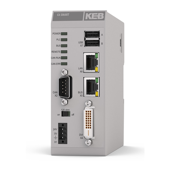
PRODUCT DeSCRIPTION 2.2 front view X7: 2 x USB 2.0 X6 LAN: 10/100/1000Mbps Ethernet; RJ45 socket with signal LEDs (link/speed). X5 BUS: 1 x 10/100Mbps Ethernet; socket RJ45. Port is used as EtherCAT mas- ter. X4 DVI-D interface: The DVI-D is used to connect a monitor. X1 voltage supply via a separate power supply unit for 18-30V (protected against polarity reversal / 500V test voltage);... -
Page 20: C6 Smart With Can Option
PRODUCT DeSCRIPTION 2.2.1 C6 SMART with CAN option X7: 2 x USB 2.0 X6 LAN: 10/100/1000Mbps Ethernet; RJ45 socket with signal LEDs (link/speed). X5 BUS: 1 x 10/100Mbps Ethernet; socket RJ45. Port is used as EtherCAT mas- ter. X4 DVI-D interface: The DVI-D is used to connect a monitor. X1 voltage supply via a separate power supply unit for 18-30V (protected against polarity reversal / 500V test voltage);... -
Page 21: C6 Smart With Multi Serial Option
PRODUCT DeSCRIPTION 2.2.2 C6 SMART with MULTI SeRIAL option X7: 2 x USB 2.0 X6 LAN: 10/100/1000Mbps Ethernet; RJ45 socket with signal LEDs (link/speed). X5 BUS: 1 x 10/100Mbps Ethernet; socket RJ45. Port is used as EtherCAT mas- ter. X4 DVI-D interface: The DVI-D is used to connect a monitor. X1 voltage supply via a separate power supply unit for 18-30V (protected against polarity reversal / 500V test voltage);... -
Page 22: Side View
PRODUCT DeSCRIPTION 2.3 Side view E-Bus: LVDS interface (with C6 Remote IO compatible connector). On that con- nector, 5V/3A power output is available. Carrier rail mount and functional earth Figure 4: Side view 2.4 bottom view RESET: Pushing this button, a processor reset is requested. RESTORE factory default: When pressed, the C6 SMART returns to factory de- fault values Figure 5:... -
Page 23: Labels
PRODUCT DeSCRIPTION 2.5 Labels Figure 6: Labels 2.5.1 Operating System (OS) and CODeSyS label OS label CODESYS label Figure 7: OS marking and CODESYS... -
Page 24: Product Labels
PRODUCT DeSCRIPTION 2.5.2 Product labels Model CE marking Electrical information Material number Serial number UL marking Figure 8: Product labels 2.5.3 IP address label Default setting (x6) IP SubNet Customer setting (x6) IP SubNet Figure 9: IP address label... -
Page 25: Combivis Connect Label
PRODUCT DeSCRIPTION 2.5.4 COMbIVIS connect label Serial number Barcode License key QR code Figure 10: COMBIVIS connect label 2.5.5 COMbIVIS studio HMI label Serial number Barcode Figure 11: COMBIVIS studio HMI label... -
Page 26: C6 Smart In Operation
PRODUCT DeSCRIPTION 2.6 C6 SMART in operation C6 SMART is a multi-purpose CPU, which can be used for control and human machine interface applications (latter on Quad Core only). The computer can be maintained re- motely via COMBIVIS connect. C6 SMART can be equipped with various IOs direct connected on the right side of the CPU. -
Page 27: Process Management
PRODUCT DeSCRIPTION 2.6.2 Process management Process management is a two-way communication between C6 SMART device and Panel PC, Embedded HMI (connected via Ethernet port) or Monitors (connected via DVI_E). Figure 13: Process management... -
Page 28: Software Options
PRODUCT DeSCRIPTION 2.7 Software options KEB wants to provide to its customers the latest technology in term of hardware and software functionality. For this reason, the products are constantly updated in both di- rections. Because of this, we can summarize the macro functionality per type of application: PLC –... -
Page 29: Installation And Connection
Check the package content for visible signs of transport damage and for complete- ness. • In the case of damaged parts, contact your KEB representative. Do not install parts that were damaged during the shipment. 3.3 Checking the operating conditions •... -
Page 30: Damage Due To Overheating
• Mounting angle: a) The system is intended to be mounted vertically. b) For other installation modes contact KEB. For installation in control cabinets and, in particular, in closed containers, make sure the recommended ambient temperature is maintained. 3.6 Mounting the device 3.6.1 DIN-rail mounting (snap in) -
Page 31: To Connect C6 Smart With Io Modules
INSTALLATION AND CONNeCTION 3.6.2 To connect C6 SMART with IO modules • After you have snapped the first module (Controller) on the mounting rail, snap the second module to the right in about 1cm distance to the first module on the mounting rail. • Push the second module along the mounting rail towards the first module until you hear the locking device snap in. 3.6.3 Disconnecting two modules • Push down the unlock button of the module that you wish to disconnect from the module to the left of it. -
Page 32: Connecting The Device
INSTALLATION AND CONNeCTION 3.7 Connecting the device 3.7.1 Notes on connection • C6 SMART must be installed in accordance with the indications contained in this operating instruction. • These devices are intended to be connected to a “Secondary Circuit Overvoltage Category II”. -
Page 33: Switching On And Testing C6 Smart
INSTALLATION AND CONNeCTION EMC ground (0V) - (0V) + (24V) Figure 16: Power supply connection details 3.7.4 Switching on and testing C6 SMART • Connect the power supply cable to C6 SMART. • Switch on the power supply. • The “Power” LED will light. Figure 17: Initialisation of the C6 SMART If any cable is connected to the DVI port, the display will switch on accordingly, and after... -
Page 34: Connecting User Computer To C6 Smart
INSTALLATION AND CONNeCTION 3.8 Connecting user computer to C6 SMART You can connect the software tools to C6 SMART using an Ethernet cable connected to Ethernet port (X6). Please note that the C6 SMART is equipped with a static IP address. In case the user likes to change the IP address (for example to 172.17.17.182) or acti- vate the DHCP, you can follow the procedure which is described below: Figure 18:... -
Page 35: Figure 20: Opening Control Panel
INSTALLATION AND CONNeCTION • If you want to get an IP address from a DHCP server choose “Obtain an IP ad- dress via DHCP” instead. • Click on “OK” to adopt the settings and close the dialog. • Click on the “Start” button and select “Settings” -> “Control Panel”. Figure 20: Opening Control Panel •... -
Page 36: Activation Of The Touch Driver
INSTALLATION AND CONNeCTION Figure 22: Saving the register 3.9 Activation of the touch driver To activate the touch driver, the corresponding *.bat file must be executed. Tools\ mmcmemory tools\ ActivateEgalaxCapacitiveTouch.bat ActivateEgalaxCapacitiveTouch180.bat ActivateEgalaxResistiveTouch.bat After that it is absolutely necessary to perform a "Registry-Save".The driver calibration can be carried out via Windows\eGalaxTouch.exe. -
Page 37: Commissioning Of The Device
COMMISSIONING Of THe DeVICe 4 Commissioning of the device 4.1 Mass storage C6 SMART comes as standard with several memories: the experience in industrial au- tomation environments and application impose, on our development, a separation be- tween system and application mass storage. The following table wants to show the components available for both Controller type (Dual and Quad core). -
Page 38: Signaling And Diagnostic Leds
COMMISSIONING Of THe DeVICe 4.2 Signaling and diagnostic LeDs The following table describes all the LEDs meaning and behaviors. Name Description Operation Display • Green, on C6 SMART and C6 Remote IO module is ready for operation. • Red, on The C6 SMART is not ready for operation. -
Page 39: Push-Buttons
COMMISSIONING Of THe DeVICe 4.3 Push-buttons C6 SMART is equipped with two push buttons located on the bottom side of the device. These buttons can be useful for CPU reset or even restore default setup. The following table provides more details: Name Description Reset... -
Page 40: Commissioning A Project
COMMISSIONING A PROjeCT 5 Commissioning a Project 5.1 COMbIVIS studio 6 project 5.1.1 Project implementation The CONTROL PLC runs as a thread with “real time” priority. The execution model is based on the “task” concept; the program execution requires the definition of tasks and the assignment of priority and execution cycle according to the following figure (see below in this manual about how to configure COMBIVIS studio 6 for use with C6 SMART system). -
Page 41: Figure 24: Task Configuration For Ethercat Master Task
If this is the case, the task cycle time should be properly increased until you reach the proper balancing between performances and reactivity of the whole system. To avoid cycletime overflows the KEB gateway must not run in the EtherCAT task! Trace is not running properly on EtherCAT external task, if task load is higher... -
Page 42: Transferring The Combivis Studio 6 Application To The Target System
COMMISSIONING A PROjeCT 5.1.2 Transferring the COMbIVIS studio 6 application to the target system To transfer a valid “COMBIVIS studio 6” application to the target system, follow these steps: • Ensure the C6 SMART device is connected to the same sub network of the PC where you have running the COMBIVIS studio 6 programming tool (same network mask, e.g. -
Page 43: Support For Retentive Data
COMMISSIONING A PROjeCT 5.1.4 Support for retentive data C6 SMART systems are equipped with a Micro UPS specifically designed to support the data memory retention. In COMBIVIS studio 6 the retentive variables can retain their value throughout the usual program run period. They are declared as “Retain Variables” or even more stringent as “Persistent Variables”. -
Page 44: Figure 28: Start Cdslaunchmgr.exe
COMMISSIONING A PROjeCT The available retentive memory size is 64kB for the RETAIN memory type and 64kB for the PERSISTENT memory type. If the power supply returns before the energy inside the Micro UPS is finished, and actually C6 SMART has not been switched off, the following operations are carried on: - The display is switched on. - The USB ports are powered. - CONTROL runtime behavior can be selected in between 3 possible models: a. -
Page 45: Figure 29: Cds Launch Manager
COMMISSIONING A PROjeCT The launcher manager interface is shown in the following figure. Figure 29: CDS Launch Manager The parameter "Wait for CDS start" is the time the launcher waits before starting the CONTROL runtime. "Restart timeout" is the time the launcher waits before restarting CONTROL runtime. Figure 30: Restart time-out... -
Page 46: Use In Combination With Combivis Hmi Runtime
COMMISSIONING A PROjeCT Figure 31: Restart time-out 5.1.5 Use in combination with COMbIVIS HMI Runtime COMBIVIS HMI Runtime can be of course configured to communicate with the “COM- BIVIS studio 6” application. The C6 SMART includes the COMBIVIS studio 6 Gateway which is then used as com- munication interface. The COMBIVIS studio HMI project must be configured to communicate with a generic CoDeSys controller inserting in the “Real Time DB” resource the driver called “ CoDe- Sys” as shown in the following figure. -
Page 47: Figure 33: Device Name In Combivis Studio 6
COMMISSIONING A PROjeCT The station must be configured to connect to “localhost”. The device name is the one shown by the programming system COMBIVIS studio 6 when connected online with the C6 SMART device from the “Communication settings” window as shown in the following figure. Figure 33: Device Name in COMBIVIS studio 6 The HMI Station properties will result as following. Figure 34: Station properties... -
Page 48: Use In Combination With Combivis Connect
COMMISSIONING A PROjeCT The CONTROL Runtime running on a C6 SMART device can be reached also from a panel which has been configured to belong to the same sub network. When having on the same sub network more than one C6 SMART system, you need to assign different names to them. The COMBIVIS studio HMI project can be configured to communicate with more than one controller;... -
Page 49: Combivis Studio Hmi Project
COMMISSIONING A PROjeCT 5.2 COMbIVIS studio HMI project 5.2.1 Overview Configuration phase A project includes screen, alarms, variables used to represent the real plant of machine. The configuration phase is the creation of the project according to the user needs and interaction between the humans and the machine. Transferring the project to C6 SMART You can transfer a project to C6 SMART as follows: •... -
Page 50: Figure 35: Opening Control Panel
COMMISSIONING A PROjeCT C6 SMART comes as default with the serial port set as RS 232. If you want to change the type of serial communication you must do the following: • Go to "Control Panel" Figure 35: Opening Control Panel •... -
Page 51: Connecting The Serial Port
5.2.4 Connecting the serial port A special DB15 connector supports all serial protocols. Therefore it is necessary to adapt the connections to the technical requirements; KEB can supply connector adapters as optional parts but user can adapt DB15 connector by himself. -
Page 52: Stopping The Running Project
COMMISSIONING A PROjeCT 5.2.6 Stopping the running project Figure 39: Stopping the running project To stop a project running in C6 SMART you must: • Select TCP in the upper left list. • Write the IP address of C6 SMART. •... -
Page 53: Starting The Project
COMMISSIONING A PROjeCT 5.2.7 Starting the project Figure 41: Starting the project To start a project in C6 SMART by using the configuration PC you must: • Select TCP in the upper left list. • Write the IP address of C6 SMART. • Click on the button “Start Device Project” The C6 SMART project starts. Figure 42: Starting the project... -
Page 54: Debugging The Project
COMMISSIONING A PROjeCT 5.2.8 Debugging the project You can debug the project in C6 SMART by connecting with the configuration PC. In order to be able to use the debugging functionality you must prepare your project as follows: • Select “Networking” in the project explorer window of COMBIVIS studio HMI. • Enable the property “Debugger” in the "Properties" window of COMBIVIS studio HMI. -
Page 55: Figure 44: Debugging The Project
COMMISSIONING A PROjeCT Figure 44: Debugging the project The following window will appear: Figure 45: Debugging the project Enter the IP address of the C6 SMART and click "OK". A new window opens and asks for the user and password. -
Page 56: Transfer The Project From The C6 Smart To The Configuration Computer
COMMISSIONING A PROjeCT Figure 46: Enter password In case the project is not protected, just click on the “OK” button, otherwise insert the name and password of a project user that has the rights to change the project. A debug session starts in COMBIVIS studio HMI on the configuration PC. Now you are able to: •... -
Page 57: Backup And Restore
C6 SMART has tools to backup and restore the contents of its internal memory in order to manage the project and the operating system of C6 SMART. For more information please contact the support center of KEB. 5.2.11 Updating the operating system... -
Page 58: System Manager
SySTeM MANAGeR 6 System Manager 6.1 System Manager The system manager is a utility which is available for all ARM and x86 based KEB sys- tems with WinCE operating system. It is available as built-in component of the operating system. -
Page 59: Backup Restore
SySTeM MANAGeR System Reboot Figure 49: System Manager Control Panel Applets 6.1.1 backup Restore The “Backup Restore” utility interface is shown in the following figure. The utility provides two functions: • System clone and Restore • Selective functions Backup and Restore Before starting Backup or Restore operations the CONTROL runtime should be stopped. - Page 60 SySTeM MANAGeR The clone operation has two optional settings: • Operating system image: allows to create a clone of the operating system ROM image. • Custom registry keys: allow to specify custom keys to be saved in the backup. Click “Run” to start the process. You will be asked to provide a path where to store the clone snapshot.
- Page 61 SySTeM MANAGeR To start the selective backup, click the button "Backupfeatures into a .ASR repository". The utility will display a list of available features and settings to be saved. The window is self-explain, follow the instructions on the screen and mark the check box of the desired features you need to backup.
-
Page 62: Font Antialiasing
SySTeM MANAGeR 6.1.3 font Antialiasing The utility allows to set the font quality rendering options. Double click on the Control Panel icon and select the desired rendering option. Click OK to confirm. The settings are automatically saved to the registry and no manual saving is required. Figure 51: Font Antialiasing 6.1.4 eMMC Usage... -
Page 63: Kiosk Mode
SySTeM MANAGeR 6.1.5 Kiosk mode The utility allows to enable the kiosk mode. When enabled, the panel will start directly the HMI Runtime with related project without showing the Windows CE Explorer. Figure 53: Kiosk mode To enable kiosk mode, just open the utility and mark the “Enable kiosk mode” in the check box. -
Page 64: Language Settings
SySTeM MANAGeR Figure 54: Launch Explorer from COMBIVIS connect HMI 6.1.6 Language settings The utility provides fonts installation for the Chinese, Japanese and Korean languages. Figure 55: Language settings 6.1.7 Scrollbar The utility allows to change the size of the windows scrollbars. This is useful when cre- ating applications with HMI because some of the standard controls get the scrollbar size information from the operating system. -
Page 65: System Reboot
SySTeM MANAGeR 6.1.8 System Reboot The utility allows to reboot the system. Figure 57: System Reboot 6.1.9 Assign network settings via text file to the USB stick You have the option of assigning the network settings by using a USB stick that contains a file called IPConfig.csv. -
Page 66: Maintenance
MAINTeNANCe 7 Maintenance 7.1 Opening the C6 Smart With a screwdriver slightly force the side cover as shown in the following figures taking care not to damage it. Figure 58: Opening the C6 Smart Figure 59: Opening the C6 Smart Carefully extract the cover. Figure 60: Opening the C6 Smart... -
Page 67: Backup Battery Replacement
MAINTeNANCe Carefully extract the system from the chassis. Figure 61: Opening the C6 Smart Figure 62: Opening the C6 Smart 7.2 backup battery replacement C6 SMART has a battery for storing settings during power off phases. For a stock tem- perature of 25°C the life time of the battery is >10 years. The user can replace the battery with a new one based on the same model (Lithium CR2032 3V Coin). -
Page 68: Figure 63: Battery Area
MAINTeNANCe Figure 63: Battery area DANGeR Risk of explosion! ► Risk of explosion if the battery is replaced with an incorrect type. Dispose of used batteries according to the instructions. Figure 64: Battery details • Turn off the system and disconnect the power supply. • Remove the battery from the battery holder. Figure 65: Battery replacement... -
Page 69: Figure 66: Battery Replacement
MAINTeNANCe • Replace it with one of the same model (Lithium CR2032 3V Coin). Figure 66: Battery replacement Figure 67: Battery replacement... -
Page 70: Microsd Replacement
MAINTeNANCe 7.3 MicroSD replacement C6 SMART has an internal micro SD Card connector to accommodate a MicroSD/SDHC card slot V. 2.0 (push-push type). Slot for memory card Figure 68: Slot for memory card This card is not accessible from external. •... -
Page 71: Figure 70: Remove Memory Card
MAINTeNANCe NOTICE Potential data loss ! ► Do not remove the memory card while data is being accessed. ► Data on the memory card is lost if you attempt to remove it while C6 SMART is accessing its data. • Now the Micro SD is released and it is possible to remove it. -
Page 72: Technical Specifications
Microsoft Embedded Compact 7 (C7P) HMI (only for quad COMBIVIS HMI Runtime (BASIC, ADVANCED core) versions) Remote control COMBIVIS connect runtime Control RTE KEB Real Time Extension CONTROL RTE characteristics BASIC ADVANCED COMBIVIS connect characteristics COMBIVIS HMI characteristics (only quad core) BASIC ADVANCED... -
Page 73: Mechanical Characteristics
Depth: 124 mm weight: 420 g Table 8: Mechanical characteristics 8.4 System hardware characteristics Motherboard Model KEB C6 SMART Hardware with battery backup Processor ARM Cortex A9 - Freescale i.MX6 - 1 GHz (Dual Lite and Quad Core Plus) Memory bus... -
Page 74: Electrical Characteristics
TeCHNICAL SPeCIfICATIONS 8.5 electrical characteristics Power supply Type Integrated on board, auto ranging Input voltage 18…32 VDC with 3-pole connector Power consumption C6 SMART 19 W / 24V DC C6 SMART CAN 20 W / 24V DC C6 SMART SERIAL 20 W / 24V DC Protection Reverse polarity protection, overvoltage, fuse soldered on... -
Page 75: Battery Technical Data
TeCHNICAL SPeCIfICATIONS 8.8 battery technical data Figure 71: Battery CR2032 detail Model CR2032 MfR renata Chemical System Li / MnO2 Nominal Voltage Rated Capacity 225 mAh Temperature range -30°C - +70°C Self discharge at 23°C < 1% / year Table 13: Battery technical data Figure 72: Battery performance... -
Page 76: Dimension Drawings
TeCHNICAL SPeCIfICATIONS 8.9 Dimension drawings Figure 73: C6 SMART side view Figure 74: C6 SMART front view... -
Page 77: Ports Pinout
TeCHNICAL SPeCIfICATIONS 8.10 Ports PINOUT Signal USB A +5 Vcc USB Data - USB Data + Table 14: USB A Signal USB B +5 Vcc USB Data - USB Data + Table 15: USB A 8.10.1 CAN X2 Signal CAN_L CAN_GND CAN_SHLD CAN_GND... -
Page 78: Dvi-D X4
TMDS DATA 1+ TMDS DATA 1/3 SHIELD +5V POWER Table 17: 8.11 Technical support & repairs KEB offers complete after-sales technical support. The staff who deal with this handle questions on the entire range of products skillfully, quickly, and efficiently. You can phone our staff in the service department, and they will give you complete, prompt advice on how to resolve your problems. telephone:... -
Page 79: Certification
CeRTIfICATION 9 Certification 9.1 Mark of conformity... - Page 80 CeRTIfICATION...
-
Page 81: Tüv Certificate
NRAQ.E479848 - Programmable Controllers | UL Product iQ https://iq.ulprospector.com/de/profile?e=86751 NRAQ.E479848 - Programmable Controllers Programmable Controllers See General Information for Programmable Controllers KEB AUTOMATION KG E479848 SUEDSTRASSE 38 32683 BARNTRUP, GERMANY Investigated to ANSI/UL 508 Front-Panel Mounting Display, for use on a flat surface of a type 1 and 4X INDOOR enclosure, Model(s) aaC6AF1-44xx Where "a" may be any character for different sizes of panel display. -
Page 82: Notice
NOTICe Notice... - Page 83 Tel: +33 149620101 Fax: +33 145767495 c / Mitjer, Nave 8 - Pol. Ind. LA MASIA E-Mail: info@keb.fr Internet: www.keb.fr 08798 Sant Cugat Sesgarrigues (Barcelona) Spain Tel: +34 93 8970268 Fax: +34 93 8992035 E-Mail: vb.espana@keb.de Germany Geared Motors KEB Antriebstechnik GmbH...
- Page 84 Automation with Drive www.keb.de KEB Automation KG Suedstrasse 38 32683 Barntrup Tel. +49 5263 401-0 E-Mail: info@keb.de...
Need help?
Do you have a question about the COMBICONTROL C6 SMART and is the answer not in the manual?
Questions and answers