KEB COMBIVERT F5 series Installation Manual & Operation Manual
1/2 - 1hp 230v
Hide thumbs
Also See for COMBIVERT F5 series:
- Instruction manual (116 pages) ,
- Instructions for use manual (72 pages) ,
- Installation manual (46 pages)

Subscribe to Our Youtube Channel
Related Manuals for KEB COMBIVERT F5 series


Summary of Contents for KEB COMBIVERT F5 series
- Page 1 C O M B I V E R T � Installation Guide & Operation Manual A-Housing B Control 1/2 - 1 hp 230 V 02/2006...
- Page 2 This manual describes the KEB COMBIVERT F5 series motor control. This manual focuses attention on installation, connection as well as basic operation. Due to the various application possibilities and extensive programming capabilities with this unit, it was necessary to provide separet documentation which contains all of this detailed information.
-
Page 3: Table Of Contents
Contents Table of Contents 1. Saftey and Operating Instructions ..........5 2. Product Description ..............6 2.1 Application ..................6 2.2 Part number identification ..............6 2.3 Technical Data .................7 2.3.1 230 V-class ..................7 2.4 Dimensions and terminals ...............8 3. Installation and Connection ............9 3.1 Control Cabinet Installation .............9 3.2 Good EMC Installation Techniques ..........10 3.3 Connection of Power Circuit ............ - Page 4 Contents 4.2 Parameter Summary ..............19 4.3 Password Input ................20 4.4 Operating Displays ................20 4.5 Basic Adjustment of the Drive ............22 4.6 Special Adjustments ..............25 4.7 The „Drive Mode“ ................37 4.7.1 Start / Stop Drive ................37 4.7.2 Changing the Direction of Rotation ...........37 4.7.3 Speed setting ..................37 4.7.4 Leaving the „Drive Mode“...
-
Page 5: Saftey And Operating Instructions
RISK OF ELECTRIC SHOCK! Allways disconnect the supply volt- local codes and accident prevention rules!). age before installing or servicing the KEB COMIBIVERT F5 motor For the purposes of these basic safety instructions, ”skilled techni- control! Wait five minutes for the before attempting to change any cal personnel“... -
Page 6: Product Description
2. Product Description 2.1 Application The KEB COMBIVERT F5 series motor control is designed exclusively for the control and regulation of induction motors. The operation of other electric devices and loads is prohibited and can lead to the destruction of the unit. -
Page 7: Technical Data
1) Rated operation means rated switching frequency, rated voltage, and rated output current. 2) Only for units with the braking circuit installed. 3) Maximum cable length is based on the the use of shield motor cables, ground current limitations, EMI levels set forth in EN55011. Contact KEB for more information. -
Page 8: Dimensions And Terminals
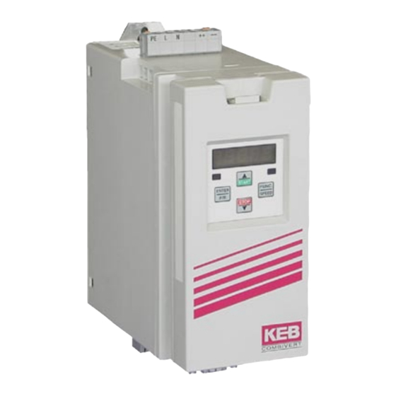
Product Description 2.4 Dimensions and terminals Weight 1/2 kg / 1 lb X1A Connection from the line X1B Connection to the motor, brake resistor, temp sensor X2A Connectin for control cables X4A Connection for Operator/display HSP5-Servicecable Connection for shield / ground Pay attention to the input voltage, since both 230 V and 460 V units (3-phase) are pos- sible. -
Page 9: Installation And Connection
ANTRIEBSTECHNIK ANTRIEBSTECHNIK Installation requirements: • Mount in a stationary location with low vibration. Contact KEB when mounting on a moving system. • Adhere to minimum clearance distances in diagram 3.1. Mul- tiple units can be mounted side by side with zero clearance. -
Page 10: Good Emc Installation Techniques
• Connect the control panel to the sub panel with a heavy ground strap. If a KEB EMI (CE) filter is used, it must be mounted as close as possible and to the same subpanel as the COMBIVERT F5 motor control. The filter must have large bare surface contact with the subpanel. -
Page 11: Connection Of Power Circuit
COMBIVERT F5. Wait 5 minutes before attempting to change the connections as the DC Bus capacitors may still be charged. Absolutely pay attention to the nameplate voltage of the KEB COMBIVERT and the connected line voltage. A 230V-unit will be immediately destroyed on a 460V-power supply. -
Page 12: Line Connection Terminal X1.A
• Power connection must be installed as indicated on the previous page. Always be sure to double check power connections for tightness. • For installation requiring line side ground fault protection (GFI) consult KEB. • Line chokes can be used to reduce harmonics, conducted high frequency noise, and can extend the lifetime of the unit. -
Page 13: Motor Connection
Installation and Connection 3.3.4 Motor connection Terminal X1B provides connections for: • ++, PB Braking resistor • U, V, W Motor • T1, T2 Temperature sensor ���� Th e maximum � �� m o t o r c a b l e ��... -
Page 14: Connection Of The Braking Resistor
07.BR.100-1180 PD = continuous power disapation in watts, P6 = peak repetitive power disapation with a sec on time and 120 sec cycle time. KEB can offer many types of braking resistors, please contact your sale representative for more information. -
Page 15: Control Circuit: F5-Basic
Installation and Connection 3.4 Control Circuit: F5-BASIC 1 5 7 8 10 11 14 15 16 20 22 24 25 26 27 28 29 3.4.1 Terminal Strip Connections Function Name Description + Analog input 1 Voltage input for speed resolution: 11 Bit, 0...±10 VDC ^ 0...±CP .11, scan time: 2 ms Analog output 1 ANOUT1 Analog output of the actual... -
Page 16: Digital Inputs
Installation and Connection 3.4.3 Digital Inputs Use of internal voltage supply ��� � �� �� �� �� �� �� �� ��� Use of external voltage supply ��� � �� �� �� �� �� ��� ��� Rin = 2.1 k٠� 20...30 VDC Regulated 3.4.4 Analog Inputs External analog... -
Page 17: Operation Of The Inverter
Operation of the Drive 4. Operation of As an accessory for displaying and editing "CP" parameter values, a "digital operator" is necessary. To remotely mount the digital operator, the inverter a operator remote cable is required (option: cable 00.F5.0C0-1xxx). To prevent malfunctions, the inverter must be brought into nOP status (remove signal from control release terminal 16) before connecting/ disconnecting the operator. -
Page 18: Keypad
Operation of the Drive 4.1.1 Keypad When switching on the KEB COMBIVERT F5, the value of parameter CP .1 appears in the operator display. (see "Drive Mode" to switch the keypad function) The function key (FUNC) changes be- FUNC. tween the parameter... -
Page 19: Parameter Summary
Operation of the Drive 4.2 Parameter Summary Display Parameter Setting range Resolution Factory setting CP. 0 Password input 0...9999 – CP. 1 Actual frequency display – 0.0125 Hz – CP. 2 Set frequency display – 0.0125 Hz – CP. 3 Inverter status display –... -
Page 20: Password Input
Operation of the Drive 4.3 Password From the factory, the frequency inverter is supplied without pass- word protection, this means that all parameters can be adjusted. Input After programming, the unit can be protected against unauthorized access thus preventing the values from being changed. FUNC. - Page 21 Operation of the Drive "Forward Acceleration" drive accelerates with direction of rota- tion forward . "Forward Deceleration" drive decelerates with direction of rotation forward. "Reverse Acceleration" drive accelerates with direction of rota- tion reverse. "Reverse Deceleration" drive decelerates with direction of rotation reverse.
-
Page 22: Basic Adjustment Of The Drive
Operation of the Drive Actual DC voltage This display makes it possible to recognize instantaneous voltage peaks peak value within an operating cycle. The highest value of CP.7 is stored in CP.8. The peak value in memory can be cleared by pressing the UP, DOWN or ENTER key or by writing any value you like to the address of CP.8. - Page 23 Basic Adjustment of the Drive Acceleration time The parameter determines the time needed to accelerate from 0 Hz to 100 Hz. The actual acceleration time is proportional to the frequency change. 100 Hz –––––– x actual acceleration time = CP.12 delta f 100 Hz Adjustment range:...
- Page 24 Basic Adjustment of the Drive Ramp adjustment with S-curves t1 = S-curve time (CP.14) t2 = Acceleration time (CP.12) +f [Hz] t3 = Deceleration time (CP.13) t [s] -f [Hz] In the lower speed range losses in the motor become greater. This parameter Boost can be used to boost the voltage in order to overcome these losses.
-
Page 25: Special Adjustments
Basic Adjustment of the Drive 4.6 Special Adjustments The following parameters serve for the optimization of the drive and the adaptation to certain applications. These adjustments can be ignored at initial start-up. This parameter can be used to regulate the output voltage in relation to the Voltage rated frequency. - Page 26 Special Adjustments Carrier frequency The frequency with which the power modules are switched can be changed depending on the application. The employed power stage determines the maximum switching frequency as well as the factory setting. Generally, the inverter can operate at frequencies higher than the rated value but not under continuous load.
- Page 27 Special Adjustments DC-braking Mode During DC-braking, the motor is not decelerated by a controlled ramp. Quick braking without regen voltage can be achieved by applying a DC voltage to the motor winding. Parameter values listed below, determine how the DC-braking is triggered. Value DC-Braking Activation Deactivated Activates when direction signal is removed and the output frequency...
- Page 28 Special Adjustments Max. ramp current This function acts as an adjustable current limit during acceleration or deceleration. It can be used to prevent the load current from exceeding the inverter's peak current rating, thereby preventing shut down with an E.OC fault.
- Page 29 Special Adjustments Speed search When starting the frequency inverter into a spinning motor, an E.OC fault condition can be triggered because of the difference between the actual motor speed and the inverter set speed. By activating speed search, the inverter searches for the actual motor speed, adjusts its output frequency to match.
- Page 30 Special Adjustments Response to This parameter determines the response of the drive to the external tem- external overtem- perature monitoring circuit. In order to activate this function the power circuit perature terminals T1, T2 must be connected in accordance with the instruction manual, see page 14.
- Page 31 Special Adjustments Analog output 1 CP.29 defines the function of analog output 1. Value Function Absolute actual frequency (CP.1) 100Hz= 100% Absolute set frequency (CP.2) 100Hz= 100% Actual frequency (CP.1) ±100Hz= 100% Set frequency (CP.2) ±100Hz= 100% Output voltage (CP.9) 500V= 100% Actual DC voltage (CP.7) 1000V= 100%...
- Page 32 Special Adjustments Relay output 1 CP.31 and CP.32 determine the function of the two outputs. CP.31 for relay output 1 (terminal X2A.24...X2A.26) CP.32 for relay output 2 (terminal X2A.27...X2A.29) Relay output 2 The switching level of CP.32 is CP.33! Value Function No function On;...
- Page 33 Special Adjustments Value Function Set value on AN3 > switching level {F5G only} Timer 1 > switching level Timer 2 > switching level Reserved {F5M} Hardware current limit active Modulation on-signal ANOUT3 PWM ANOUT4 PWM {F5G only} Inverter status (ru.0) = switching level Power transistor temperature >...
- Page 34 Special Adjustments Relay output 2 This parameter determines the switching point for the relay output 2 (CP.32). Switching level After the switching of the relay, this value can move within a 0.5 Hz window (hysteresis), without the relay changing states. Since the operator display can only view 5 characters, the last digits are not displayed for the higher values.
- Page 35 Special Adjustments Set value internal intern 0-limited 100% (Value 2 and 4) external extern -100% 100% -100% -10V internal intern Set value 100% absolute (Value 3 and 5) external extern -100% 100% -100% -10V Adjustment range: 0...9 Resolution: Factory setting: Note: Enter-Parameter AN1 Interface...
- Page 36 Special Adjustments AN1 Zero point Noise coupled capacitively or inductively into the analog signal wires can hysteresis cause the motor to drift in spite of the filtering of the analog input. The zero point hysteresis can be used to suppress this noise and therefore prevent the motor from drifting.
-
Page 37: The "Drive Mode
Drive Mode 4.7 The "Drive Mode" The Drive Mode is a operating mode of KEB COMBIVERT that permits the manual starting of the through the keypad display unit. After applying a signal to the control release terminal 16, the set value (speed ref.) and rotation setting are effected exclusively over the keypad. -
Page 38: Error Diagnosis
Error Diagnosis 5. Error Diagnosis KEB COMBIVERT Error messages are always represented with an "E.xx" and the appropriate error code in the display. Errors cause the immediate turn off of the output to the motor. Restart is possible, only after reset. - Page 39 Error Diagnosis • motor overloaded • line breakage to the temperature sensor E.nEd no ERROR detected No defined error recognized (should not occur) E.ndOH no ERROR drive overheat No longer overtemperature of motor Temperature SENSOR, SENSOR is again low-resistance. E. PU ERROR power unit Error: General power circuit fault NO.PU...
- Page 40 Error Diagnosis E.CO1 ERROR counter overrun 1 Error: Counter overflow encoder channel 1 E.CO2 ERROR counter overrun 2 Error: Counter overflow encoder channel 2 E. BR ERROR brake Error: This error can occur in the case of switched on brake cont- rol, if the load is below the minimum load level Pn.58 (application mode) at start up.
-
Page 41: Quick Reference
6. Quick Reference Display Parameter Adjust. range Resolution Cust. setting CP . 0 Password input 0...9999 read only CP . 1 Actual frequency display – 0.0125 Hz read only CP . 2 Set frequency display – 0.0125 Hz read only CP . - Page 42 FUNC. SPEED Parameter Display When switching on the KEB COMBIVERT F5, the value of parameter CP .1 appears in the operator display. (see "Drive Mode" to switch the keypad function) The function key (FUNC) changes between the parameter value and parameter number.
- Page 43 Part 2 Power Circuit for complete power range • Part 3 Control Circuit for B/G, M, or S version Service notes • Up/Download of parameter lists with KEB COMBIVERT • Error messages Detailed Instructions and information for application design and development •...
- Page 44 KEB Polska mail: vb.belgien@keb.de ul. Budapesztańska 3/16 • PL–80-288 Gdańsk fon: +48 58 524 0518 • fax: +48 58 524 0519 KEB Power Transmission Technology (Shanghai) Co. Ltd. mail: vb.polska@keb.de Industry Development District No. 28 Dongbao Road Song Jiang KEB Taiwan Ltd.
Need help?
Do you have a question about the COMBIVERT F5 series and is the answer not in the manual?
Questions and answers