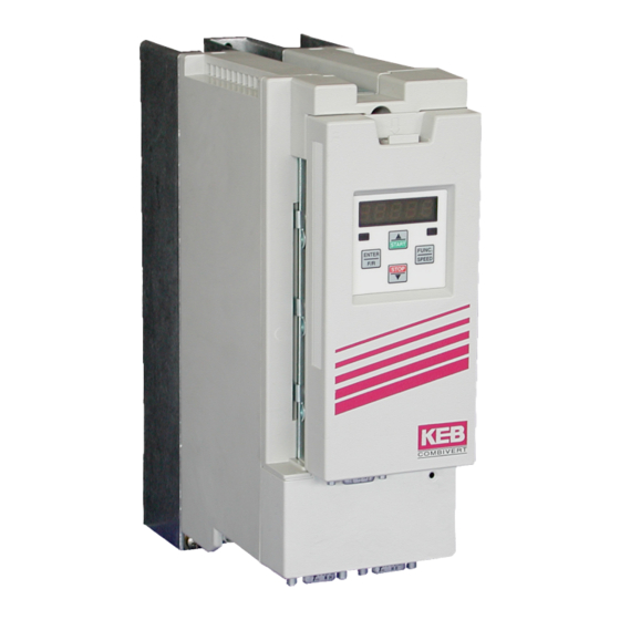
KEB COMBIVERT F5 Installation Manual
Digital servo controller
Hide thumbs
Also See for COMBIVERT F5:
- Applications manual (378 pages) ,
- Reference manual (349 pages) ,
- Instruction manual (196 pages)

Related Manuals for KEB COMBIVERT F5


Summary of Contents for KEB COMBIVERT F5
- Page 1 C O M B I V E R T The general EMC and safety directions at www. keb.de have to be observed ! Installation Manual Housing A Mat.No. Rev. 00F5SEM-KA03...
- Page 2 This manual describes the KEB COMBIVERT F5. Particular attention is paid to the installation, the connection as well as the basic operation. Due to the various application and programming possibilities, the application-specific connection and/or wiring diagram, the parameter adjustment as well as instructions to the start-up are to be taken from the documentation of the machine manufacturer.
-
Page 3: Table Of Contents
3.3.6 Connection of a braking resistor with temperature monitoring in accordance with UL ..14 Encoder interface connection .....................14 3.4.1 Resolver connection at KEB motors with connector X3A ...........14 3.4.2 Incremental encoder input / -emulation X3B ..............15 Control board Servo ......................16 3.5.1 Control terminal strip X2A....................16... -
Page 4: Safety And Operating Instructions
Important, absolutely read Safety and Operating Instructions Safety and Operating Instructions for drive converters (in conformity with the Low-Voltage Directive 2006/95/EC) 1. General (potential health risks). In operation, drive converters, depending on their degree of 5. Electrical connection protection, may have live, uninsulated, and possibly also moving When working on live drive converters, the applicable national or rotating parts, as well as hot surfaces. -
Page 5: Product Description
The operation of other electric consumers is prohibited and can lead to the destruction of the unit. On delivery the controllers are tuned to the servo motors supplied by KEB. Servo controllers are components which are intended for the installation in electric systems or maschines. -
Page 6: Technical Data
Product description Technical data Inverter size Housing size Phases Output rated power [kVA] Output rated current Output rated current UL Stand still current Max. short time current OC-tripping current Rated switching frequency [kHz] Max. switching frequency [kHz] Power loss at nominal operating Power loss at DC operating Heat sink power losses Heat sink power losses (DC) - Page 7 Inverter size Housing size Phases Output rated power [kVA] Output rated current Output rated current UL Stand still current Max. short time current OC-tripping current Rated switching frequency [kHz] Max. switching frequency [kHz] Power loss at nominal operating Power loss at DC operating Heat sink power losses Heat sink power losses (DC) Minimum braking resistor...
- Page 8 Site altitude maximal 2000 m above sea level. With site altitudes over 1000 m a derat- ing of 1 % per 100 m must be taken into consideration. Overload function GB - 8...
-
Page 9: Dimensions And Terminals
Product description Dimensions and Terminals U, V, W Connection for servo motor PA, PB Connection for braking resistor T1, T2 Connection for temperature sensor / switch L1, N/L2, L3 1/3-phase mains connection (230V-class) L1, L2, L3 3-phase mains connection (400V-class) ++, -- DC voltage supply in-/output for DC-supply networks 250...370 V DC (230V class) -
Page 10: Installation And Connection
- ideal in a metal cable duct. • Mount COMBIVERT well conducting with the mounting plate. Remove the paint before- hand. You can find further instructions regarding the EMC-conform wiring in the Internet at KEB. GB - 10... -
Page 11: Connection Of Power Circuit
• DC-Supply 420…747 V DC (++, --) • DC-Supply 250…370 V DC (++, --) Absolutely observe the connecting voltage of the KEB COMBIVERT. A 230V-unit will be immediately destructed on a 400V-power supply. Never exchange the mains and motor cables. -
Page 12: Mains Connection
Installation and Connection 3.3.3 Mains connection Mains connection 230 V 1-phase Mains connection 230 V 3-phase 3 x 1.5 mm² 4 x 1.5 mm² X1.A X1.A N/L2 N/L2 3 x 230 V AC 1 x 230 V AC Mains connection 400 V 3-phase Protection •... -
Page 13: Connection Of The Temperature Monitoring
Installation and Connection • Plug in all connectors only in off-circuit condition ! • Observe correct phase sequence of the motor ! • Shielded motor line Motor connector X1.B gr/ye ext. brake supply unit Brake + with own voltage supply Brake –... -
Page 14: Connection Of A Braking Resistor With Temperature Monitoring In Accordance With Ul
! Encoder interface connection The plugs may only be connected / disconnected when the inverter and supply voltage are disconnected ! 3.4.1 Resolver connection at KEB motors with connector X3A • Maximum line length 50 m Housing Housing... -
Page 15: Incremental Encoder Input / -Emulation X3B
RJ45-Connector assignment free free free free green REF+ blue SIN+ SIN - yellow REF- gray COS+ pink COS- 3.4.2 Incremental encoder input / -emulation X3B The encoder interface X3 is switchable from an incremental encoder emulation to an in- cremental encoder input. The increments of the emulation are fixed to 1024 for units with resolver interface. -
Page 16: Control Board Servo
Installation and Connection Control board Servo 3.5.1 Control terminal strip X2A • Tightening torque 0.22…0.25 Nm (2 lb inches) 1 2 5 7 8 10 11 12 13 16 18 19 21 22 24 25 26 • Use shielded/drilled cables •... -
Page 17: Connection Of The Control Terminal Strip
Installation and Connection 3.5.2 Connection of the control terminal strip Set value signal Set value potentiometer 0…±10 V DC 3…10 kΩ analog output ±10 V DC max. 5 mA external voltage supply 20…30 V DC ±0 % max. 30 V DC 0.01…1 A Connect potential equalizing line only if a potential difference of >... -
Page 18: Operation Of The Unit
4.1.2 Digital operator (part number 00F5060-1000) As an accessory for the local operation of the KEB COMBIVERT F5 an operator is available. To prevent malfunctions, the inverter must be brought into nOP status before connecting / disconnecting the operator (open control release). When starting the inverter, it is always started with the last stored values or the factory setting. -
Page 19: Remote Control
PC / Operator Part number 00.58.025-001D Housing (PE) F5-Operator 4.1.4 Remote control For remote control of the KEB COMBIVERT F5 a special HSP5 operator is available. Operator Cable The last three digits of the part number indicate the 00F5060-9000 00F50C0-2xxx length of the cable in dm. -
Page 20: Resetting Error Messages
4.2.3 Password Input The KEB COMBIVERT is outfitted with a comprehensive password protection. In dependence on the entered password the following modes are possible: Display Mode... -
Page 21: Parameter Description For F5 Servo
ENTER (error-LED on the operator is still blinking). Status messages and information about the cause and removal are to be found in www. keb.de => Documentation => Operating Instructions => Other => Service informations => Error and status messages.doc. - Page 22 CP.20 as well. The adjustment values of known motors of the KEB COMBIVERT S4 series must be multiplied by the pole- pair number of the motor. The lower 16 bits of the result must be entered in CP.20.
- Page 23 CP-Parameter The signals A(+) and A(-) must be changed for units with SIN/COS encoder. Should this involve too much effort then you can achieve a rotation reversal of encoder 1 by means of this parameter. CP.21 Meaning Tracks not exchanged Track exchanged 2…3 Reserved for initiator input CP.28 Torque reference source...
- Page 24 CP-Parameter Value Function Absolut value ANOUT1 > switching level Absolut value ANOUT2 > switching level ANOUT1 > switching level ANOUT2 > switching level Driver voltage activ (safety relay) Absolut active power > switching level Active power > switching level Unlisted values are only for application mode Switching level of CP.33 = 100;...
-
Page 25: Annex A
Annex A Annex A Overload characteristic Release time [s] Load [%] On exceeding a load of 105% the overload integrator starts. When falling below the inte- grator counts backwards. Error E.OL is triggered if the integrator achieves the overload characteristic. Calculation of the motor voltage The motor voltage for dimensioning of the drive is depending on the used components. -
Page 26: Storage
If the capacitor starts running with rated voltage, it is tried to build the oxide film abrupt again. This causes heat and gas and leads to the destruction of the capacitor. In order to avoid defectives, the KEB COMBIVERT must be started up depending on the storage period in accordance with the following specification: Storage period <... -
Page 27: Changing The Response Threshold Of The Braking Transistor
Input voltages as before, however double the times per year. Eventually change capacitors. Eventually change capacitors. After expiration of this start-up the KEB COMBIVERT can be operated on nominal rating conditions or delivered to a new storage. Changing the response threshold of the braking transistor (not valid for control type „BASIC“) -
Page 28: Annex B
In this case the operator may need to take corresponding measures. UL Marking Acceptance according to UL is marked at KEB inverters with the adjacent logo on the type plate. To be conform according to UL for use on the North American Market the following instructions must be observed (original text of the UL-File): •... - Page 29 Annex B • Integral solid state short circuit protection does not provide branch circuit protection. Branch circuit protection must be provided in accordance with the Manufacturer In- structions, National Electrical Code and any additional local codes, or the equivalent. Table for input fusing of inverters F5 – A – housing, stand-alone drive units: Inverter Input Voltage UL248 Fuse...
- Page 30 Annex B Use of Modular Drive System 07F5A1A-3E2F: • For 480 V Models, F5-A, Modular Drive System, consisting of two drive units, Cat. No. 07F5A1A-3E2F: "Suitable For Use On A Circuit Capable Of Delivering Not More Than 10000 rms Symmetrical Amperes, 480 Volts Maximum, when Protected by Class CC Fuses only, rated max.
-
Page 31: Additional Manuals
Instruction and information for construction and development • Application Manual • Preparation of a user-defined parameter menu • Programming of the digital inputs • UL input fusing for COMBIVERT F5 Approvals and approbations • Declaration of conformity CE • UL-Yellow Card (http://www.ul.com) - Page 32 +39 02 3353531 • fax: +39 02 33500790 net: www.keb.de • mail: kebitalia@keb.it KEB Power Transmission Technology (Shanghai) Co.,Ltd. No. 435 Qianpu Road, Chedun Town, Songjiang District, KEB Japan Ltd. CHN-Shanghai 201611, P.R. China 15–16, 2–Chome, Takanawa Minato-ku fon: +86 21 37746688 • fax: +86 21 37746600...
Need help?
Do you have a question about the COMBIVERT F5 and is the answer not in the manual?
Questions and answers