Table of Contents
Advertisement
Advertisement
Table of Contents

Subscribe to Our Youtube Channel
Related Manuals for KEB COMBICONTROL C5


Summary of Contents for KEB COMBICONTROL C5
- Page 1 COMBICONTROL C5 Compact GB Instruction Manual Mat.No. Rev. 00C5CEB-K140...
- Page 2 The safety and warning reference specified in this manual is not exhaustive. The manual and the information contained in it is made with care. KEB don´t accept a guarantee for misprint or other errors or resulting damages.
-
Page 3: Table Of Contents
Inhalt Description of the unit ................4 Application ......................4 Construction ......................4 1.3 CE-certifications ....................4 1.4 Unit identification ....................4 Technical data ......................5 Accessories ......................6 Functional Description ................7 Real-time clock ......................7 HSP5/485 interfaces to the inverter/servo axes ..........7 2.2.1 View of the inverter interfaces X1A...X1D for the axes 1..4 ........8 2.2.2 Assignment of the HSP5/485 interfaces ..............8 2.2.3 HSP5 Operator with screw terminal (00F5060-9001) ..........9 2.2.4 HSP5 Operator with RJ45 socket (00F5060-9002) ..........9... -
Page 4: Description Of The Unit
Description of the unit Application KEB COMBICONTROL C5 is a programmable control with direct connection upto four KEB frequency inverters/servo axes of the series F5. The connection to the axes is created as HSP5/485. All axes can be operated directly and synchronously with an inexpensive operator with this fast, reliable connection. -
Page 5: Technical Data
IEC 61131-2 Type 1 Axis interface Type HSP5/485 Connector RJ-45, 8-pole, screened Cable Cat5, max. 100 m Speed 38,4…250 kBaud Connection to KEB F5 inverter/servo, process data transmission, communication channel Ethernet interfaces Type IEEE802.3 10/100BaseTx 2-Port Switch Connector RJ-45, 8-pole, screened Speed... -
Page 6: Accessories
COMBICONTROL Connection to CoDeSys (programming sy- stem, debugging, visualization). Connection to COMBIVIS (control and axis adjustment, Scope) Connection to any devices (Socket-APi) Serial interface Type DIN66019II, RS232, RS485 full/half duplex Connector D-Sub 9 female Speed 9,6…115,2 kBaud Connection to COMBIVIS (control and axis adjustment, Scope) Connection to any devices (Socket-APi) Memory of the programming system... -
Page 7: Functional Description
COMBIVIS or the control program. HSP5/485 interfaces to the inverter/servo axes Up to four KEB COMBIVERT F5 can be connected via the terminals X1A to X1D. The connection occurs via reliability RS485 cables, which can be up to 100 m long. A shielded standard cable with RJ-45 connector is used on the control side and appropriate operator on the frequency inverter/servo. -
Page 8: View Of The Inverter Interfaces X1A
COMBICONTROL 2.2.1 View of the inverter interfaces X1A...X1D for the axes 1..4 X1B (axis 2) —— —— X1A (axis 1) X1D (axis 4) —— —— X1C (axis 3) 2.2.2 Assignment of the HSP5/485 interfaces X1A…D Name Description Socket (top view) TXD+ Transmission signal+ TXD-... -
Page 9: Hsp5 Operator With Screw Terminal (00F5060-9001)
COMBICONTROL 2.2.3 HSP5 Operator with screw terminal (00F5060-9001) X6E Name Description TXD- Transmission signal- TXD+ Transmission signal+ RXD- Receive signal- No cables may be connected RXD+ Receive signal+ to terminal VCC. High voltage EnTXD- Handshake transmission signal- EnTXD+ Handshake transmission signal+ can destroy the interface in the EnRxD- Handshake receive signal- control. -
Page 10: Adapter Cable Hsp5 Interface Operator
COMBICONTROL 2.2.5 Adapter cable HSP5 interface operator Screw terminal: Color see below C5 PCC Signal TXD+ TXD- GND RXD+ RXD- GND EnTXD+ EnTXD- X1A…H Operator Signal RXD+ RXD- GND TXD+ TXD- GND EnRxD+ EnRxD- Color see below RJ45 connection: Color see below C5 PCC Signal TXD+ TXD- GND RXD+ RXD- GND EnTXD+ EnTXD-... -
Page 11: Voltage Supply And Digital Inputs And Outputs
COMBICONTROL Voltage supply and digital inputs and outputs Figure 2.3 Socket X2 Voltage supply Digital inputs and outputs Digital input 0 Digital input 1 + Voltage input (UM) (internally interconnected) Digital input 2 Digital input 3 Digital output 0 Digital output 1 - Voltage input (UM) (internally interconnected) Digital output 2... -
Page 12: Voltage Supply Of The Control
COMBICONTROL 3. Plug cable into the round slot, that no wires can be seen from the outside. 4. Remove screw driver and check if cables are fixed. 2.3.2 Voltage supply of the control The voltage for supply of the control (US) occurs via terminals X2.9 and X2.10 in accordance with picture 2.3.2 and is electrically insulated from UM. -
Page 13: Digital Inputs (X2.11
COMBICONTROL Picture 2.3.3 Voltage supply for the inputs and outputs X2.1...4 U = 18…30 V DC ±0 % F2 = 6,3 A type gG X2.5...8 2.3.4 Digital inputs (X2.11…14) The digital inputs are potential-free to the control voltage US. 4 digital inputs 0...3 %IX0.0…%IX0.3 %IW0 Condition of the digital inputs 0…3 not assigned... -
Page 14: The Operating Unit
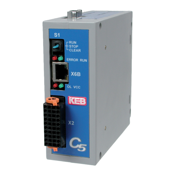
COMBICONTROL The operating unit View Front Name Function Addition View from the bottom Multi function switch/button Run-LED green ERROR ERROR-LED Overload Voltage supply (US) green Serial interface COMBIVIS Ethernet interface COMBIVIS/ CoDeSys Ethernet interface X1A…D Axis interfaces Serial interface (X6A) The socket X6A is a serial RS232/485 interface. -
Page 15: Ethernet Interface (X6B/X6C)
COMBICONTROL Ethernet interface (X6B/X6C) The standardized 10/100 base-T interface supports the protocols TCP/IP and UDP/IP. The two interfaces are internally connected as switch. The following ports have these functions: The CoDeSys port is adjusted to 1200 (as standard). The port can be changed with para- meter Et.03. -
Page 16: Multi-Function Switch/Button S1
COMBICONTROL Multi-function switch/button S1 The multi function switch/button is constructed as follows: run (switch) stop/reset clear (button) The button S1 is assigned with the following functions Activity Function Stop --> Run Program is started Run --> Stop Programm is stopped, all variables are resetted (reset warm) Stop -->... -
Page 17: Software
The axis control is programmed with the programming system CoDeSys of the company 3S- Software (www.3s-software.com). This programming software is free-available in the Internet. A KEB target information file (TNF) for the control is available as accessories, which contains all required hardware specifications. A library with firmware functional modules is further con- tained for access to the periphery (axes, real-time clock, switch, LED, file system). -
Page 18: Parameter Description
COMBICONTROL Parameter description 3.3.1 Runtime and error monitoring The ru-parameters serve for monitoring of the program flow. ru.00 Status Address 0200h Program status no prog no program loaded prog OK program loaded prog corrupt program checksum error Control status Program runs Stop Program stopped breakpoint... -
Page 19: Ethernet Parameter
COMBICONTROL 3.3.2 Ethernet parameter The following parameters contain the values, which are needed for the communication via the Ethernet interface. et.00 MAC address Address 0300h The MAC address (Media Access Control) is formed of 6 byte. The first three bytes contain the manufacturer's code (00-08-FA). -
Page 20: Real-Time Clock
COMBICONTROL data port password et.09 Address 0309h This parameter defines the write protection password for the COMBIVIS data port. The programming of the password occurs only via the serial interface. Then this password must be entered here again for write access via the data port. Error message "operation not possible"... -
Page 21: Process Image
COMBICONTROL seconds rc.01 Address 0401h This parameter displays the seconds in a range of 0...59. Writing on this parameter ad- justs the seconds. date rc.02 Address 0402h This parameter displays the date in a DD-MM format. Writing on this parameter adjusts the date. -
Page 22: Userdefinition Parameter
COMBICONTROL pi.07 axis outdata 3 Address 0507h Displays the value of the third process-output data (16 Bit) of the axes. Set 0 is for the data of axis 1, set 1 for the axis 2, etc. pi.08 fieldbus indata Address 0508h Displays the value of the Fieldbus-input data. -
Page 23: System Parameter
COMBICONTROL ud.06 error counters tx Address 0806h This parameter counts the errors during the transmission to each individual axis. Set 0 displays the errors of axis 1, set 1 of axis 2 etc. ud.07 fieldbus comm axis Address 0807h This parameter displays the axis, on which the field bus accesses to by parameter com- munication. -
Page 24: Debugging
This parameter determines the Fieldbus address. sy.07 baud rate 66019II Address 0007h The baud rate for the KEB DIN 66019II protocol is adjusted with this parameter. sy.10 Address 000Ah Display of the unit type. The following parameters serve for the operation of the inverter scope part of COMBIVIS. -
Page 25: System Variables
COMBICONTROL System variables The following system variables are available in the PLC program: SYSAXISMODE Displays the axes control mode adjusted via the function block 'tSetModes'. SYSERRORAXIS Displays the failed monitored or cyclic/synchronous operated axes. In case of failure of an axis the red error LED at the operating unit is switched on and the event "excpt_axis_error"... - Page 26 Notes GB - 26...
- Page 27 Notes GB - 27...
- Page 28 +39 02 33535311 • fax: +39 02 33500790 net: www.keb.it • mail: kebitalia@keb.it KEB Power Transmission Technology (Shanghai) Co.,Ltd. No. 435 QianPu Road, Songjiang East Industrial Zone, KEB Japan Ltd. CHN-201611 Shanghai, P.R. China 15–16, 2–Chome, Takanawa Minato-ku fon: +86 21 37746688 • fax: +86 21 37746600 J–Tokyo 108-0074...
Need help?
Do you have a question about the COMBICONTROL C5 and is the answer not in the manual?
Questions and answers