KEB C6 Instructions For Use Manual
Hide thumbs
Also See for C6:
- Instruction manual (100 pages) ,
- Instructions for use manual (84 pages) ,
- Instructions for use manual (66 pages)
Table of Contents
Advertisement
Quick Links
Advertisement
Table of Contents

Related Manuals for KEB C6


Summary of Contents for KEB C6
- Page 1 ROUTER INSTRUCTION FOR USE | C6 ROUTER Original Manual Document 20090747 EN 02...
-
Page 3: Preface
PREfaCE Preface The described hard- and software are developments of the KEB Automation KG. The enclosed documents correspond to conditions valid at printing. Misprint, mistakes and technical changes reserved. Signal words and symbols Certain operations can cause hazards during the installation, operation or thereafter. -
Page 4: Laws And Guidelines
If applicable, the license terms of this software are contained in the instructions for use. The instructions for use are already available to you, can be downloaded free of charge from the KEB website or can be requested from the respec- tive KEB contact person. -
Page 5: Table Of Contents
2.6 Right side C6 Router L1-L4 ......................27 2.7 Left side C6 Router L1-L4 ......................27 2.8 Rear side C6 Router L1-L4 ......................28 2.9 Rear side C6 Router E1-ET, E2-ET and E1-E4 ................28 2.10 Labels ............................29 2.11 antenna............................31 2.11.1 Pentaband stilo antenna .................... - Page 6 TabLE Of CONTENTS 3.2 Checking the package contents ....................33 3.3 Checking the operating conditions ..................... 33 3.4 Installation position ........................33 3.5 Damage due to overheating ......................34 3.6 Preparing the mounting ........................ 34 3.7 Mounting the device ........................34 3.7.1 Installation procedure wall mounting ..................
- Page 7 TabLE Of CONTENTS 6.5 Dimension drawings ........................62 6.5.1 C6 Router E1-E4 ........................ 62 6.5.2 C6 Router L1-L4 ......................... 63 6.5.3 Panel antenna drawing dimensions ................... 64 6.5.4 Wall mount antenna drawing dimensions ................65 6.5.5 Outdoor panel antenna drawing dimensions ..............66 6.6 Ports PINOUT ..........................
-
Page 8: List Of Figures
Figure 9: C6 Router L1-L4 left side ....................27 Figure 10: C6 Router L1-L4 rear side ....................28 Figure 11: C6 Router E1-ET, E2-ET and E1-E4 ................28 Figure 12: C6 Router labels ......................29 Figure 13: C6 Router labels ......................30 Figure 14: C6 Router SIM card sticker .................... - Page 9 LIST Of fIGURES Figure 44: COMBIVIS connect Router E2/L2 models ............... 51 Figure 45: COMBIVIS connect Router E2/L2 models ............... 51 Figure 46: COMBIVIS connect Router E2/L2 models ............... 52 Figure 47: Backup battery replacement .................... 53 Figure 48: Backup battery replacement .................... 53 Figure 49: Backup battery replacement ....................
-
Page 10: List Of Tables
LIST Of TabLES List of Tables Table 1: System software characteristics ..................57 Table 2: System hardware characteristics ..................58 Table 3: Electrical characteristics ....................58 Table 4: Mechanical characteristics ....................58 Table 5: Environmental characteristics ..................58 Table 6: Panel antenna characteristics .................. -
Page 11: Glossary
GLOSSaRy Glossary Earth-potential-free common point KEB productThe KEB product is subject of this manual. 1-phase mains KEB-I/O Small control system from the KEB-I/O 3-phase mains EtherCAT system AC current or voltage Application The application is the intended use of KEB-I/O I/O module family the KEB product. -
Page 12: Standards For Control & Automation
STaNDaRDS fOR CONTROL & aUTOMaTION Standards for control & automation DGUV regulation 3 Electrical installations and equipment DIN 46228-1 Wire-end ferrules; Tube without plastic sleeve DIN 46228-4 Wire-end ferrules; Tube with plastic sleeve DIN IEC 60364-5-54 Low-voltage electrical installations - Part 5-54: Selection and erection of electrical equipment - Earthing arrangements, protective conductors and protec- tive bonding conductors (IEC 64/1610/CD) DIN VDE 0100-729... - Page 13 STaNDaRDS fOR CONTROL & aUTOMaTION techniques - Surge immunity test (IEC 61000-4-5); German version EN 61000-4-5 EN 61000-4-6 Electromagnetic compatibility (EMC) - Part 4-6: Testing and measurement techniques - Immunity to conducted disturbances, induced by radio-frequency fields (IEC 61000-4-6); German version EN 61000-4-6 EN 61000-4-34 Electromagnetic compatibility (EMC) - Part 4-34: Testing and measurement techniques - Voltage dips, short interruptions and voltage variations immunity tests for equipment with mains current more than 16 A per phase (IEC 61000-4- 34);...
-
Page 14: Basic Safety Instructions
► Read the instructions for use ! ► Observe the safety and warning instructions ! ► If anything is unclear, please contact KEB Automation KG ! 1.1 Target Group This manual is written for design, project planning, servicing and commissioning ex- perts. Qualified personnel for the purpose of this instruction manual must have the fol-... -
Page 15: Transport, Storage And Proper Use
baSIC SafETy INSTRUCTIONS 1.2 Transport, storage and proper use The transport is carried out by qualified persons in accordance with the environmental conditions specified in this manual. The devices shall be protected against excessive strains. Electronic devices contain electrostatic sensitive components. ► Avoid contact. ► Wear ESD-protective clothing. Do not store the devices • in the environment of aggressive and/or conductive liquids or gases. •... -
Page 16: Electrical Connection
baSIC SafETy INSTRUCTIONS 1.4 Electrical connection In order to prevent malfunctions or unpredictable conditions, ob- ATTENTION serve the following instructions: ► For any work on the device switch off the supply voltage. ► Never bridge upstream protective devices (also not for test purpo- ses). ► Install all required covers and protective devices for operation. ►... -
Page 17: Repair
► Infringement will annul the liability for resulting consequences. 1.7 Disposal Electronic devices of the KEB Automation KG are exclusively professional devices for further industrial processing (so-called B2B devices). Manufacturers of B2B devices are obliged to take back and recycle devices manufac- tured after 14.08.2018. -
Page 18: System Description
Runtime concepts. 2.1 Special features • KEB COMBIVIS connect Router runtime on Microsoft Windows Embedded Com- pact 7. • Full compatibility with standard COMBIVIS connect software functions (see COM- BIVIS connect Control Center online manual for further information). -
Page 19: Router Package
SySTEM DESCRIPTION 2.2 Router package COMBIVIS connect Router device package consists of: E/L system DIN mount kit Wall mount kit n.1 Power supply plug n.1 Isolated IO plug Pentaband Stilo Antenna (optional) -
Page 20: Figure 1: Router Package
SySTEM DESCRIPTION Pentaband Outdoor An- tenna (optional) Pentaband Wall mount Antenna (optional) Antenna cable extension 3/5 m (optional) Figure 1: Router package... -
Page 21: Front View C6 Router E1 - E4
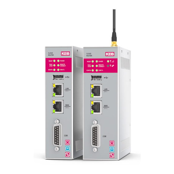
SySTEM DESCRIPTION 2.3 front view C6 Router E1 - E4 Reset LED (yellow) Run /Stop LED (green/red) COM Rx LED WAN ETH2 LAN ETH1 COM Tx LED (green) Remote connection LED (green) Power LED (green) Figure 2: Front detail The following behaviors are defined: •... -
Page 22: Figure 3: C6 Router E1-E4 Front View
USB stick data format not correct or unknown error blinks Active when at least one Control Center client Remote Steady lighted is connected to the C6 ROUTER E1, other- Connection wise off These LEDs are directly connected to the COM Rx Signal presence... -
Page 23: Front View C6 Router L1-L4
SySTEM DESCRIPTION 2.4 front view C6 Router L1-L4 Reset LED (yellow) Run /Stop LED (green/red) COM Rx LED WAN ETH2 LAN ETH1 COM Tx LED (green) 3G/4G modem activity 3G/4G modem connection RF antenna connector Remote Connection LED (green) Power LED (green) - Page 24 USB stick data format not correct or unknown error blinks Active when at least one Control Center client Remote Steady lighted is connected to the C6 ROUTER E1, other- connection wise off These LEDs are directly connected to the COM Rx Signal presence...
-
Page 25: Close-Up View C6 Router L1-L4
Modem currently connected. MODEM Modem disconnected. activity Figure 5: C6 Router L1-L4 front view 2.5 Close-up view C6 Router L1-L4 Reset key Button for restoring factory settings DC power input Digital input / output Antenna connection (only for L1-L4) Figure 6:... -
Page 26: Figure 7: C6 Router L1-L4 Features
It is required that COMBIVIS connect is successfully authen- ticated to the Domain. The output is active when at least one Control Center client OUT1 is connected to the COMBIVIS connect Router device. Figure 7: C6 Router L1-L4 features... -
Page 27: Right Side C6 Router L1-L4
SySTEM DESCRIPTION 2.6 Right side C6 Router L1-L4 Full stainless steel enclosure Aeration holes Figure 8: C6 Router L1-L4 right side 2.7 Left side C6 Router L1-L4 Full stainless steel enclosure Aeration holes Figure 9: C6 Router L1-L4 left side... -
Page 28: Rear Side C6 Router L1-L4
DIN book mounting hook holes SIM card socket Figure 10: C6 Router L1-L4 rear side 2.9 Rear side C6 Router E1-ET, E2-ET and E1-E4 Wall book mounting plate holes DIN book mounting hook holes Figure 11: C6 Router E1-ET, E2-ET and E1-E4... -
Page 29: Labels
SySTEM DESCRIPTION 2.10 Labels On the side panels there are the following labels: WAN MAC code LAN MAC code IMEI Mat.No. LAN IP 192.168.0.1 Mask 255.255.255.0 WAN IP DHCP User admin Password admin Figure 12: C6 Router labels... -
Page 30: Figure 13: C6 Router Labels
SySTEM DESCRIPTION DC input Digital input / output Electrical information COM interface Button for restoring factory settings Reset button Figure 13: C6 Router labels SIM card sticker Figure 14: C6 Router SIM card sticker... -
Page 31: Antenna
SySTEM DESCRIPTION 2.11 antenna 2.11.1 Pentaband stilo antenna • C6 Router direct mounting or panel mounting with extension cable • 20 W • 0dBi • 50 Ohm • 48 mm • SMA-M Figure 15: C6 Router Pentaband stilo antenna features... -
Page 32: Pentaband Outdoor Antenna
3 m cable • Wall mounting with 90° bracket • IP 67 • 50 W • 2.5dBi • 50 Ohm • 248 mm • SMA-M Figure 19: C6 Router Pentaband stilo antenna features Figure 20: C6 Router Pentaband wall mounting antenna... -
Page 33: Installation And Connection
Check the package content for visible signs of transport damage and for complete- ness. • In the case of damaged parts, contact your KEB representative. Do not install parts that were damaged during the shipment. 3.3 Checking the operating conditions •... -
Page 34: Damage Due To Overheating
The operating temperature must range between -20° and +70°C for E1-ET, E2-ET devices. • An inclined installation reduces the thermal convection of the device and the maxi- mum permissible ambient temperature for operation. Please contact KEB for details. • The device may otherwise be damaged and its certifications and warranty will be void. -
Page 35: Figure 23: Wall Mounting Procedure / Din Rail Mounting
INSTaLLaTION aND CONNECTION • Drill the required holes on the housing panel according to the instructions detailed in the figure. • There are 2 fastening points. Fastening can be made using stainless steel screws M4x20. Figure 23: Wall mounting procedure / DIN rail mounting •... -
Page 36: Figure 24: Wall Mounting Procedure / Din Rail Mounting
INSTaLLaTION aND CONNECTION Step 3: Release the top to match the slots with the screws. Step 4: Tighten the two screws. Figure 24: Wall mounting procedure / DIN rail mounting... -
Page 37: Wall Mounting Procedure Din Rail Mounting
INSTaLLaTION aND CONNECTION 3.7.2 Wall mounting procedure DIN rail mounting The system can be installed on a DIN guide as follows: • Mount the DIN hooks as shown. Figure 25: Wall mounting procedure / DIN rail mounting • Mount the DIN mounting rail into the system. -
Page 38: Figure 26: Wall Mounting Procedure / Din Rail Mounting
INSTaLLaTION aND CONNECTION • Example of correct installation. Figure 26: Wall mounting procedure / DIN rail mounting To remove the system from the DIN guide: • Lift the system up and release it from the DIN mounting rail. Figure 27: Wall mounting procedure... -
Page 39: Sim Installation
INSTaLLaTION aND CONNECTION 3.8 SIM installation The SIM card is not provided with the product.The SIM card must be associated with a data traffic plan. The traffic plan must be properly chosen depending on foreseen traffic generated by the remote assistance sessions and SMS notification usage (for L1-L4 models). The SIM card must be of ID-000 (ISO/IEC 7810) standard format (25 mm × 15 mm). Step 1: Insert the SIM card into the device. -
Page 40: Figure 28: Sim Installation
INSTaLLaTION aND CONNECTION Step 2: Pull the SIM card in the hole till you listen a “click”. Figure 28: SIM installation... -
Page 41: Antenna Installation
INSTaLLaTION aND CONNECTION 3.9 antenna Installation 3.9.1 Pentaband stilo antenna The exact dimensions for this are in the chapter "Technical specifications / dimension drawings". • Drill a 6.5 mm hole in the metal. • Recommended torque for mounting is 0.9 Nm. Figure 29: Pentaband stilo antenna... -
Page 42: Pentaband Wall Mounting Antenna
INSTaLLaTION aND CONNECTION 3.9.2 Pentaband wall mounting antenna The exact dimensions for this are in the chapter "Technical specifications / dimension drawings". Figure 30: Pentaband wall mounting antenna 3.9.3 Pentaband outdoor antenna The exact dimensions for this are in the chapter "Technical specifications / dimension drawings". • Drill a 13.0 mm hole in the metal. • Recommended torque for mounting is 2.94 Nm. • Maximum torque for mounting is 3.92 Nm. -
Page 43: Connecting The Device
INSTaLLaTION aND CONNECTION 3.10 Connecting the device 3.10.1 Notes on connection • COMBIVIS connect Router device must be installed in accordance with the indi- cations contained in this instruction manual. • These devices are intended to be connected to a “Secondary Circuit Overvoltage Category II”. -
Page 44: Connecting The Ethernet Ports
INSTaLLaTION aND CONNECTION Figure 32: Connections for the power supply 3.10.4 Connecting the Ethernet ports The routers always have two Ethernet ports, one is referred as WAN (Internet connec- tion), the other one as LAN (automation network). Figure 33: Connections for the Ethernet ports When using the cable connection for Internet, it must be connected to the WAN port.The LAN port shall be connected to the automation sub-network. -
Page 45: Connecting The Serial Port
A special DB15 connector supports all serial protocols (pin assignment see chapter 6.4.1). Therefore it is necessary to adapt the connections to the technical requirements; KEB can supply connector adapters as optional parts but user can adapt DB15 connec- tor by himself.For further details please contact KEB. -
Page 46: Figure 36: Adapter Cable
The line connection and polarization is normally realized by using resistors mounted internally to the standard Profibus / MPI connectors. The KEB adapter cable provides on the DB9-F connection side all signals required by the MPI communication and the line connection.The KEB cable converter does NOT contain resistors for line termination.Present notes do not replace the official documen- tation about Profibus and MPI network wiring. Please refer to official specification for any... -
Page 47: Connecting The Digital Inputs And Outputs (I/O)
INSTaLLaTION aND CONNECTION 3.12 Connecting the digital inputs and outputs (I/O) This section shows some examples of how to connect the digital inputs and outputs (I/O) with key switches, buttons and lamps. 3.12.1 IN0 - WaN connection enabling security key Figure 38: IN0-WAN connection example for activating a security key 3.12.2 IN1–Reset input... -
Page 48: Out0-Wan Connection To Activate Signalling Equipment
INSTaLLaTION aND CONNECTION 3.12.3 OUT0-WaN connection to activate signalling equipment Figure 40: OUT0-WAN to activate signalling equipment Figure 41: OUT0-WAN to activate signalling equipment... -
Page 49: Out0 - Remote Assistance Service Running
INSTaLLaTION aND CONNECTION 3.12.4 OUT0 – Remote assistance service running Figure 42: OUT0-Remote services application Figure 43: OUT0-Remote services application... -
Page 50: Commissioning
COMBIVIS connect Router device requires for the configuration COMBIVIS connect Control Center version 2 or above. Control Center is available for download in the dedi- cated product section of the www.keb.de website. 4.1.1 COMbIVIS connect Router E2/L2 models COMBIVIS connect Router devices with data monitoring functionality (E2/L2 models) can be additionally configured to run a COMBIVIS HMI project for data collection, alarm notification and web visualization. These models come out from production already con-... -
Page 51: Figure 44: Combivis Connect Router E2/L2 Models
COMMISSIONING Figure 44: COMBIVIS connect Router E2/L2 models The following window will appear: Figure 45: COMBIVIS connect Router E2/L2 models Select "TCP" in the upper left list. Write the IP address of the Router (WAN or LAN port IP) Under "Upload Device Path", select the download path in which the project is to be saved in the router. -
Page 52: Figure 46: Combivis Connect Router E2/L2 Models
COMMISSIONING To transfer the project click on the button “Upload Project”. Once the transfer is complet- ed, click “Start Device Project” to run the application. the name of the memory are according to the following table: Name used by the user Memory Note system... -
Page 53: Maintenance
MaINTENaNCE 5 Maintenance 5.1 Maintaining and cleaning COMBIVIS connect Router device is designed for maintenance-free operation except for the replacing of the battery backup when necessary. NOTICE Notice: Do not use detergents, solvents, cleaners or objects that could scratch the surface. NOTICE Notice: switch off the power before any cleaning operation. -
Page 54: Figure 49: Backup Battery Replacement
MaINTENaNCE Remove the screw as indicated in the figure. Figure 49: Backup battery replacement Locate the battery position. Figure 50: Backup battery replacement Remove the battery. -
Page 55: Backup And Restore
COMBIVIS connect Router device. For more information please see the COMBIVIS connect Control Center online manual or contact the KEB support center. 5.4 Update of the operating system COMBIVIS connect Router device is a hardware device that works thanks to a set of... -
Page 56: Technical Support And Repairs
KEB offers wide-ranging, complete after-sales technical support. The staff who deal with this handle questions on the entire range of products skillfully, quickly, and efficiently. You can phone our staff in the service department, and they will give you complete, prompt advice on how to resolve your problems. KEB Automation KG Suedstrasse 38 32683 Barntrup, Germany telephone +49 5263 401-0 Fax +49 5263 401-116... -
Page 57: Technical Specifications
Ethernet interfaces Type 1 x 10/100Mbps WAN (RJ45) with link/activity leds 1 x 100Mbps LAN (RJ45) with link/activity leds 3G/4G modem (only for C6 Rout- Type provides data service under global GSM/GPRS/EDGE/ er L1-L4) WCDMA networks (14.4Mbps Downlink data rate) -
Page 58: Table 2: System Hardware Characteristics
Electrical characteristics Mechanical characteristics Housing Type Book mount Material Steel, white galvanized Table 4: Mechanical characteristics Environmental characteristics Temperature C6 Router Operation 0° … +50°C E1-E4 / L1-L4 Storage -20° … +60°C Temperature C6 Operation 0° … +70°C E1ET, E2ET Storage -20°... -
Page 59: Panel Antenna Characteristics
TECHNICaL SPECIfICaTIONS 6.2 Panel antenna characteristics Electrical Frequency range 800MHz to 2200MHz Bands GSM-DCS-PCS-UMTS-CDMA-GPRS-EDGE-HSPA VSWR ≤ 2.3 Polarization Linear Power handling 20 W Impedance 50 Ohm Connector Straight SMA(M) Table 6: Panel antenna characteristics Environmental & mechanical Temperature -40° to +85°C Radome color black Radome material... -
Page 60: Wall Mount Panel Antenna Characteristics
TECHNICaL SPECIfICaTIONS 6.3 Wall mount Panel antenna characteristics Mains form Frequency (MHz) 824 ~ 896 880 ~ 960 1710 ~ 1880 1850 ~ 1990 1710 ~ 2170 Peak gain (dbi) Free space -0.7 -0.9 L-angle bracket average gain (dbi) Free space -5.7 -5.3 -2.2... -
Page 61: Outdoor Panel Antenna Characteristics
TECHNICaL SPECIfICaTIONS 6.4 Outdoor Panel antenna characteristics Electrical Antenna Standard 2G/3G/4G Operation frequency (MHz) 698~960 MHz 1710~2170 MHz 2500~2800MHz Peak Gain 1.2 dBi 3.2dBi 2.5dBi Average gain -4.5 dB -2.5 dB -4.5 dB Efficiency VSWR <3.0:1 Impedance 50Ω Polarization Linear Radiation properties Omni-directional Input power... -
Page 62: Dimension Drawings
TECHNICaL SPECIfICaTIONS 6.5 Dimension drawings 6.5.1 C6 Router E1-E4 Figure 53: Dimensions... -
Page 63: C6 Router L1-L4
TECHNICaL SPECIfICaTIONS 6.5.2 C6 Router L1-L4 Figure 54: Dimensions... -
Page 64: Panel Antenna Drawing Dimensions
TECHNICaL SPECIfICaTIONS 6.5.3 Panel antenna drawing dimensions Figure 55: Panel antenna drawing dimensions... -
Page 65: Wall Mount Antenna Drawing Dimensions
TECHNICaL SPECIfICaTIONS 6.5.4 Wall mount antenna drawing dimensions Figure 56: Wall mount antenna drawing dimensions... -
Page 66: Outdoor Panel Antenna Drawing Dimensions
TECHNICaL SPECIfICaTIONS 6.5.5 Outdoor panel antenna drawing dimensions Figure 57: Outdoor panel antenna drawing dimensions 6.6 Ports PINOUT 6.6.1 COM1 – Db15M serial Signal Isolated +5 VDC Transmit data (RS-232) Receive data (RS-232) Request to send Clear to send... -
Page 67: Digital Input / Output
TECHNICaL SPECIfICaTIONS Data set ready Isolated ground Data terminal ready Carrier detect Transmit data + / receive data + (RS-485/RS-422) Transmit data - / receive data - (RS-485/RS-422) Ring indication (RS-232) Receive data + (RS-422) Receive data - (RS-422) N.C. Table 10: COM - DB15M serial Any polarization or termination resistor connected to RS422/485 channel, if... -
Page 68: Certification
CERTIfICaTION 7 Certification 7.1 Mark of conformity Document No. / month.year: ce_ca_RED-C6F-Router-b_en / 02.2021 Manufacturer: KEB Automation KG Südstraße 38 32683 BARNTRUP Germany C6fD Product type: Control type xx – xxxx Control size yy = 00 x = any letter or number... - Page 69 1: General requirements EN 61010-2-201 Version 2013 Safety requirements for electrical equipment for measurement, control and laboratory use – Part 2-201: Particular requirements for control equipment KEB Automation KG, Südstr. 38, D-32683 Barntrup www.keb.de E-Mail: info@keb.de Tel.: +49 5263 401-0...
- Page 70 Zertifizierungsstelle des RWTÜV Steubenstrasse 53 D - 45138 Essen No. of approval 041 004 500 Dated: 20.10.1994 Valid until: December 2021 KEB Automation KG, Südstr. 38, D-32683 Barntrup www.keb.de E-Mail: info@keb.de Tel.: +49 5263 401-0 Fax: -116 page: 3 of 3...
-
Page 71: Ul Marking
CERTIfICaTION 7.2 UL Marking... - Page 72 NOTES...
- Page 73 Tel: +33 149620101 Fax: +33 145767495 c / Mitjer, Nave 8 - Pol. Ind. LA MASIA E-Mail: info@keb.fr Internet: www.keb.fr 08798 Sant Cugat Sesgarrigues (Barcelona) Spain Tel: +34 93 8970268 Fax: +34 93 8992035 E-Mail: vb.espana@keb.de Germany Geared Motors KEB Antriebstechnik GmbH...
- Page 74 Automation with Drive www.keb.de KEB Automation KG Suedstrasse 38 32683 Barntrup Tel. +49 5263 401-0 E-Mail: info@keb.de...
Need help?
Do you have a question about the C6 and is the answer not in the manual?
Questions and answers