
Related Manuals for KEB F6 Series


Summary of Contents for KEB F6 Series
- Page 1 F6 ELEVATOR DRIVE INSTRUCTIONS FOR USE | INSTALLATION F6 OPERATOR WITH GRAPHIC USER INTERFACE Translation of the original manual Document 20379757 US 00...
-
Page 3: Preface
The hardware, software, accessories in this document are products of KEB America, Inc. The information contained in this document is valid at the time of publishing. KEB reserves the right to update this document in response to misprints, mistakes, or tech- nical changes. -
Page 4: More Symbols
Laws and guidelines KEB Automation KG confirms with the EC declaration of conformity and the CE mark on the device nameplate that it complies with the essential safety requirements. The EC declaration of conformity can be downloaded on demand via our website. -
Page 5: Support
The customer may use the instructions for use as well as further documents or parts from it for internal purposes. Copyrights are with KEB and remain valid in its entirety. This KEB product or parts thereof may contain third-party software, including free and/ or open source software. -
Page 6: Table Of Contents
TAbLE OF cONTENTS Table of contents Preface ..............................3 Signal words and symbols ......................3 More symbols ..........................4 Laws and guidelines ........................4 Warranty and liability ........................4 Support 5 Copyright ............................5 Table of contents ........................... 6 List of Figures ............................8 List of Tables ............................ - Page 7 TAbLE OF cONTENTS 6.2 Operator main menu ........................21 6.2.1 Switching on ........................21 6.2.2 Required files ........................21 6.3 Non-changeable parameters ......................23 6.4 changeable parameters ........................ 24 6.4.1 Changing with "Up“ and "Down“ ..................24 6.4.2 Selection of subindices ....................... 25 6.4.3 Numeric input ........................26 6.5 Abbreviations in the function toolbar ..................
-
Page 8: List Of Figures
Figure 6: Remove the blind Cover .........................18 Figure 7: Attach the operator .........................19 Figure 8: Control elements ..........................20 Figure 9: KEB lift home screen ........................21 Figure 10: Main menu ............................21 Figure 11: Non-changeable parameters ......................23 Figure 12: Changeable parameters .......................24 Figure 13: Selection of subindices .........................25... -
Page 9: List Of Tables
LIST OF TAbLES List of Tables Table 1: Order data ............................13 Table 2: Revision levels of the housings ......................15 Table 3: Operator files............................22 Table 4: Abbreviations in the function toolbar ....................26... -
Page 10: Basic Safety Instructions
The following safety instructions have been created by KEB America, Inc. for elevator drive technology. These instructions can be supplemented by local, country- or applica- tion-specific safety instructions where relevant. -
Page 11: Electrical Connection
bASIc SAFETy INSTRUcTIONS 1.3 Electrical connection Voltage at the terminals and in the device! DANGER Danger to life due to electric shock! ► For any work on the unit switch off the supply voltage and secure it against switching on. ►... -
Page 12: Product Description
The semiconductors and components used in KEB products are developed and de- signed for use in industrial products. Restriction The product is not permitted to be used in vital life-sustaining applications, i.e. medical, without the expressed written consent of KEB Automation KG or KEB America Inc. gen- eral management. -
Page 13: Residual Risks
PRODUcT DEScRIPTION 2.1.1 Residual risks Despite intended use, the drive converter can reach unexpected operating conditions in case of error, with wrong parameterization, by faulty connection or non-professional interventions and repairs. These can be: • Wrong direction of rotation • Motor speed too high •... -
Page 14: Description Of The Operator
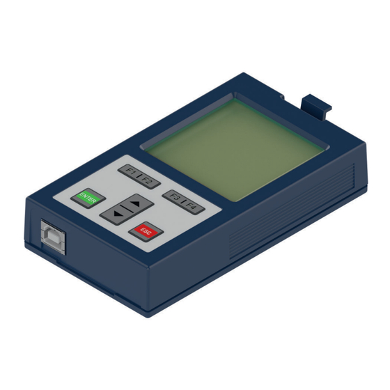
DEScRIPTION OF THE OPERATOR 3 Description of the operator Front view Rear view bottom view Legend Locking lever Nameplate LC display 160 x 160 pixel, 32 levels of grey Version without interface Control panel Version with USB interface (USB-B) X6A: Interface to the drive controller Version with Ethernet interface Figure 1: Description of the operator... -
Page 15: Control Card Block Incl. Operator
The error is reset by switching the 24 V voltage of the drive controller off and on again. This behaviour can occur for devices of the F6 series with housing 6, 7, 8 and 9. From the revision levels listed in the table, an operator can be plugged in without regard to the operating state. -
Page 16: Interfaces
INTERFAcES 4 Interfaces 4.1 Operator interface The interface fulfills the following functions: • Communication with the F6 device (protocol DIN 66019 II) • Voltage supply of the operator A combined RS485 interface is used as interface, which is provided as 9-pole D-Sub plug connector. -
Page 17: Diagnostic Interfaces
INTERFAcES 4.2 Diagnostic interfaces 4.2.1 Ethernet interface Figure 4: Ethernet interface The ethernet interface emulates the diagnostic interface on the F6 device. DIN 66019 II is used as protocol via TCP or UDP on port 8000 and KebFtp on port 8002. Additionally, it can be accessed to parameters / objects of the operator. -
Page 18: Assembly Of The Operator
ASSEMbLy OF THE OPERATOR 5 Assembly of the operator Assembly of the operator on a F6 housing 2: 1. Loosen the blind cover by pressing the locking lever and remove it. Figure 6: Remove the blind Cover 2. Attach the F6 operator at the lower edge and tilt it into the cutout. -
Page 19: Figure 7: Attach The Operator
ASSEMbLy OF THE OPERATOR 3. Engage the locking lever. Figure 7: Attach the operator... -
Page 20: Navigation
NAVIGATION 6 Navigation 6.1 control elements Name Function Menu bar Inverter parameter Function bar ① Operator parameter Function key 1 Parameter saving Function key 2 Up/Download Function key 3 Work list Function key 4 File operations • Scroll menu bar to top FTP mode Enter test mode •... -
Page 21: Operator Main Menu
The operator responds to all node addresses but will add the node of the connected drive controller. The KEB Lift Home screen is the first screen displayed upon booting the operator. The Home screen will always display six modules and emulates the KEB F5 Home screen. -
Page 22: Table 3: Operator Files
The information required for correct operation is normally read out automatically from the drive controller by the operator. If any of the files listed are missing for any reason, please contact KEB. For independent installation of the files => FTP mode. -
Page 23: Non-Changeable Parameters
NAVIGATION 6.3 Non-changeable parameters The parameter groups are dependent on the drive controller type. ▲ Fb Fieldbus OS04 Language Fl Flash File System [ ] Deutsch Db Debugging OS05 Contrast ENTER [ ] 14 → OS06 Font size ← [ ] 2.13 pixel OS07 Backlight mode [ ] Auto OS08 Software date... -
Page 24: Changeable Parameters
NAVIGATION 6.4 changeable parameters 6.4.1 changing with "Up“ and "Down“ ▲ OS03 Startup mode [ ] 0 OS04 Language [ ] German _ OS05 Contrast [ ] 14 OS06 Font size [ ] 2:13 pixel OS07 Backlight mode [ ] Auto ▼... -
Page 25: Selection Of Subindices
NAVIGATION 6.4.2 Selection of subindices dr00 motor type [ ] 0: asynchron. motor (ASM) _ dr01 motor part number Selection of a parameter [C] 101 with subindices dr02 motordata state [ ] 00h dr03 rated current recognizable by [C] [ ] 1A (C = Count) dr04 rated speed [ ] 0.000 1/min... -
Page 26: Numeric Input
NAVIGATION 6.4.3 Numeric input OS08 2182h OS08 2182h dr01 2201h set:1 dr01 2201h set:1 Software date Software date motor part number motor part number → 2016.0323 2016.0323 ← ← DecHex < - DecHex DecHex >> ENTER Round up to the next valid value ↓... -
Page 27: Inverter Parameters
NAVIGATION 6.6 Inverter parameters The menu item inverter parameter includes all available drive controller parameters on the control board. They are func- tion-related divided into groups. They are displayed on the Inverter parameter operator via the internal bus. Operator parameter For the display of the drive controller parameters, the opera- Parameter saving tor requires the appropriate configuration file, which must be... -
Page 28: Operator Parameters
NAVIGATION 6.7 Operator parameters The operator parameters display the parameter groups of the operator. Select the operator parameter with the keys ▲ and ▼ and con- Inverter parameter firm with ENTER. Operator parameter Parameter saving Up/Download Work list File operations FTP mode Enter test mode Figure 16: Operator parameters... -
Page 29: Operator System Parameters (Os)
NAVIGATION 6.7.1 Operator system parameters (OS) Only the meanings of the parameter values are described in the following. Value range, data length and data type; Access mode and the default values can be taken from COM- BIVIS. OS00 Operator type Parameter address 0x0180 Value... - Page 30 NAVIGATION OS04 Language Parameter address 0x2384 Value Description Use the keys ▲ and ▼ to choose one of the following languages: 0…7 • 0: English • 1: German • 2: American • 3: Francais • 4: Italiano • 5: Russian •...
- Page 31 NAVIGATION OS09 Software date Parameter address 0x2182 Value Description 0.0000… Software date of the operator. 9999.1231 Display of the year before the point, month and day behind. 2014.0513 equals 13.05.2014. OS10 Software version Parameter address 0x2184 Value Description Displays the software version of the operator. OS11 Serial number Parameter address...
-
Page 32: Fieldbus Parameters (Fb)
NAVIGATION 6.7.2 Fieldbus parameters (Fb) Fb00 MAC address Parameter address 0x2280 Value Description The MAC address (Media Access Control) is formed of 6 bytes. Only the lowest 4 bytes are displayed at "FAxxxxxx“. This address is assigned by the manufacturer and cannot be changed. -
Page 33: Debugging Parameters (Db)
NAVIGATION Fb10 DHCP server Parameter address 0x228A Value Description Serves for switching off and on of the DHCP server functionality. 0…1 BootP- and DHCP requests are answered delayed in activated state. The following restrictions become valid because the operator has no information about available IP addresses in the network: The DHCP server is only provided for operation with cross/patch cable to a PC/note- book, in order to assign an IP address to the PC/notebook if neccessary. -
Page 34: Flash File System Parameters (Fi)
NAVIGATION 6.7.4 Flash file system parameters (FI) FI00 Max. bytes Parameter address 0x2480 Value Description Displays the maximum number of possible bytes. Max. files FI01 Parameter address 0x2481 Value Description Displays the maximum number of possible files. FI02 Used bytes Parameter address 0x2482 Value... -
Page 35: Customer Interface Parameters (Ci)
NAVIGATION 6.7.5 customer interface parameters (ci) ci00 Screen Layout Parameter Address 0x3080 Value Description Stores the display settings for each Diagnostic screen. ci01 GUI Main Screen Parameter Address 0x3081 Value Description 1...2147483647 Stores the parameter addresses for display. ci02 GUI Screen 1 Parameter Address 0x3082 Value... - Page 36 NAVIGATION ci11 GUI Screen 10 Parameter Address 0x308b Value Description 1...2147483647 Stores the parameter addresses for display.
-
Page 37: Parameter Saving
NAVIGATION 6.8 Parameter saving ENTER opens the submenu for parameter saving. Parameter saving (Upload) = F3 Inverter parameter Operator parameter All inverter and operator parameters are read and saved in the Parameter saving flash memory. Every new upload process overwrites the pre- Up/Download saved parameter lists. -
Page 38: Work List
NAVIGATION 6.10 Work list ENTER opens the submenu for the worklist. The selection of a work list of the flash memory occurs in this Inverter parameter Operator parameter menu item. Parameter saving Up/Download Parameter lists, created with COMBIVIS in .wr5 format can be Work list transmitted via ftp to the operator. -
Page 39: Ftp Mode
File operations FTP mode Enter test mode Figure 22: FTP mode One of the programs ‘KEB FTP’ or ‘COMBIVIS’ is required to install missing files. Each file can be protected with an access level ( File operations). 6.13 Function test of keyboard and display ENTER starts a test mode, to check the function of the single keys and the LC-display. -
Page 40: Screen Overview
F6 operator GUI screens. 7.1 Home and diagnostic screens The KEB Lift Home screen will always display six modules and emulates the KEB F5 Home screen. From the home screen, function key F1 can be used to return to the last viewed diagnostic screen. -
Page 41: Figure 26: Parameter View Screen
ScREEN OVERVIEW saved through the Default Options menu. If changed through Combivis, the ‘Customer_ LIFT.dw5’ (or ‘Customer_drive.dw5’) file must be saved and transferred to the operator. The updated view will now remain after rebooting. The six display formats are: • Scrolling Text (TxT): The operator will display the variable name and the data as a text string that will scroll if needed. -
Page 42: Fault Log Screen
ScREEN OVERVIEW 7.2 Fault log screen The final diagnostic screen is a fault log which pulls entries from the inverter and dis- plays up to five faults on the screen at once. The fault log will display the timestamp and error code of the faults that the inverter con- tains. -
Page 43: Password Screen
ScREEN OVERVIEW The drive inverter parameters can be accessed from the File menu screen. If the invert- er ‘.blb’ file is missing from the operator, the user can upload it from the ‘configuration missing’ screen. The ‘F’ function keys will navigate as follows: Function bar Description Home Return to Home screen... -
Page 44: File Menu Screen
ScREEN OVERVIEW Function bar Description Prog Return to Home screen <- Remove digits Test Go to Test screen Engage arrow functions >> Add digits Digit value scroll up Digit value scroll down Figure 31: Setup screen 7.7 File menu screen The File Menu screen displays a list of options depending upon the password level of the inverter. -
Page 45: Ftp Mode Screen
ScREEN OVERVIEW Function bar Description Menu Return to the File Menu Go to FTP menu Delete selected file Delete Figure 33: File operations screen 7.9 FTP mode screen From the File Operations screen, the FTP screen connects the operator with a computer to transfer files. -
Page 46: Upload/Download Screen
ScREEN OVERVIEW 7.11 Upload/Download screen On the Upload/Download screen, a user can write a set of parameter values to the drive control or copy the current drive control parameters to the operator. In order to use the Upload or Download functions, a user needs to have an existing dw5 file for the config ID they want to interact with. -
Page 47: Default Options Screen
ScREEN OVERVIEW 7.12 Default options screen The default options screen has two menu options for either generating a new default file or manually defaulting the operator’s display from an existing default file. The first menu option progresses to the manual default screen where a user can select a default file to update the operator display. -
Page 48: Selecting A New Parameter To Display On The Graphic User Interface (Gui)
ScREEN OVERVIEW 7.13 Selecting a new parameter to display on the graphic user interface (GUI) Updating the selected parameter can be completed through the operator and simplified for multiple parameters. Updating the displayed parameter using the procedure below will automatically set the address, sub-index, and length correctly within the Ci parameters. -
Page 49: Figure 38: Parameter Select Screens
ScREEN OVERVIEW 4. Navigate to the desired parameter and press F1 (‘Select’ function) to display the parameter in the selected position. 5. The screen is updated and now displays the parameter in the selected position. Figure 38: Parameter select screens Adjusting the screen using this procedure will update the non-volatile memory, saving the parameters through boot, but does not automatically update the default file. -
Page 50: Screen Navigation
ScREEN OVERVIEW 7.14 Screen navigation The diagrams in this section dispay the sequential flow of F6 operator screens when navigating the graphic user interface (GUI). Figure 39: Operator screen navigation diagram... -
Page 51: Figure 40: Diagnostic Screen Navigation Diagram
ScREEN OVERVIEW Figure 40: Diagnostic screen navigation diagram... -
Page 52: Revision History
REVISION HISTORy 8 Revision history Version Date Description 2024-04 Initial Release... -
Page 53: Notes
NOTES Notes... - Page 54 NOTES...
- Page 55 / Mitjer, Nave 8 - Pol. Ind. LA MASIA E-Mail: info@keb.cz Internet: www.keb.cz 08798 Sant Cugat Sesgarrigues (Barcelona) Spain Tel: +34 93 8970268 Fax: +34 93 8992035 E-Mail: vb.espana@keb.de France Société Française KEB SASU Z.I. de la Croix St. Nicolas 14, rue Gustave Eiffel...
- Page 56 Automation with Drive www.kebamerica.com KEB America, Inc. 5100 Industrial Blvd. S. Shakopee, MN 55379 Tel. +1 952 2241400 E-Mail: info@kebamerica.com...
Need help?
Do you have a question about the F6 Series and is the answer not in the manual?
Questions and answers