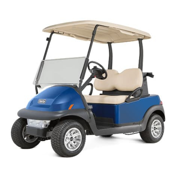
Club Car Precedent Maintenance And Service Manual

Electric vehicle with eric charging system gasoline vehicle with kohler ech440 engine
Hide thumbs Also See for Precedent:
Table of Contents

Advertisement

Quick Links

2020 Precedent,
Villager 2 and 4
Maintenance and
Service Manual
Electric Vehicle with ERIC Charging System
Gasoline Vehicle with Kohler ECH440 Engine
Manual Number 86753090004
Edition Code B

Advertisement

Table of Contents
loading

Summary of Contents for Club Car Precedent

  • Page 1 2020 Precedent, Villager 2 and 4 Maintenance and Service Manual Electric Vehicle with ERIC Charging System Gasoline Vehicle with Kohler ECH440 Engine Manual Number 86753090004 Edition Code B...
  • Page 3 To find your local authorized Club Car dealer, visit www.clubcardealer.com, call 1-800-ClubCar (1-800-258-2227), or scan this Quick Response (QR) code to be taken to the Club Car dealer locator. Refer to Figure 1. Download a QR code reader such as RedLaser or Barcode Scanner to your cell phone or tablet.
  • Page 4 NOTE: This manual represents the most current information at the time of publication. Club Car is continually working to further improve its vehicles and other products. These improvements may affect servicing procedures.
  • Page 5 Serial Number Decal 2843B Figure -1 Serial Number Decal © Copyright 2019 Club Car, LLC Club Car is a registered trademark of Club Car, LLC This manual effective October, 2019 2020 Precedent,Villager 2 and 4 Maintenance and Service Manual Page iii...
  • Page 7: Table Of Contents

    Seat Hinge Removal ..........................4-4 Seat Hinge Installation ..........................4-4 Hip Restraint ..............................4-5 Hip Restraint Removal ..........................4-5 Hip Restraint Installation ..........................4-5 Front Body ..............................4-5 Front Body Removal ..........................4-5 2020 Precedent,Villager 2 and 4 Maintenance and Service Manual Page v...
  • Page 8 Fixed Rear Seat ............................4-45 Fold-Down Rear Seat ..........................4-48 Seat Support ............................4-52 Foot Deck - 2+2............................4-53 Rear Beauty Panel (2+2 Vehicles) ......................4-57 Rear UnderBody............................4-58 Page vi 2020 Precedent,Villager 2 and 4 Maintenance and Service Manual...
  • Page 9 Front Shock Absorber Installation ......................7-20 Front Wheel Hubs............................7-22 Front Wheel Free Play Inspection ......................7-22 Front Wheel Hub Removal ........................7-22 Front Wheel Hub Installation ........................7-23 2020 Precedent,Villager 2 and 4 Maintenance and Service Manual Page vii...
  • Page 10 Quick Reference Guide – Excel with ERIC Charging System................11-4 System Info ..............................11-5 Model Number............................11-5 Serial Number ............................11-5 Hardware Version .............................11-5 Protocol Version ............................11-5 Param Block Version..........................11-5 MFG Date Code ............................11-5 OS Version...............................11-5 Page viii 2020 Precedent,Villager 2 and 4 Maintenance and Service Manual...
  • Page 11 High Speed WalkAway..........................11-20 Speed sensor ............................11-20 Main Driver On ............................11-20 Main Coil Open............................11-20 Main Dropout (1 or 2)..........................11-21 Motor Stall.............................. 11-21 Main Driver Off ............................11-21 2020 Precedent,Villager 2 and 4 Maintenance and Service Manual Page ix...
  • Page 12 Motor Controller Output Regulator (MCOR) ....................13-8 Testing the MCOR ........................... 13-8 MCOR Removal ............................13-8 MCOR Installation ........................... 13-8 Reverse Buzzer............................13-9 Testing the Reverse Buzzer........................13-9 Reverse Buzzer Removal......................... 13-9 Page x 2020 Precedent,Villager 2 and 4 Maintenance and Service Manual...
  • Page 13 External Charger Status Indicators......................15-4 Onboard Charger Status Indicators......................15-5 Long-term Storage........................... 15-6 External Charger Mounting........................... 15-7 AC Power Connection..........................15-8 The Charge Circuit............................15-9 Charger Operation ............................15-10 Charging Batteries ..........................15-10 2020 Precedent,Villager 2 and 4 Maintenance and Service Manual Page xi...
  • Page 14 Transaxle Installation ..........................17-10 SECTION 18 — Gasoline Vehicle - Troubleshooting and Electrical System............18-1 General Information ............................. 18-1 Accessories............................. 18-1 Features of the Electronic Fuel Injection (EFI) System ................18-1 Page xii 2020 Precedent,Villager 2 and 4 Maintenance and Service Manual...
  • Page 15 Multi-Purpose Buzzer Limit Switch Installation ..................19-25 Neutral Lockout Limit Switch ........................19-25 Neutral Lockout Limit Switch Removal .....................19-25 Neutral Lockout Limit Switch Installation....................19-26 Transaxle Limit Switch ..........................19-27 Transaxle Limit Switch Removal ......................19-27 2020 Precedent,Villager 2 and 4 Maintenance and Service Manual Page xiii...
  • Page 16 To Relieve Fuel Pressure ........................21-11 Carbon Canister ............................21-12 Carbon Canister Removal ........................21-12 Carbon Canister Installation ........................21-12 Fuel Line..............................21-13 Fuel Line Removal..........................21-13 Fuel Line Installation ..........................21-15 Fuel Pump Module............................21-17 Page xiv 2020 Precedent,Villager 2 and 4 Maintenance and Service Manual...
  • Page 17 Rear Wheel Bearing Installation........................ 24-7 Axle Shaft Oil Seal Removal........................24-7 Axle Shaft Oil Seal Installation ........................24-8 Transaxle Removal ............................24-9 Transaxle Installation ..........................24-12 Forward/Neutral/Reverse Handle.........................24-13 Forward/Neutral/Reverse Handle Removal....................24-13 2020 Precedent,Villager 2 and 4 Maintenance and Service Manual Page xv...
  • Page 18 SECTION 25 — Kohler Engine Service Manual ....................25-1 SECTION 26 — Wiring Diagrams........................26-1 General Information ............................. 26-1 Engine Harness Wiring Diagram Table ......................26-2 Index ................................Index-1 Page xvi 2020 Precedent,Villager 2 and 4 Maintenance and Service Manual...
  • Page 19: Section 1 - Safety

    • A CAUTION with the safety alert symbol indicates a hazard or unsafe practice that could result in minor personal injury. CAUTION • A CAUTION without the safety alert symbol indicates a potentially hazardous situation that could result in property damage. 2020 Precedent,Villager 2 and 4 Maintenance and Service Manual Page 1-1...
  • Page 20: General Warnings

    • The vehicle will not provide protection from lightning, flying objects, or other storm-related hazards. If caught in a storm while driving a Club Car vehicle, exit the vehicle and seek shelter in accordance with applicable safety guidelines for your location.
  • Page 21: Disabling The Vehicle

    DISCONNECT THE BATTERY - GASOLINE VEHICLES Disable the vehicle. Disconnect the negative (-) cable (1) (Figure 1-1, Page 1-3). Figure 1-1 Gasoline Vehicle Battery Disconnect the positive (+) cable (2). 2020 Precedent,Villager 2 and 4 Maintenance and Service Manual Page 1-3...
  • Page 22: Connect The Battery - Gasoline Vehicles

    Disconnect the negative (-) cable (1) (Figure 1-2, Page 1-4). Figure 1-2 Disconnect Electric Vehicle Batteries Disconnect the positive (+) cable (2). Wait 90 seconds for the controller capacitors to discharge. Page 1-4 2020 Precedent,Villager 2 and 4 Maintenance and Service Manual...
  • Page 23: Connect The Batteries - Electric Vehicles

    Figure 1-3 Connect Electric Vehicle Batteries Connect the negative (-) cable (1). Tighten the hardware to 110 lb·in (12.4 N·m). Apply battery terminal protector spray to the battery terminals. 2020 Precedent,Villager 2 and 4 Maintenance and Service Manual Page 1-5...
  • Page 24: Recycling Lead-Acid Batteries

    Responsibility for environmental protection must be shared, not only by the manufacturers of the batteries, but by people who use the batteries as well. Please contact your nearest Club Car dealer or distributor for information on how to properly recycle your batteries. 1403...
  • Page 25: Section 2 - Vehicle Specifications

    ELECTRIC MOTOR DESCRIPTION 2 PASSENGER VILLAGER 2 VILLAGER 4 Motor Type: 48V DC motor ● ● ● Motor Horsepower: 3.1 hp (2.3 kW) ● ● ● 2020 Precedent,Villager 2 and 4 Maintenance and Service Manual Page 2-1...
  • Page 26: Batteries

    1409 lb (639.1 kg) 1409 lb (639.1 kg) 1824 lb (827.4 kg) Maximum Gross Vehicle Combination Weight 1409 lb (639.1 kg) 1409 lb (639.1 kg) 1824 lb (827.4 kg) Page 2-2 2020 Precedent,Villager 2 and 4 Maintenance and Service Manual...
  • Page 27: Gasoline - Vehicle Specifications

    Cargo Capacity The cargo capacity includes the weight of optional equipment. Maximum Towing The maximum towing weight is the maximum weight the vehicle can tow with a Club Car approved tow kit. Weight Trailer Tongue Weight The trailer tongue weight is the maximum permitted weight applied by the trailer tongue onto the trailer hitch.
  • Page 28: Performance

    0.8 (m/s²)² (± 0.25) 0.8 (m/s²)² (± 0.25) 0.8 (m/s²)² (± 0.23) EN 13059:2002 TRANSAXLE DESCRIPTION 2 PASSENGER VILLAGER 2 VILLAGER 4 Fluid Capacity: 67.6 fl-oz (2 l) ● ● ● Page 2-4 2020 Precedent,Villager 2 and 4 Maintenance and Service Manual...
  • Page 29: Vehicle Weights And Load Capacities

    Cargo Capacity The cargo capacity includes the weight of optional equipment. Maximum Towing The maximum towing weight is the maximum weight the vehicle can tow with a Club Car approved tow kit. Weight Trailer Tongue Weight The trailer tongue weight is the maximum permitted weight applied by the trailer tongue onto the trailer hitch.
  • Page 30 Gasoline - Vehicle Specifications VEHICLE SPECIFICATIONS Pagination Page Page 2-6 2020 Precedent,Villager 2 and 4 Maintenance and Service Manual...
  • Page 31: Section 3 - Extended Storage

    NOTE: It takes approximately five charge cycles with a minimum of 10-amp hours of use after each charge to correctly mix the water with battery acid. Turn off all electronic accessories. 2020 Precedent,Villager 2 and 4 Maintenance and Service Manual Page 3-1...
  • Page 32: Return To Service From Extended Storage - Electric

    If the batteries were disconnected, connect the batteries. Fully charge the batteries. Set the Run/Tow switch to RUN. Set the Forward/Neutral/Reverse control (FNR) to N. Adjust the pressure in each tire to the recommended tire pressure. Page 3-2 2020 Precedent,Villager 2 and 4 Maintenance and Service Manual...
  • Page 33 EXTENDED STORAGE Electric Vehicle Extended Storage Have a trained technician lubricate the vehicle. Do a daily pre-operation safety checklist. Do a vehicle performance inspection. 2020 Precedent,Villager 2 and 4 Maintenance and Service Manual Page 3-3...
  • Page 34: Gasoline Vehicle Extended Storage

    Plug the fuel tank vent nipple with a slip-on vinyl cap (1) (Figure 3-1, Page 3-4). Make sure that the connection is air tight. Figure 3-1 Fuel Tank Vent Nipple Disconnect the battery. Clean the battery. Page 3-4 2020 Precedent,Villager 2 and 4 Maintenance and Service Manual...
  • Page 35: Return To Service From Extended Storage - Gasoline

    RETURN TO SERVICE FROM EXTENDED STORAGE - GASOLINE Clean the battery. Connect the fuel system: 2.1. Remove and discard the slip-on vinyl cap (1) from the fuel tank vent nipple (Figure 3-3, Page 3-6). 2020 Precedent,Villager 2 and 4 Maintenance and Service Manual Page 3-5...
  • Page 36 Adjust the pressure in each tire to the recommended tire pressure. Have a trained technician lubricate the vehicle. Do a daily pre-operation safety checklist. Do a vehicle performance inspection. Page 3-6 2020 Precedent,Villager 2 and 4 Maintenance and Service Manual...
  • Page 37: Section 4 - Body And Trim

    Use non-abrasive wax products. Do not use abrasive leveling or rubbing compounds; these will permanently dull the gloss. Fertilizers, tars, asphalt, creosote, paint, or chewing gum should be removed immediately to prevent possible stains. NOTE: Dispose of waste water properly. 2020 Precedent,Villager 2 and 4 Maintenance and Service Manual Page 4-1...
  • Page 38: Cleaning The Vehicle Interior

    Hold a heat gun 12 inches (30 cm) away from the affected area, with the gun on its lowest heat setting. Periodically remove the heat gun and bend the body, using a push block, in the opposite direction of the deformation. Page 4-2 2020 Precedent,Villager 2 and 4 Maintenance and Service Manual...
  • Page 39: Minor Scratches And Surface Blemishes

    GOUGES, PUNCTURES, TEARS, LARGE SCRATCHES, AND ABRASIONS Touch-up is not recommended. Replace the entire body part or have it repaired by a professional paint and body ® repair shop with experience repairing Surlyn bodies. 2020 Precedent,Villager 2 and 4 Maintenance and Service Manual Page 4-3...
  • Page 40: Seat Hinge

    Remove the hinge (3). SEAT HINGE INSTALLATION Align the hinge (3) onto the seat bottom (1) (Figure 4-1). Install the screws (2). Tighten the screws to 75 lb·in (8.5 N·m). Page 4-4 2020 Precedent,Villager 2 and 4 Maintenance and Service Manual...
  • Page 41: Hip Restraint

    See General Warnings on page 1-2. FRONT BODY REMOVAL Remove the four screws (2) and pull the brow cap (1) from the brow and fascia assembly (4) (Figure 4-3, Page 4-7). 2020 Precedent,Villager 2 and 4 Maintenance and Service Manual Page 4-5...
  • Page 42: Front Body Installation

    Position brow cap (1) to cover the edge of both the brow (5) and the front beauty panel (3). Secure brow cap (1) with four screws (2). Tighten screws to 25 in·lb (2.8 N·m). Page 4-6 2020 Precedent,Villager 2 and 4 Maintenance and Service Manual...
  • Page 43 BODY AND TRIM Front Body Figure 4-3 Front Body 2020 Precedent,Villager 2 and 4 Maintenance and Service Manual Page 4-7...
  • Page 44: Front Bumper

    The front bumper (3) is attached to the vehicle frame rails by nuts (5) and bolts (4). The nuts are tightened to 13.3 ft·lb (18 N·m). Figure 4-4 Bracket and Front Bumper Page 4-8 2020 Precedent,Villager 2 and 4 Maintenance and Service Manual...
  • Page 45: Headlight Adjustment

    Tighten screws to 66 in·lb (7.5 N·m). While it is possible to add washers with the headlight/bumper assembly mounted to the vehicle, these adjustments may be easier if the headlight/front bumper assembly is unbolted first (Figure 4-5, Page 4-9). Figure 4-5 Headlight Aiming 2020 Precedent,Villager 2 and 4 Maintenance and Service Manual Page 4-9...
  • Page 46: Instrument Panel

    Make sure that electrical wires are not exposed or pinched. Install the screws (1). Tighten the screws to 22 lb·in (2.5 N·m). Page 4-10 2020 Precedent,Villager 2 and 4 Maintenance and Service Manual...
  • Page 47: Dash Assembly

    Put the dash assembly (3) on vehicle (Figure 4-7). Make sure tabs on the forward edge engage to front underbody. Connect the USB receptacle. Install the screws (2). Tighten the screws to 8.8 lb·ft (12 N·m). Install the instrument panel (1). 2020 Precedent,Villager 2 and 4 Maintenance and Service Manual Page 4-11...
  • Page 48: Floor Mat And Retainers

    Make sure that the floor mat (3) is correctly positioned beneath the top flange of the floor mat retainer. Install the two screws (2). Do not tighten the screws. Page 4-12 2020 Precedent,Villager 2 and 4 Maintenance and Service Manual...
  • Page 49 BODY AND TRIM Floor Mat and Retainers Install the push rivets (4) (Figure 4-8, Page 4-12). Tighten the two screws (2) to 4.4 lb·ft (6.0 N·m). 2020 Precedent,Villager 2 and 4 Maintenance and Service Manual Page 4-13...
  • Page 50: Kick Plate And Charger Receptacle Bezel - Electric Vehicles

    Use the charger bezel tool to remove charger receptacle bezel (1) from the kick plate (2) (Figure 4-9, Page 4-14). Remove the floor mat. Remove three screws (3) and washers (4). Remove the two front screws (5). Page 4-14 2020 Precedent,Villager 2 and 4 Maintenance and Service Manual...
  • Page 51: Kick Plate And Charger Receptacle Bezel Installation

    Install the three screws (1) and washers (2). Tighten the screws to 3.3 lb·ft (4.5 N·m). Install the two front screws (5). Tighten screws to 3.7 lb·ft (5 N·m). Install the floor mat. Install the charger receptacle bezel (4). 2020 Precedent,Villager 2 and 4 Maintenance and Service Manual Page 4-15...
  • Page 52: Kick Plate - Gasoline Vehicles

    Install the three screws (1) and washers (2). Tighten the screws to 3.3 lb·ft (4.5 N·m). Install two front screws (4). Tighten the screws to 3.7 lb·ft (5 N·m). Install the floor mat. Page 4-16 2020 Precedent,Villager 2 and 4 Maintenance and Service Manual...
  • Page 53: Access Panel

    Remove the two push rivets (1) (Figure 4-12). Remove the access panel (2). ACCESS PANEL INSTALLATION Install the access panel (2) onto the rear underbody (Figure 4-12). Install the two push rivets (1). 2020 Precedent,Villager 2 and 4 Maintenance and Service Manual Page 4-17...
  • Page 54: Visage Display Unit Overhead Baskets

    Align the overhead basket (3) with the display unit support (Figure 4-13, Page 4-18). Push the overhead basket forward until the tab (2) locks. Install the screw (1). Tighten the screw to 17.7 lb·in (2.0 N·m). Page 4-18 2020 Precedent,Villager 2 and 4 Maintenance and Service Manual...
  • Page 55: Overhead Speaker Basket Removal

    Align the overhead speaker basket (3) with the display unit support. Push the overhead speaker basket forward until the tab (2) locks. Install the screw (1). Tighten the screw to 17.7 lb·in (2.0 N·m). 2020 Precedent,Villager 2 and 4 Maintenance and Service Manual Page 4-19...
  • Page 56: Two-Passenger - Canopy

    Remove the nuts (1), washer (2), and bolts (3) from the canopy (4) and each front canopy strut (Figure 4-15). Remove the nuts (6), washer (7), and bolts (8) from the canopy and each rear canopy support. Remove the canopy. Page 4-20 2020 Precedent,Villager 2 and 4 Maintenance and Service Manual...
  • Page 57: Two-Passenger Canopy Installation

    Remove the overhead baskets. See Display Unit Overhead Basket. Remove the nuts (1), washers (2), and bolts (3) from each front canopy strut (Figure 4-17, Page 4-22). 2020 Precedent,Villager 2 and 4 Maintenance and Service Manual Page 4-21...
  • Page 58 Figure 4-18 Visage Display Unit Removal Remove the Visage display unit (VDU) (10) from the display unit support. Disconnect the display unit harness (11). Remove the display unit support (12). Page 4-22 2020 Precedent,Villager 2 and 4 Maintenance and Service Manual...
  • Page 59: Two-Passenger Canopy With Visage Display Unit Installation

    Install the Visage display unit (VDU) (10) onto the display unit support. Install the screws (9). Tighten the screws to 24 lb·in (2.7 N·m). Make sure that the strut harness is routed correctly. 2020 Precedent,Villager 2 and 4 Maintenance and Service Manual Page 4-23...
  • Page 60 Install the bolts (3), washers (2), and nuts (1). Tighten the hardware to 50 lb·in (5.6 N·m). Install the bolts (6), washers (5), and nuts (4). Tighten the hardware to 50 lb·in (5.6 N·m). Install the overhead baskets. See Display Unit Overhead Basket. Page 4-24 2020 Precedent,Villager 2 and 4 Maintenance and Service Manual...
  • Page 61: Two-Passenger Front Canopy Strut Removal

    Remove the canopy. Remove the screw (1) (Figure 4-21). Slide the front canopy strut cover (2) up the front canopy strut (3). Remove the screws (4) and the front canopy strut. 2020 Precedent,Villager 2 and 4 Maintenance and Service Manual Page 4-25...
  • Page 62: Two-Passenger Front Canopy Strut Installation

    Install the front canopy strut cover (2) onto the front canopy strut. Install the screws (4). Tighten the screws to 18.4 lb·ft (25 N·m). Install the screw (1). Tighten the screw to 31 lb·in (4.6 N·m). Install the canopy. Page 4-26 2020 Precedent,Villager 2 and 4 Maintenance and Service Manual...
  • Page 63: Two-Passenger Rear Canopy Support Removal

    This could result in damage to the components. Figure 4-23 Rear Canopy Support Removal Remove the canopy. Remove the screw (1) (Figure 4-23). Remove the rear canopy support (2). 2020 Precedent,Villager 2 and 4 Maintenance and Service Manual Page 4-27...
  • Page 64: Two-Passenger Rear Canopy Support Installation

    These serve as common attachment points for various accessories. Accessories that can be mounted on the SAM include single or dual sand bottles, sand bucket, and the club cleaner. Page 4-28 2020 Precedent,Villager 2 and 4 Maintenance and Service Manual...
  • Page 65: Structural Accessory Module (Sam)

    Remove the four bolts (1). SAM Installation Position the SAM (2) over its mounting holes (Figure 4-25). Install the four screws (1). Tighten the screws to 71 lb·in (8 N·m). 2020 Precedent,Villager 2 and 4 Maintenance and Service Manual Page 4-29...
  • Page 66: Seat Back

    Remove the seat back (2) from the SAM (3). Seat Back Installation Put the seat back (2) on the SAM (3) (Figure 4-26). Install the two screws (1). Tighten the screws to 51 lb·in (5.8 N·m). Page 4-30 2020 Precedent,Villager 2 and 4 Maintenance and Service Manual...
  • Page 67: Bag Rack Assembly

    Remove the bag rack (2) from the SAM (3). Bag Rack Installation Install the bag rack (2) onto the SAM (3) (Figure 4-27). Install the two screws (1). Tighten the screws to 53 lb·in (6 N·m). 2020 Precedent,Villager 2 and 4 Maintenance and Service Manual Page 4-31...
  • Page 68: Bag Strap

    Bag Strap Installation Install the bag strap (3) onto the bag rack (4) (Figure 4-28). Install the push rivets (1) and screw (2). Tighten the screw to 31 lb·in (3.5 N·m). Page 4-32 2020 Precedent,Villager 2 and 4 Maintenance and Service Manual...
  • Page 69: Sweater Basket

    Remove the sweater basket (2) from the bag rack (3). Sweater Basket Installation Install the sweater basket (2) onto the bag rack (3) (Figure 4-29). Install the three screws (1). Tighten the screws to 31 lb·in (3.5 N·m). 2020 Precedent,Villager 2 and 4 Maintenance and Service Manual Page 4-33...
  • Page 70: Rear Beauty Panel

    Install the Forward / Neutral / Reverse control (FNR). Put the canopy support brackets (2) on the vehicle. Install the screw (1). Tighten the screw to 53 lb·in (6 N·m). Page 4-34 2020 Precedent,Villager 2 and 4 Maintenance and Service Manual...
  • Page 71: Rear Underbody

    Remove the rear underbody from the vehicle. Rear Underbody Installation Install the rear underbody (2) onto the vehicle (Figure 4-31). Install the four screws (1). Tighten the screws to 71 lb·in (8 N·m). 2020 Precedent,Villager 2 and 4 Maintenance and Service Manual Page 4-35...
  • Page 72: Rear Crossmember

    Install the rear crossmember (2) onto the vehicle (Figure 4-32). Make sure that the J-clips (3) are installed on the inside of the frame rail. Install the four bolts (1). Tighten the bolts to 56 lb·in (6.35 N·m). Page 4-36 2020 Precedent,Villager 2 and 4 Maintenance and Service Manual...
  • Page 73: Villager 4 - Monsoon Canopy

    Remove the nuts (1), washers (2), and bolts (3) from the front canopy strut (4) (Figure 4-33). Figure 4-33 Canopy Removal - Front Canopy Strut Remove the screws (5) (Figure 4-34). Remove the canopy (6). Figure 4-34 Canopy Removal - Rear Canopy Support 2020 Precedent,Villager 2 and 4 Maintenance and Service Manual Page 4-37...
  • Page 74: Monsoon Canopy Installation

    Install the bolts (3), washers (2), and nuts (1) to secure the front canopy strut (4) (Figure 4-36). Tighten the hardware to 80 lb·in (9 N·m). Figure 4-36 Canopy Installation - Front Canopy Strut Page 4-38 2020 Precedent,Villager 2 and 4 Maintenance and Service Manual...
  • Page 75: 2+2 Front Canopy Strut Removal

    Remove the canopy. Remove the screw (1) (Figure 4-37). Slide the front canopy strut cover (2) up the front canopy strut (3). Remove the screws (4) and the front canopy strut. 2020 Precedent,Villager 2 and 4 Maintenance and Service Manual Page 4-39...
  • Page 76: 2+2 Front Canopy Strut Installation

    Install the front canopy strut cover (2) onto the front canopy strut. Install the screws (4). Tighten the screws to 18.4 lb·ft (25 N·m). Install the screw (1). Tighten the screw to 31 lb·in (4.6 N·m). Install the canopy. Page 4-40 2020 Precedent,Villager 2 and 4 Maintenance and Service Manual...
  • Page 77: 2+2 Rear Canopy Support Removal

    This could result in damage to the components. Figure 4-39 Rear Canopy Support Removal Remove the canopy. Remove the screws (1) and brackets (2) (Figure 4-39). Remove the rear canopy support (3). 2020 Precedent,Villager 2 and 4 Maintenance and Service Manual Page 4-41...
  • Page 78: 2+2 Rear Canopy Support Installation

    Install the rear canopy support (3) into the rear underbody (Figure 4-40). Install the brackets (2) onto the rear canopy support. Install the screws (1). Tighten the screws to 80 lb·in (9 N·m). Page 4-42 2020 Precedent,Villager 2 and 4 Maintenance and Service Manual...
  • Page 79: Villager 4 - Rear Body

    Remove the screws (1) from the front seat back (2) (Figure 4-41). Remove the front seat back. Remove the screws (3) from the rear seat back (4). Remove the rear seat back. 2020 Precedent,Villager 2 and 4 Maintenance and Service Manual Page 4-43...
  • Page 80 Install the rear seat back (5) onto the seat support (6). Make sure the seat support tab (7) is installed in the rear seat back. Install the screws (8). Tighten the screw to 4.4 lb·ft (6 N·m). Page 4-44 2020 Precedent,Villager 2 and 4 Maintenance and Service Manual...
  • Page 81: Fixed Rear Seat

    Install the rear seat bottom tabs into the seat supports. Lower the rear seat bottom (2) onto the seat supports (Figure 4-43). Install the screws (1). Tighten the screws to 4.4 lb·ft (6 N·m). 2020 Precedent,Villager 2 and 4 Maintenance and Service Manual Page 4-45...
  • Page 82 Remove the hinge (2). Fixed Rear Seat Hinge Installation Install the hinge (2) onto the rear seat bottom (Figure 4-44). Install the screws (1). Tighten the screws to 4.4 lb·ft (6 N·m). Page 4-46 2020 Precedent,Villager 2 and 4 Maintenance and Service Manual...
  • Page 83 Install the screws (3). Tighten the screws to 4.4 lb·ft (6 N·m) (Figure 4-45). Install the strut angle (2) on the rear hip restraint. Install the screws (1). Tighten the screws to 4.4 lb·ft (6 N·m). 2020 Precedent,Villager 2 and 4 Maintenance and Service Manual Page 4-47...
  • Page 84: Fold-Down Rear Seat

    Fold-Down Rear Seat Bottom Installation Put the rear seat bottom (2) onto the fold-down hinge (3) (Figure 4-46). Install the screws (1). Tighten the screws to 6.6 lb·ft (9 N·m). Page 4-48 2020 Precedent,Villager 2 and 4 Maintenance and Service Manual...
  • Page 85 Install the bolts (2) and nuts (3). Tighten the nuts to 13 lb·ft (17.5 N·m). Install the bolts (4), washers (5) and nuts (6). Tighten the bolts to 8.5 lb·ft (11.5 N·m). 2020 Precedent,Villager 2 and 4 Maintenance and Service Manual Page 4-49...
  • Page 86 Install the screws (3). Tighten the screws to 4.4 lb·ft (6 N·m). Install the strut angle (2) on the rear hip restraint. Install the screws (1). Tighten the screws to 4.4 lb·ft (6 N·m). Page 4-50 2020 Precedent,Villager 2 and 4 Maintenance and Service Manual...
  • Page 87 Install the nut (4) and bolt (5). Tighten the bolt to 8.5 lb·ft (11.5 N·m). Install the nut (1), washers (2), and bolt (3). Tighten the bolt to 8.5 lb·ft (11.5 N·m). 2020 Precedent,Villager 2 and 4 Maintenance and Service Manual Page 4-51...
  • Page 88: Seat Support

    Install the screw (2). Tighten the screw to 13 lb·ft (17.5 N·m). Install the screws (1). Tighten the screws to 7 lb·ft (10 N·m). Install the rear seat bottom assembly. Install the hip restraints. Install the seat backs. Page 4-52 2020 Precedent,Villager 2 and 4 Maintenance and Service Manual...
  • Page 89: Foot Deck - 2+2

    Foot Deck Removal Figure 4-51 Foot Deck (2+2) Removal Support the foot deck. Remove the screws (1) (Figure 4-51). Remove the screws (2). Remove the bolts (3) and the foot deck. 2020 Precedent,Villager 2 and 4 Maintenance and Service Manual Page 4-53...
  • Page 90 Remove the push rivets (1) (Figure 4-52). Remove the floormat (2). Remove the screws (3). Remove the foot deck (4). Remove the screws (5). Remove the handrail (6) from the foot deck support (7). Page 4-54 2020 Precedent,Villager 2 and 4 Maintenance and Service Manual...
  • Page 91 Install the foot deck (5) onto the foot deck support. Install the screws (6). Tighten the screws to 6 lb·ft (8 N·m). Install the floormat (7) onto the foot deck. Install the push rivets (8). 2020 Precedent,Villager 2 and 4 Maintenance and Service Manual Page 4-55...
  • Page 92 Install the bolts (3) (Figure 4-54). Tighten the bolts to 22 lb·ft (30 N·m). Install the screws (2). Tighten the screws to 13 lb·ft (18 N·m). Install the screws (1). Tighten the screws to 7 lb·ft (10 N·m). Page 4-56 2020 Precedent,Villager 2 and 4 Maintenance and Service Manual...
  • Page 93: Rear Beauty Panel (2+2 Vehicles)

    4-55). Install the screws (1). Tighten the screws to 44 lb·in (5 N·m). Install the FNR control. Install the rear seat assembly. Install the front seat bottom. 2020 Precedent,Villager 2 and 4 Maintenance and Service Manual Page 4-57...
  • Page 94: Rear Underbody

    Install the rear underbody (2) on the vehicle (Figure 4-56). Install the screws (1). Tighten the screws to 71 lb·in (8 N·m). Install the access panel. Install the rear beauty panel. Page 4-58 2020 Precedent,Villager 2 and 4 Maintenance and Service Manual...
  • Page 95: Section 5 - Accelerator And Brake Pedal Group

    Remove two screws (2) on the driver side of the pedal group and two screws (1) on the passenger side of the pedal group. Disconnect the wire harness (12) from the MCOR (13). Lift pedal group from vehicle. 2020 Precedent,Villager 2 and 4 Maintenance and Service Manual Page 5-1...
  • Page 96 Pedal Group – Electric Vehicle ACCELERATOR AND BRAKE PEDAL GROUP 2518 Figure 5-2 Pedal Group – Electric Vehicle Page 5-2 2020 Precedent,Villager 2 and 4 Maintenance and Service Manual...
  • Page 97: Mcor

    Install the floor mat (2) over the pedal group. Make sure tabs on floor mat sides are beneath the sill (3). Tighten screws (1) to 53 in·lb (6 N·m) (Figure 5-1, Page 5-1). Connect batteries. See Connect the Batteries – Electric Vehicles, Section 1, Page 1-5. 2020 Precedent,Villager 2 and 4 Maintenance and Service Manual Page 5-3...
  • Page 98: Pedal Group - Gasoline Vehicle

    Remove two screws (2) on the driver side of the pedal group and two screws (1) on the passenger side of the pedal group. Disconnect six-pin connector (12) from throttle position sensor. Release the end of the accelerator cable (13) from the pedal group. Lift pedal group from vehicle. Page 5-4 2020 Precedent,Villager 2 and 4 Maintenance and Service Manual...
  • Page 99: Throttle Position Sensor

    The throttle position sensor itself is not intended to be replaced. If sensor is determined to need replacing through test procedures found in this manual, the accelerator pedal assembly must be replaced. See Accelerator Pedal Removal on page 5-6. 2020 Precedent,Villager 2 and 4 Maintenance and Service Manual Page 5-5...
  • Page 100: Pedal Group Installation

    Insert accelerator pedal assembly (7) through bottom of pedal group mounting plate and secure with four screws (13) (Figure 5-5, Page 5-8). Tighten screws (13) to 38 in·lb (4.3 N·m). Install debris shields (4 and 5). Page 5-6 2020 Precedent,Villager 2 and 4 Maintenance and Service Manual...
  • Page 101: Brake Pedal Removal

    Tighten screws (12) to 100 in·lb (11.3 N·m). Install debris shields (4 and 5). Install pedal group in vehicle. See Pedal Group Installation on page 5-3. See Pedal Group Installation on page 5-6. 2020 Precedent,Villager 2 and 4 Maintenance and Service Manual Page 5-7...
  • Page 102 Brake Pedal Installation ACCELERATOR AND BRAKE PEDAL GROUP Figure 5-5 Accelerator Pedal Assembly and Brake Pedal Assembly Page 5-8 2020 Precedent,Villager 2 and 4 Maintenance and Service Manual...
  • Page 103: Section 6 - Wheel Brake Assemblies

    When not performing a test or service procedure that requires movement of the wheels, lock the brakes. Remove the floor mat. Remove the pedal access panel. 2020 Precedent,Villager 2 and 4 Maintenance and Service Manual Page 6-1...
  • Page 104 • The brake shoes are under pressure and can release suddenly when brake shoe retainers are removed. 1400-18100-10222B Figure 6-2 Remove Shoe Retainer Clip If the brake drums cannot be easily removed: Page 6-2 2020 Precedent,Villager 2 and 4 Maintenance and Service Manual...
  • Page 105: Brake Shoe Removal

    Figure 6-3 Shoe Retainer Pins Grasp both brake shoes and pull them, together with the springs, out of the brake assembly (Figure 6-4). 1400-17700-10225 Figure 6-4 Remove Brake Shoes 2020 Precedent,Villager 2 and 4 Maintenance and Service Manual Page 6-3...
  • Page 106 Brake Shoe Removal WHEEL BRAKE ASSEMBLIES Remove adjuster wheel (11) with two washers (12 and 13) from the backing plate (Figure 6-5). 2732B Figure 6-5 Remove Adjuster Wheel Page 6-4 2020 Precedent,Villager 2 and 4 Maintenance and Service Manual...
  • Page 107: Brake Assembly Cleaning

    Lubricate the slide (3) with dry moly lubricant (Figure 6-7). 2733B Figure 6-7 Lubricate Slide Make sure that the slide can easily move back and forth. Install the dust cover onto the backing plate. 2020 Precedent,Villager 2 and 4 Maintenance and Service Manual Page 6-5...
  • Page 108 (Figure 6-9). Figure 6-9 Apply Grease To Brake Shoes and Slots Page 6-6 2020 Precedent,Villager 2 and 4 Maintenance and Service Manual...
  • Page 109 Figure 6-10 Apply Grease To Brake Adjuster Install the adjuster wheel (5) and two washers (6 and 7) into the adjuster assembly (Figure 6-11). 2732C Figure 6-11 Install Adjuster Wheel 2020 Precedent,Villager 2 and 4 Maintenance and Service Manual Page 6-7...
  • Page 110: Brake Shoe Installation

    If the retainer pins (5) were sheared during removal, replace the retainer pins (Figure 6-13). Use pliers to compress and install the shoe retainer clip (6), while turning the retainer pin into position. 2737B Figure 6-13 Install Trailing Shoe Retainer Clip Page 6-8 2020 Precedent,Villager 2 and 4 Maintenance and Service Manual...
  • Page 111 Install the leading shoe (9) in the slots in the shoe mounting block (A) and the adjuster assembly (B) (Figure 6-15). 646B Figure 6-15 Install Leading Shoe Use pliers to compress and install the shoe retainer clip, while turning the retainer pin into position. 2020 Precedent,Villager 2 and 4 Maintenance and Service Manual Page 6-9...
  • Page 112 NOTE: If drum installation is difficult, the brake shoes may need to be adjusted vertically in the mounting slots. Make sure that the axle and drum turn freely. Install the wheels. Lower the rear of the vehicle. Page 6-10 2020 Precedent,Villager 2 and 4 Maintenance and Service Manual...
  • Page 113 Install the turnbuckle. Make sure that the brake cables (15) are installed in the brake equalizer (16). 636E Figure 6-18 Turnbuckle Installation Adjust the brake cable equalizer. Electric Vehicle: Connect the batteries. Gasoline Vehicle: Connect battery and spark plug wire. 2020 Precedent,Villager 2 and 4 Maintenance and Service Manual Page 6-11...
  • Page 114: Brake Cable Equalizer Adjustment

    If the measurement is 2 inches (±1/16) (51 mm (±1.6), the adjustment is complete. If the measurement is not 2 inches (±1/16) (51 mm (±1.6): 8.1. Repeat the adjustment procedure. Install the access panel. Install the floor mat. Page 6-12 2020 Precedent,Villager 2 and 4 Maintenance and Service Manual...
  • Page 115: Brake Cluster

    NOTE: When servicing vehicles with severely worn brake shoes and when the drums cannot be removed by normal methods, use the following steps to minimize damage to the brake cluster and brake components. 2020 Precedent,Villager 2 and 4 Maintenance and Service Manual Page 6-13...
  • Page 116 Electric Vehicle: Remove the axle shaft. Gasoline Vehicle: Remove the wheel hub assembly. Remove the brake shoes. Remove and discard the bow tie locking pin (9) (Figure 6-22). 2731C Figure 6-22 Brake Cluster Removal Page 6-14 2020 Precedent,Villager 2 and 4 Maintenance and Service Manual...
  • Page 117: Brake Cluster Installation

    Install new bolts (2) and lock nuts (3). Tighten the bolt heads to 30 lb·ft (40.6 N·m). Install the clevis pin (4). Install the new bow tie locking pin (5). 2020 Precedent,Villager 2 and 4 Maintenance and Service Manual Page 6-15...
  • Page 118 Lower the rear of the vehicle. Adjust the brake cable equalizer. Install the pedal access panel. Install the floor mat. Electric Vehicle: Connect the batteries. Gasoline Vehicle: Connect the battery and spark plug wire. Page 6-16 2020 Precedent,Villager 2 and 4 Maintenance and Service Manual...
  • Page 119: Brake Cable

    Remove the brake cables (6) from the equalizer bracket. 636C Figure 6-25 Remove Turnbuckle Remove the nut (7) (Figure 6-26). Do not remove bolt (8). Remove the mounting tab (9) of the brake cable from the bolt. 2020 Precedent,Villager 2 and 4 Maintenance and Service Manual Page 6-17...
  • Page 120 (Figure 6-27). 650D Figure 6-27 Retaining clips Remove and discard the bow tie locking pin (11) (Figure 6-28). Page 6-18 2020 Precedent,Villager 2 and 4 Maintenance and Service Manual...
  • Page 121 Use a brake cable release tool to compress the retaining clips on the end of the cable housing enough to slip the cable end out of the bracket (14) and remove the brake cable from the vehicle. 2020 Precedent,Villager 2 and 4 Maintenance and Service Manual Page 6-19...
  • Page 122: Brake Cable Installation

    Pivot the equalizer to the horizontal position to capture the cable heads in the equalizer. 636D Figure 6-30 Install Cables In Equalizer Bracket Page 6-20 2020 Precedent,Villager 2 and 4 Maintenance and Service Manual...
  • Page 123 Install the nut (8). Tighten the nut to 18.4 lb·ft (25 N·m). Adjust the brake cable equalizer. Electric Vehicle: Connect the batteries. Gasoline Vehicle: Connect the battery and spark plug wire. 2020 Precedent,Villager 2 and 4 Maintenance and Service Manual Page 6-21...
  • Page 124 Brake Cable WHEEL BRAKE ASSEMBLIES Pagination Page Page 6-22 2020 Precedent,Villager 2 and 4 Maintenance and Service Manual...
  • Page 125: Section 7 - Steering And Front Suspension

    Gasoline Vehicle: Disconnect battery and spark plug wire. Rotate steering wheel to a straight ahead position. CAUTION • Do not turn the steering until the steering wheel has been installed. Remove the screws (1) (Figure 7-1). 2020 Precedent,Villager 2 and 4 Maintenance and Service Manual Page 7-1...
  • Page 126: Steering Wheel Installation

    Remove the steering wheel from the steering column. STEERING WHEEL INSTALLATION Apply a small amount of oil or anti-seize compound to steering shaft (2) (Figure 7-3). Install the steering wheel (1) on the steering shaft. Page 7-2 2020 Precedent,Villager 2 and 4 Maintenance and Service Manual...
  • Page 127 Install steering wheel retaining bolt (3). Tighten the bolt to 37 lb·ft (50 N·m). Put the cover (4) on the steering wheel. Install the screws (5). Tighten the screws to 15 lb·in (1.7 N·m). 2020 Precedent,Villager 2 and 4 Maintenance and Service Manual Page 7-3...
  • Page 128: Steering Column

    Remove the dash insert, instrument panel, dash assembly, and front bumper. Remove the bolt (1) (Figure 7-4). Remove the bolts (2). Remove the steering column (3) from the vehicle. Page 7-4 2020 Precedent,Villager 2 and 4 Maintenance and Service Manual...
  • Page 129: Steering Column Installation

    Make sure that the upper universal joint bolt (6) is tighten to 18.4 lb·ft (25 N·m). Install front bumper, dash assembly, dash insert, and instrument panel. Install the steering wheel. Electric Vehicle: Connect the batteries. Gasoline Vehicle: Connect the battery and spark plug wire. 2020 Precedent,Villager 2 and 4 Maintenance and Service Manual Page 7-5...
  • Page 130: Rack And Pinion

    RACK AND PINION REMOVAL 1383B Figure 7-6 Rack and Pinion Removal Disable the vehicle. Electric Vehicle: Disconnect the batteries and discharge the controller. Gasoline Vehicle: Disconnect the battery and spark plug wire. Page 7-6 2020 Precedent,Villager 2 and 4 Maintenance and Service Manual...
  • Page 131: Rack And Pinion Installation

    • Do not operate vehicle until toe-in is adjusted and ball joints are secured. Adjust the toe-in. See Tow-in Adjustment. Electric Vehicle: Connect the batteries. Gasoline Vehicle: Connect the battery and spark plug wire. 2020 Precedent,Villager 2 and 4 Maintenance and Service Manual Page 7-7...
  • Page 132 Rack and Pinion STEERING AND FRONT SUSPENSION Test drive the vehicle before returning it to service. Page 7-8 2020 Precedent,Villager 2 and 4 Maintenance and Service Manual...
  • Page 133: Front Suspension

    Check each front wheel with a framing square. At the floor, there should be an equal amount of space between each tire and the framing square (Figure 7-8). Figure 7-8 Check Camber 2020 Precedent,Villager 2 and 4 Maintenance and Service Manual Page 7-9...
  • Page 134 Roll the vehicle forward one and a half wheel revolutions until the marks appear on the forward facing surfaces of the tires at about the same height from the floor. Page 7-10 2020 Precedent,Villager 2 and 4 Maintenance and Service Manual...
  • Page 135 Figure 7-12 Adjust Both Drag Links To An Equal Distance 9.5. Tighten the jam nuts on both ends of each drag link to 26 lb·ft (35 N·m). 9.6. Check the toe-in. 9.7. Repeat the adjustment procedure if necessary. 2020 Precedent,Villager 2 and 4 Maintenance and Service Manual Page 7-11...
  • Page 136: Front Suspension Components

    • The tie rod ends must be threaded into the rod at least 5/16 of an inch (8 mm). Failure to thread deep enough may cause tie rod ends to separate from the rod during adjustment or while being operated, possibly resulting in loss of vehicle control and severe personal injury. Page 7-12 2020 Precedent,Villager 2 and 4 Maintenance and Service Manual...
  • Page 137: Leaf Spring Removal

    Gasoline Vehicle: Connect the battery and spark plug wire. LEAF SPRING REMOVAL Disable the vehicle. Electric Vehicle: Disconnect the batteries and discharge the controller. Gasoline Vehicle: Disconnect the battery and spark plug wire. Remove the front wheels. 2020 Precedent,Villager 2 and 4 Maintenance and Service Manual Page 7-13...
  • Page 138: Leaf Spring Installation

    Install the kingpins (2) on the leaf spring with the bolts (1). Tighten the bolts to 30 lb·ft (41 N·m). Install the front wheels. Adjust the camber and toe-in. Electric Vehicle: Connect the batteries. Gasoline Vehicle: Connect the battery and spark plug wire. Page 7-14 2020 Precedent,Villager 2 and 4 Maintenance and Service Manual...
  • Page 139: Kingpin And Steering Spindle Removal

    Inspect the kingpin and spindle. If either is worn or damaged, it must be replaced. Inspect the bushings (10). If the bushings are worn or damaged, remove them and press in new ones. 2020 Precedent,Villager 2 and 4 Maintenance and Service Manual Page 7-15...
  • Page 140: Kingpin And Steering Spindle Installation

    Install the nuts (8). Tighten the nuts to 70 lb·ft (95 N·m). Install the front hubs (9). Install the front wheels. Adjust the camber and toe-in. Electric Vehicle: Connect the batteries. Gasoline Vehicle: Connect the battery and spark plug wire. Page 7-16 2020 Precedent,Villager 2 and 4 Maintenance and Service Manual...
  • Page 141: Control Arm Removal

    Move the rack and pinion (2) to allow clearance for the control arm bolts (Figure 7-19). 1383C Figure 7-19 Move Rack and Pinion Remove the bolts (3 and 4) (Figure 7-20). 1312E Figure 7-20 Control Arm Bolt Removal 2020 Precedent,Villager 2 and 4 Maintenance and Service Manual Page 7-17...
  • Page 142: Control Arm Installation

    Put the control arm into position on the vehicle. Install the bolts (1 and 2) (Figure 7-22). Tighten the bolts to 30 lb·ft (41 N·m). 1312F Figure 7-22 Control Arm Bolt Installation Page 7-18 2020 Precedent,Villager 2 and 4 Maintenance and Service Manual...
  • Page 143: Front Shock Absorber Inspection

    Examine the area (1) where the shaft enters the shock absorber body (Figure 7-24). 1.1. If there is fluid leakage, replace the shock absorber. 1311D Figure 7-24 Shock Absorber Inspection 2020 Precedent,Villager 2 and 4 Maintenance and Service Manual Page 7-19...
  • Page 144: Front Shock Absorber Removal

    Remove the lower bolt (2). Remove the shock absorber (3). FRONT SHOCK ABSORBER INSTALLATION Make sure that the front shock absorbers (3) have the same part number (Figure 7-26). Page 7-20 2020 Precedent,Villager 2 and 4 Maintenance and Service Manual...
  • Page 145 Install the shock absorber. Install the bolts (1 and 2). Tighten the bolts to 16 lb·ft (21 N·m). Electric Vehicle: Connect the batteries. Gasoline Vehicle: Connect the battery and spark plug wire. 2020 Precedent,Villager 2 and 4 Maintenance and Service Manual Page 7-21...
  • Page 146: Front Wheel Hubs

    Inspect the surface of the spindle shaft (4) for surface damage. The spindle shaft must be clean and smooth. If the spindle shaft has severe pitting from rust or corrosion, replace the spindle assembly. Page 7-22 2020 Precedent,Villager 2 and 4 Maintenance and Service Manual...
  • Page 147: Front Wheel Hub Installation

    Rotate the hub. The hub should rotate smoothly without binding, side play, or any indication of rough spots. Install the dust cap (1). Install the front wheels. Electric Vehicle: Connect the batteries. Gasoline Vehicle: Connect the battery and spark plug wire. 2020 Precedent,Villager 2 and 4 Maintenance and Service Manual Page 7-23...
  • Page 148 Front Wheel Hubs STEERING AND FRONT SUSPENSION Pagination Page Page 7-24 2020 Precedent,Villager 2 and 4 Maintenance and Service Manual...
  • Page 149: Section 8 - Wheels And Tires

    Electric Vehicle: Connect batteries. See Connect the Batteries – Electric Vehicles, Section 1, Page 1-5. Gasoline Vehicle: Connect battery and spark plug wire(s). See Connect the Battery - Gasoline Vehicles on page 1-4. 2020 Precedent,Villager 2 and 4 Maintenance and Service Manual Page 8-1...
  • Page 150: Tires

    1.2. Immerse the tire in water and then mark the point where bubbles are formed by escaping air. 1.3. Determine the cause of the air leak. See following NOTE. Page 8-2 2020 Precedent,Villager 2 and 4 Maintenance and Service Manual...
  • Page 151: Tire Installation

    Quickly remove the air nozzle and install the valve core. Adjust air pressure in tire to recommended pressure. Immerse the wheel and tire assembly in water to make sure there are no leaks. 2020 Precedent,Villager 2 and 4 Maintenance and Service Manual Page 8-3...
  • Page 152 Tires WHEELS AND TIRES Figure 8-2 Inflate Tire Page 8-4 2020 Precedent,Villager 2 and 4 Maintenance and Service Manual...
  • Page 153: Section 9 - Rear Suspension

    Examine the area (1) where the shaft enters the shock absorber body (Figure 9-1, Page 9-1). If there is fluid leakage, replace the shock absorber. Figure 9-1 Rear Shock Absorber Inspection 2020 Precedent,Villager 2 and 4 Maintenance and Service Manual Page 9-1...
  • Page 154: Rear Shock Absorber Removal

    Remove the nut (1), cup washer (2), and rubber bushing (3) from the top of the shock absorber (Figure 9-2, Page 9-2). Remove the nut (4), cup washer (5), and rubber bushing (6) from bottom of the shock absorber. Compress and remove the shock absorber (7). Page 9-2 2020 Precedent,Villager 2 and 4 Maintenance and Service Manual...
  • Page 155: Rear Shock Absorber Installation

    Install the rubber bushing (9), cup washer (10), and nut (11) onto the top of the shock absorber. Tighten the nuts until the rubber bushings expand to the size of the cup washer. Electric Vehicle: Connect the batteries. Gasoline Vehicle: Connect battery and spark plug wire. 2020 Precedent,Villager 2 and 4 Maintenance and Service Manual Page 9-3...
  • Page 156: Panhard And Bracket

    Put the panhard (2) into position on the vehicle. Install the bolts (1). Tighten the bolts to 92 lb·ft (125 N·m). Electric Vehicle: Connect the batteries. Gasoline Vehicle: Connect battery and spark plug wire. Page 9-4 2020 Precedent,Villager 2 and 4 Maintenance and Service Manual...
  • Page 157: Leaf Springs (Two-Passenger)

    Remove the bow tie locking pin (1) and the clevis pin (2) (Figure 9-5). 651G Figure 9-5 Connect Brake Cable Remove the cable end (3) from the brake lever. Remove the brake cable from the shock mount bracket (4). 2020 Precedent,Villager 2 and 4 Maintenance and Service Manual Page 9-5...
  • Page 158 Remove the nut (14) and bolt (15) from the front of the leaf spring and remove the leaf spring. Examine the bushings (16) and sleeves (17) in the spring eyes. 14.1. If the bushings or sleeves are worn or have damage, replace them. Page 9-6 2020 Precedent,Villager 2 and 4 Maintenance and Service Manual...
  • Page 159: Leaf Spring Installation (Two-Passenger)

    Install the bottom stem of the shock absorber into the shock mount bracket. Install the rubber bushing (9), cup washer (10), and nut (11). Tighten the nut until the rubber bushing expands to the size of the cup washer. 2020 Precedent,Villager 2 and 4 Maintenance and Service Manual Page 9-7...
  • Page 160: Leaf Springs (Four-Passenger)

    Remove the tire and wheel assembly on the side from which the spring is to be removed. Remove the bow tie locking pin (1) and the clevis pin (2) (Figure 9-9, Page 9-9). Page 9-8 2020 Precedent,Villager 2 and 4 Maintenance and Service Manual...
  • Page 161 Remove the nuts (8) and the U-bolt (9) securing the spring to the transaxle. Remove the shock mount bracket (10), jounce bumper (11), and the U-bolt. Remove the nut (12) and bolt (13) from the rear of the leaf spring (14). 2020 Precedent,Villager 2 and 4 Maintenance and Service Manual Page 9-9...
  • Page 162: Leaf Spring Installation (Four-Passenger)

    Install the rubber bushing (10), cup washer (11), and nut (12). Tighten the nut until the rubber bushing is the same size as the cup washer. Install the brake cable onto the shock mount bracket (13) (Figure 9-12, Page 9-11). Page 9-10 2020 Precedent,Villager 2 and 4 Maintenance and Service Manual...
  • Page 163: Leaf Springs (Four-Passenger - Heavy Duty With Panhard)

    Remove the tire and wheel assembly on the side from which the spring is to be removed. Remove the bow tie locking pin (1) and the clevis pin (2) (Figure 9-13). 2020 Precedent,Villager 2 and 4 Maintenance and Service Manual Page 9-11...
  • Page 164 Remove the bolt (12) and nut (13) attaching the rear of the (10) leaf spring to the shackle. Remove the nut (14) and bolt (15) attaching the front of the leaf spring to the vehicle frame and remove the spring. Page 9-12 2020 Precedent,Villager 2 and 4 Maintenance and Service Manual...
  • Page 165: Leaf Spring Installation (Four-Passenger - Heavy Duty With Panhard)

    Install the bottom stem of the shock absorber into the shock mount bracket. Install the rubber bushing (9), cup washer (10), and nut (11). Tighten the nut until the rubber bushing is the same size as the cup washer. 2020 Precedent,Villager 2 and 4 Maintenance and Service Manual Page 9-13...
  • Page 166 Lower and remove the floor jack under the transaxle. Install the tire and wheel assembly. Lower the rear of the vehicle. Electric Vehicle: Connect the batteries. Gasoline Vehicle: Connect the battery and spark plug wire. Page 9-14 2020 Precedent,Villager 2 and 4 Maintenance and Service Manual...
  • Page 167: Section 10 - Periodic Maintenance

    Contact your local Club Car distributor/dealer to perform all repairs and semiannual and annual periodic service. PRE-OPERATION AND DAILY SAFETY CHECKLIST Each Club Car vehicle has been thoroughly inspected and adjusted at the factory; however, upon receiving your new vehicle(s), you should become familiar with its controls, indicators, and operation. Carefully inspect each vehicle to ensure that it is in proper working condition before accepting delivery.
  • Page 168: Performance Inspection

    When the pedal is released it should return to the original position. All Club Car vehicles operate at reduced speed in reverse.
  • Page 169: Maintenance

    When the pedal is released it should return to the original position. All Club Car vehicles operate at reduced speed in reverse.
  • Page 170: Periodic Service Schedules

    Apply Battery Terminal Protector Spray to battery terminals. Tires Check air pressure and adjust if necessary. Thoroughly wash vehicle including the General vehicles underside. TABLE CONTINUED ON NEXT PAGE Page 10-4 2020 Precedent,Villager 2 and 4 Maintenance and Service Manual...
  • Page 171 Lubricate all rotating joints. See Periodic Pedal group Lubrication Schedules on page 10-8. Check for loose hardware; tighten if necessary. General vehicle Refer to the appropriate maintenance and service manual. 2020 Precedent,Villager 2 and 4 Maintenance and Service Manual Page 10-5...
  • Page 172 Lubricate brake system per Lubrication Schedule. Brake system Check brake cables for damage; replace if necessary. Check brake cable equalizer adjustment; adjust if necessary. TABLE CONTINUED ON NEXT PAGE Page 10-6 2020 Precedent,Villager 2 and 4 Maintenance and Service Manual...
  • Page 173 Safety decals illegible. Two year service by trained technician only (every 200 hours of operation or every 400 Engine Check and adjust valve clearance as needed. rounds of golf) 2020 Precedent,Villager 2 and 4 Maintenance and Service Manual Page 10-7...
  • Page 174: Periodic Lubrication Schedules

    SF, or SG Oil (or higher) only (every 100 hours of operation or 200 rounds of Dupont™ Performance Dry Multi-Use Pedal group (as required) golf) Lubricant Figure 10-1 Lubrication Points – Electric Vehicles Page 10-8 2020 Precedent,Villager 2 and 4 Maintenance and Service Manual...
  • Page 175 40 fl-oz (1.2 L) 10W-30 or 5W-30 grade SE additional change every 200 Change engine oil or higher. hours of operation or annually, See also . whichever comes first 3117 Figure 10-2 Lubrication Points – Gasoline Vehicles 2020 Precedent,Villager 2 and 4 Maintenance and Service Manual Page 10-9...
  • Page 176: Air Filter

    Install the air filter (3) (Figure 10-3, Page 10-10). Install the air cleaner cover (2). Engage the latch (1). ENGINE OIL ENGINE OIL VISCOSITY Select the engine oil viscosity for your environmental conditions. Page 10-10 2020 Precedent,Villager 2 and 4 Maintenance and Service Manual...
  • Page 177: Engine Oil Level Inspection

    Start and operate the engine for three minutes. If the low oil warning light stays on, turn off the engine immediately. Turn off the engine. Wait two minutes. Remove and clean the dipstick. Install the dipstick. 2020 Precedent,Villager 2 and 4 Maintenance and Service Manual Page 10-11...
  • Page 178: Engine Oil Replacement

    Before the engine oil is replaced: • Disable the vehicle. • Disconnect the battery. To replace the engine oil: Remove the dipstick (1) (Figure 10-7, Page 10-13). Page 10-12 2020 Precedent,Villager 2 and 4 Maintenance and Service Manual...
  • Page 179 Clean the oil drain plug. Examine the gasket on the oil drain plug for damage. Replace if necessary. Install the oil drain plug and tighten to 13 lb·ft (18 N·m). 2020 Precedent,Villager 2 and 4 Maintenance and Service Manual Page 10-13...
  • Page 180: Add Engine Oil

    • Too much engine oil can decrease engine performance and damage the engine. Do not exceed the recommended engine oil capacity. Before engine oil is added: • Disable the vehicle. To add engine oil: Remove the dipstick (1) (Figure 10-7, Page 10-13). Page 10-14 2020 Precedent,Villager 2 and 4 Maintenance and Service Manual...
  • Page 181 Figure 10-10 Dipstick Add engine oil until the oil level is between the maximum (1) and minimum (2) indicators (Figure 10-11, Page 10-15). Figure 10-11 Dipstick Indicators Install the dipstick. 2020 Precedent,Villager 2 and 4 Maintenance and Service Manual Page 10-15...
  • Page 182 Engine Oil PERIODIC MAINTENANCE Pagination Page Page 10-16 2020 Precedent,Villager 2 and 4 Maintenance and Service Manual...
  • Page 183: Section 11 - Controller Diagnostic Tool (Cdt)

    6. Main Menu Button 10. Power Button 3. “+” Key 7. System Port 11. Arrow Keys 4. “–” Key 8. USB Port 12. SD-card Slot 3115 Figure 11-1 CDT Overview 2020 Precedent,Villager 2 and 4 Maintenance and Service Manual Page 11-1...
  • Page 184: General Information

    SD cards can be used to deliver software upgrades, and can be used in multiple programmers to install identical software. • Softkeys: Three versatile softkeys provide multiple functions, depending on context. • Update: The handheld programmer can update its own software. Page 11-2 2020 Precedent,Villager 2 and 4 Maintenance and Service Manual...
  • Page 185: Plugging The Cdt Into The Vehicle

    In the event that the handset does not display any information, or the screen is difficult to read, refer to the CDT troubleshooting procedures. See CDT Troubleshooting on page 11-26. 2020 Precedent,Villager 2 and 4 Maintenance and Service Manual Page 11-3...
  • Page 186: Quick Reference Guide - Excel With Eric Charging System

    DC Cord. The charger interlock circuit has failed. Check for voltage on Light Blue 15 Amp fuse in the harness has failed (Precedent Car only). wire in pin 5 of 16-pin connector. See Test Procedure 10 – Charger Interlock on page 12-22.
  • Page 187: System Info

    Displays the version number of the Start Manager software in the controller. VCL APP VERSION Displays the version number of the Vehicle Control Language application software in the controller. 2020 Precedent,Villager 2 and 4 Maintenance and Service Manual Page 11-5...
  • Page 188: Parameters

    Program menu, regardless of Pedal Up Mode setting (0,1, or 2). See Speed Setting on page 11-6. Page 11-6 2020 Precedent,Villager 2 and 4 Maintenance and Service Manual...
  • Page 189 • 3 = Deterrent Demo Mode: Uses maximum speeds defined by the deterrent demo setting to demonstrate the automatic speed control features of Guardian and UpLink. See Deterrent Demo on page 11-8. 2020 Precedent,Villager 2 and 4 Maintenance and Service Manual Page 11-7...
  • Page 190: Amp Hours

    The code entries are used to place the vehicle in “private speed mode”, speed setting code 4. Each vehicle has a unique code for placing the vehicle in this mode. A vehicle programmed for “private speed mode”, speed setting 4, Page 11-8 2020 Precedent,Villager 2 and 4 Maintenance and Service Manual...
  • Page 191: Vehicle Id

    Forward/Reverse switch is activated, etc. See following NOTE. NOTE: Values appearing in these menus represent approximate measurements made by the controller and may differ from measurements made by external instruments. 2020 Precedent,Villager 2 and 4 Maintenance and Service Manual Page 11-9...
  • Page 192: Batt Voltage

    This higher current increases the temperature of the speed controller heatsink. ARM CURRENT Displays the motor armature current (in amperes). FIELD CURRENT Displays the motor field current (in amperes). Page 11-10 2020 Precedent,Villager 2 and 4 Maintenance and Service Manual...
  • Page 193: Armature Pwm

    When pin 11 is activated, power is provided to the light and the handset indicates that the LED Driver is ON. When pin 11 is not activated, the handset indicates that the LED Driver is OFF. 2020 Precedent,Villager 2 and 4 Maintenance and Service Manual Page 11-11...
  • Page 194: Password Tries (Oem Access Level Only)

    “private speed mode”. In the event that “private speed mode” is locked out, the controller must be removed and shipped to Club Car before it can ever be placed in “private speed mode”. See Code A, Code B, and Code C on page 11-8.
  • Page 195: Amp Hours Display

    The Fault Count Odometers indicate the odometer reading associated with the last occurrence of each fault type. Will indicate 0.0 (miles) if the fault occurred before the last clearing of fault history. 2020 Precedent,Villager 2 and 4 Maintenance and Service Manual Page 11-13...
  • Page 196: Diagnostics Menu

    Fault History folder. Each detected fault is listed only once, even if the fault has occurred multiple times. You can clear the entire contents of this folder to allow a fresh Fault History to be started. Page 11-14 2020 Precedent,Villager 2 and 4 Maintenance and Service Manual...
  • Page 197: Causes Of Faults

    • H. Limits vehicle speed per Anti-Tamper setting • J. Adds the occurrence to the fault counter • K. Activates a warning device • L. Locks out Private Speed Mode 2020 Precedent,Villager 2 and 4 Maintenance and Service Manual Page 11-15...
  • Page 198 A, B, C Vehicle comes to a stop ANTI-TAMPER Top speed is reduced HIGH SPEED WALKAWAY J, K Vehicle beeps LOCKOUT FAULT None LOW SOC J, K Charge indicator light ON Page 11-16 2020 Precedent,Villager 2 and 4 Maintenance and Service Manual...
  • Page 199: Fault Recovery

    Within controller M– SHORTED When key switch is cycled ANTI-TAMPER When condition clears HIGH SPEED WALKAWAY When condition clears LOCKOUT FAULT When condition clears LOW SOC When condition clears 2020 Precedent,Villager 2 and 4 Maintenance and Service Manual Page 11-17...
  • Page 200: Fault Descriptions

    The max password tries fault is declared when the incorrect password fault has been declared several times. In the event that the max password tries fault is indicated, the speed controller must be removed and shipped to Club Car before it can ever be placed in “private speed mode”. See Code A, Code B, and Code C on page 11-8. See also Password Tries (OEM Access Level Only) on page 11-12.
  • Page 201: Thermal Cutback

    LOW SOC If the controller sees that the battery pack has reached a low state of charge (SOC), the controller registers a low SOC fault. 2020 Precedent,Villager 2 and 4 Maintenance and Service Manual Page 11-19...
  • Page 202: Main Welded

    B- side of the solenoid coil, a broken coil wire inside the solenoid which would result in zero ohms resistance reading, a defective coil which could result in very low coil resistance (usually less than 40 ohms; Page 11-20 2020 Precedent,Villager 2 and 4 Maintenance and Service Manual...
  • Page 203: Main Dropout (1 Or 2)

    If the fault remains in System Faults or Fault History after clearing and the car will not operate, replace the controller. M– SHORTED If an uncontrolled current path is detected from the motor to B- (bypassing the MOSFETs), an M- shorted fault is detected. 2020 Precedent,Villager 2 and 4 Maintenance and Service Manual Page 11-21...
  • Page 204: Fld (Field) Missing

    CDT or SD card is connected to a PC. For information on how to save and restore these files, refer to the manual supplied with the CDT. Page 11-22 2020 Precedent,Villager 2 and 4 Maintenance and Service Manual...
  • Page 205: Cloning

    Backlight Here you can set the brightness of the programmer’s LCD display—from 100% to 20%, in 5% increments. TABLE CONTINUED ON NEXT PAGE 2020 Precedent,Villager 2 and 4 Maintenance and Service Manual Page 11-23...
  • Page 206 This folder contains information about the programmer similar to what is shown in the System Info menu for each of the modules in the control system: model number, software version, hardware version, serial number, etc. Page 11-24 2020 Precedent,Villager 2 and 4 Maintenance and Service Manual...
  • Page 207: Plot & Log

    Log, indicating that logging is in progress. To stop logging, press the right-arrow key, and then in the “Stop Logging” screen, press the “OK” softkey. 2020 Precedent,Villager 2 and 4 Maintenance and Service Manual Page 11-25...
  • Page 208: Cdt Troubleshooting

    Test Procedure 2 – Handset Cord Adaptor on Intermittent handset cord adaptor failure page 11-27 Loose vehicle wire harness connections Test Procedure 3 – CDT Ports on page 11-28 TABLE CONTINUED ON NEXT PAGE Page 11-26 2020 Precedent,Villager 2 and 4 Maintenance and Service Manual...
  • Page 209: Connection Tests

    The procedure for testing the handset cord adaptor is similar to the cord test. Using a multimeter set for 200 ohms, place the red (+) probe into one of the terminals on the end of the adapter with the square plug. 2020 Precedent,Villager 2 and 4 Maintenance and Service Manual Page 11-27...
  • Page 210 Disconnect the batteries and discharge the controller. See Disconnect the Batteries – Electric Vehicles on page 1-4. 4.2. Remove electronics module cover. See Speed Controller Removal, Section 13, Page 13-12. 4.3. Connect CDT to controller. Page 11-28 2020 Precedent,Villager 2 and 4 Maintenance and Service Manual...
  • Page 211 11-27. Section 12 — Electric Vehicle - Troubleshooting and Electrical System 4.4. Replace electronics module cover. See Speed Controller Installation, Section 13, Page 13-12. Figure 11-4 CDT Connector On Controller 2020 Precedent,Villager 2 and 4 Maintenance and Service Manual Page 11-29...
  • Page 212 Connection Tests CONTROLLER DIAGNOSTIC TOOL (CDT) Pagination Page Page 11-30 2020 Precedent,Villager 2 and 4 Maintenance and Service Manual...
  • Page 213: Section 12 - Electric Vehicle - Troubleshooting And Electrical System

    • Excel is used in Precedent models only. • Excel utilizes the 1515 controller instead of the 1510A. • The Excel 1515 controller uses half-bridge technology allowing cooler operating temperatures and increased motor braking. 2020 Precedent,Villager 2 and 4 Maintenance and Service Manual Page 12-1...
  • Page 214: Key Differences: Excel With Eric Charging System Vs. Powerdrive Chargers

    • Utilizes the 1515-5206 controller (white in color) instead of the 1515-5201 (gray in color). • New main wire harness for Precedent (which is not compatible with vehicles using PowerDrive chargers) that uses a 10k Ohm pull-up resistor for the charger interlock circuit (charger plug lockout pin pulls Lo to lockout the vehicle, and the 10k resistor pulls Hi once charger plug is removed to enable the vehicle).
  • Page 215 HPD fault is recorded by the speed controller and will be displayed on an CDT handset in the Diagnostic History menu. See HPD on page 11-19. 2020 Precedent,Villager 2 and 4 Maintenance and Service Manual Page 12-3...
  • Page 216: Battery Wiring Diagram

    ELECTRIC VEHICLE - TROUBLESHOOTING Battery Wiring Diagram AND ELECTRICAL SYSTEM BATTERY WIRING DIAGRAM WD_6x8V_Batteries_ERIC_Charging Figure 12-1 Battery Wiring Diagram Page 12-4 2020 Precedent,Villager 2 and 4 Maintenance and Service Manual...
  • Page 217: Sonic Weld, Fuse, And 10K Ohm Resistor Locations

    AND ELECTRICAL SYSTEM Sonic Weld, Fuse, and 10k Ohm Resistor Locations SONIC WELD, FUSE, AND 10K OHM RESISTOR LOCATIONS 2783 Figure 12-2 Sonic Weld and 10k Ohm Resistor Locations (Approximate) 2020 Precedent,Villager 2 and 4 Maintenance and Service Manual Page 12-5...
  • Page 218: Troubleshooting

    TROUBLESHOOTING THE VEHICLE WITH THE CDT Club Car recommends the use of the CDT handset for troubleshooting vehicles equipped with the Excel electrical system. Troubleshooting Guide 1 is to be used in conjunction with the CDT handset. See Controller Diagnostic Tool (CDT) on page 11-1 for operating instructions.
  • Page 219 Test Procedure 5 – Key Switch and MCOR Failed key switch Limit Switch Circuit on page 12-17 TABLE CONTINUED ON NEXT PAGE 2020 Precedent,Villager 2 and 4 Maintenance and Service Manual Page 12-7...
  • Page 220 Train operators to use the brake to hold the Diagnostic Menu – MOTOR STALL fault code Operator error vehicle on a hill, rather than holding the vehicle on a hill using the accelerator pedal Page 12-8 2020 Precedent,Villager 2 and 4 Maintenance and Service Manual...
  • Page 221: Troubleshooting Guide 2

    In the event that the vehicle is not functioning properly after completing Troubleshooting Guide 1, use Troubleshooting Guide 2. If an CDT handset is unavailable, use Troubleshooting Guide 2. 2020 Precedent,Villager 2 and 4 Maintenance and Service Manual Page 12-9...
  • Page 222 Controller Removal on page 13-12. Motor – motor connections Check for loose or disconnected wires Speed controller – Motor and power Check for loose or disconnected wires connections TABLE CONTINUED ON NEXT PAGE Page 12-10 2020 Precedent,Villager 2 and 4 Maintenance and Service Manual...
  • Page 223 Battery charger connections – loose plug or Check wire connections and tighten if charge batteries wires at charger, receptacle or batteries necessary. Section 15 — Electric Vehicle - Battery Battery charger Charger 2020 Precedent,Villager 2 and 4 Maintenance and Service Manual Page 12-11...
  • Page 224: Test Procedures

    • The term “back-probe” refers to probing the side of a connector that the wire enters. This is usually done when the connector must remain connected to a device. See following CAUTION. Page 12-12 2020 Precedent,Villager 2 and 4 Maintenance and Service Manual...
  • Page 225 The battery voltage can be displayed with the CDT handset. If an CDT handset is not available, proceed to Batteries / Voltage Check without the CDT Handset. Batteries / Voltage Check with the CDT Handset Connect the CDT to the vehicle. 2020 Precedent,Villager 2 and 4 Maintenance and Service Manual Page 12-13...
  • Page 226 Be sure the batteries are fully charged and that the electrolyte level is correct in all cells. Connect the tester leads to the positive (+) post of battery no.1 and negative (–) post of battery no. 6 (Figure 12-4, Page 12-15). Page 12-14 2020 Precedent,Villager 2 and 4 Maintenance and Service Manual...
  • Page 227 If the CDT display screen remains blank, the CDT port has failed. In this case, disconnect the CDT from the port and connect it directly to the controller (Figure 11-4, Page 11-29). 2020 Precedent,Villager 2 and 4 Maintenance and Service Manual Page 12-15...
  • Page 228 With the Tow/Run switch in the RUN position: 3.1. Probe the two, small metal contacts on the top of the fuse (Figure 12-5, Page 12-16). 3.2. Each contact should show BPV. Page 12-16 2020 Precedent,Villager 2 and 4 Maintenance and Service Manual...
  • Page 229 See WARNING “Lift only one end...” in General Warnings on page 1-2. Place the Tow/Run switch in the RUN position and the Forward/Reverse switch in the NEUTRAL position. 2020 Precedent,Villager 2 and 4 Maintenance and Service Manual Page 12-17...
  • Page 230 Access the Monitor menu and select FORWARD INPUT by using the SCROLL DISPLAY buttons. The CDT should indicate OFF when the Forward/Reverse switch is in the NEUTRAL or REVERSE position. Page 12-18 2020 Precedent,Villager 2 and 4 Maintenance and Service Manual...
  • Page 231 When installing the Forward/Reverse switch into its housing, orient the three wire terminals towards the front of the vehicle (i.e. biased closer to the front of the switch housing and farther from the rear body). 2020 Precedent,Villager 2 and 4 Maintenance and Service Manual Page 12-19...
  • Page 232 Measure resistance between the two large posts of the solenoid. The reading should be approx. 250 Ohms. If not, replace the pre-charge resistor using most of the steps found in Solenoid Removal on page 13-13. Page 12-20 2020 Precedent,Villager 2 and 4 Maintenance and Service Manual...
  • Page 233 Place the Tow/Run switch in the RUN position, turn the key switch to the ON position, place the Forward/Reverse rocker switch in the FORWARD position, and press the accelerator pedal. The rear tire should rotate and 2020 Precedent,Villager 2 and 4 Maintenance and Service Manual Page 12-21...
  • Page 234 Next, probe from the pink wire terminal in the 15-amp fuse holder to the large solenoid post with the red wires attached. The meter should beep to indicate continuity. If not, verify Tow/Run switch is in RUN and check the red-to-pink wire spade connector near the solenoid. Page 12-22 2020 Precedent,Villager 2 and 4 Maintenance and Service Manual...
  • Page 235 Place chocks at the front wheels and lift the rear of the vehicle with a chain hoist or floor jack. Position jack stands under the frame rails just forward of each spring mount. See WARNING “Lift only one end...” in General Warnings on page 1-2. See also following WARNING. 2020 Precedent,Villager 2 and 4 Maintenance and Service Manual Page 12-23...
  • Page 236 NOTE: Observe closely to see if voltage randomly or sporadically fluctuates with pedal at rest, during pedal travel and with pedal fully pressed. If it fluctuates, the MCOR is defective and must be replaced. Page 12-24 2020 Precedent,Villager 2 and 4 Maintenance and Service Manual...
  • Page 237 If the continuity is correct, replace the speed controller. Check voltage at the red motor speed sensor wire: 2020 Precedent,Villager 2 and 4 Maintenance and Service Manual Page 12-25...
  • Page 238 (white wire) and connect the red (+) probe to the A1 (green wire) motor terminal. With Tow/Run switch in the RUN position, place the Forward/Reverse switch in the FORWARD position, turn key switch to the ON position and slowly press accelerator pedal. Page 12-26 2020 Precedent,Villager 2 and 4 Maintenance and Service Manual...
  • Page 239 – Continuity of the 6-gauge red wire from the positive post of battery no. 1 to the solenoid. If the reading is less than BPV, inspect related wiring and connections for tightness, damage and corrosion. 2020 Precedent,Villager 2 and 4 Maintenance and Service Manual Page 12-27...
  • Page 240 Tests vary whether the 16-pin must be connected or disconnected from the controller to get the appropriate result. Page 12-28 2020 Precedent,Villager 2 and 4 Maintenance and Service Manual...
  • Page 241 ON) REVERSE BUZZER INPUT BPV from Reverse Buzzer with Tow/Run Pin 7 – Orange/White switch in RUN (Key switch either ON or OFF) TABLE CONTINUED ON NEXT PAGE 2020 Precedent,Villager 2 and 4 Maintenance and Service Manual Page 12-29...
  • Page 242 Supplies approximately 15 to 16 volts to (Key switch either ON or OFF) the motor speed sensor. TEST PROCEDURE 16 – Reverse Buzzer See General Warnings on page 1-2. NOTE: This is a voltage test. Page 12-30 2020 Precedent,Villager 2 and 4 Maintenance and Service Manual...
  • Page 243 If the CDT quickly displays ON but the charge indicator light still does not flash, check the following items: – Condition of the blue/yellow wire terminal in the 16-pin connector. 2020 Precedent,Villager 2 and 4 Maintenance and Service Manual Page 12-31...
  • Page 244 If pin 4 has no voltage, the controllers LIN (Local Interconnect bus) may have failed. The vehicle can be driven if it is not used with Guardian or Visage and will not show any symptoms. Otherwise, Guardian or Visage will disable the vehicle until communication is restored. Page 12-32 2020 Precedent,Villager 2 and 4 Maintenance and Service Manual...
  • Page 245: Section 13 - Electric Vehicle - Electrical Components

    Secure instrument panel to the dash assembly with three screws (1). Tighten screws to 1.8 ft·lb (2.5 N·m). Connect the batteries. See Connect the Batteries – Electric Vehicles on page 1-5. 2020 Precedent,Villager 2 and 4 Maintenance and Service Manual Page 13-1...
  • Page 246: Charge Indicator Light

    CHARGE INDICATOR LIGHT INSTALLATION Install in reverse order of removal. Place the Tow/Run switch in the TOW position and connect the batteries. See Connect the Batteries – Electric Vehicles on page 1-5. Page 13-2 2020 Precedent,Villager 2 and 4 Maintenance and Service Manual...
  • Page 247: Usb Port

    Remove the instrument panel to access the USB port wires and lock tabs (Figure 13-5, Page 13-4). Disconnect the USB port wires. Push the lock tabs on both sides and remove the USB port. 2020 Precedent,Villager 2 and 4 Maintenance and Service Manual Page 13-3...
  • Page 248: Usb Port Installation

    Remove two screws (2) that hold Forward/Reverse rocker switch housing (1) to the vehicle (Figure 13-7, Page 13-5). Remove the three wires from the rocker switch. Press in on the locking tabs on each side of switch (3), and push switch out of housing. Page 13-4 2020 Precedent,Villager 2 and 4 Maintenance and Service Manual...
  • Page 249: Forward/Reverse Rocker Switch Installation

    REVERSE position. The reverse buzzer will sound as a warning when the Forward/Reverse switch is in REVERSE. • Make sure that the vehicle does not operate when the Forward/Reverse switch is in the NEUTRAL position. 2020 Precedent,Villager 2 and 4 Maintenance and Service Manual Page 13-5...
  • Page 250: Electronics Module Cover

    – Do not direct water stream in the area of the cover. Place the Tow/Run switch in the TOW position and connect the batteries. See Connect the Batteries – Electric Vehicles on page 1-5. Page 13-6 2020 Precedent,Villager 2 and 4 Maintenance and Service Manual...
  • Page 251: Tow/Run Switch

    (Figure 13-9, Page 13-8). Tighten Tow/Run switch boot/hex nut (1) to 16 in·lb (1.8 N·m). Place the Tow/Run switch in the TOW position and connect the batteries. See Connect the Batteries – Electric Vehicles on page 1-5. 2020 Precedent,Villager 2 and 4 Maintenance and Service Manual Page 13-7...
  • Page 252: Motor Controller Output Regulator (Mcor)

    Connect the two-pin and three-pin connectors from the wire harness to the MCOR. Install the pedal group. See Pedal Group Installation on page 5-3. Connect the batteries. See Connect the Batteries – Electric Vehicles on page 1-5. Page 13-8 2020 Precedent,Villager 2 and 4 Maintenance and Service Manual...
  • Page 253: Reverse Buzzer

    Place the Tow/Run switch in the TOW position and connect the batteries. See Connect the Batteries – Electric Vehicles on page 1-5. (Viewed from underside of instrument panel) A. Pink B. Orange/White Figure 13-10 Reverse Buzzer 2020 Precedent,Villager 2 and 4 Maintenance and Service Manual Page 13-9...
  • Page 254: Electronics Module

    • Shorting of battery terminals can cause personal injury or death. – Do not place component mounting plate directly on top of batteries when removing or installing plate. – Remove plate from vehicle completely. Page 13-10 2020 Precedent,Villager 2 and 4 Maintenance and Service Manual...
  • Page 255: Electronics Module Installation

    Complete connections to the controller (1), the Tow/Run switch (5) and the solenoid (4) per the electrical schematics. Tighten bolts (6) on the controller to 108 in·lb (12.2 N·m). Tighten nuts (7) on the solenoid to 6.4 ft·lb (8.7 N·m). 2020 Precedent,Villager 2 and 4 Maintenance and Service Manual Page 13-11...
  • Page 256: Speed Controller

    Connect the the heavy gauge wires to the controller (1) per the electrical schematics. Tighten terminal screws (6) on the controller to 108 in·lb (12.2 N·m). Return electronics module cover (8) to its original location. See Electronics Module Cover Installation on page 13-6. Page 13-12 2020 Precedent,Villager 2 and 4 Maintenance and Service Manual...
  • Page 257: Solenoid

    Select Program, Vehicle ID, Vehicle Date of Manufacture and enter the number on the model year and week from the vehicle serial number. 7.7. Select Information, Software Version and verify the value is 13 or higher. If not, contact a Club Car Technical Representative. 7.8.
  • Page 258: Solenoid Installation

    Disconnect the 10-gauge black wire from the controller B- terminal. Disconnect the light blue wire from main harness at the bullet connector. Remove the three screws (1) that secure the charger receptacle (2) to the bucket. Page 13-14 2020 Precedent,Villager 2 and 4 Maintenance and Service Manual...
  • Page 259: Charger Receptacle Installation

    Install kick plate. See Kick Plate and Charger Receptacle Bezel – Electric Vehicles on page 4-14. Place the Tow/Run switch in the TOW position and connect the batteries. See Connect the Batteries – Electric Vehicles on page 1-5. 2020 Precedent,Villager 2 and 4 Maintenance and Service Manual Page 13-15...
  • Page 260 ELECTRIC VEHICLE - ELECTRICAL Charger Receptacle COMPONENTS Pagination Page Page 13-16 2020 Precedent,Villager 2 and 4 Maintenance and Service Manual...
  • Page 261: Section 14 - Electric Vehicle - Batteries

    The electric vehicle battery is a deep-cycle battery, and the automotive battery is a “starting, lighting, and ignition” (SLI) battery. They should never be substituted for one another. 2020 Precedent,Villager 2 and 4 Maintenance and Service Manual Page 14-1...
  • Page 262: Battery Testing Basics - 8 Volt

    Cell 2 (Cell adjacent to Positive Post) Cell 3 (Cell adjacent to Negative Post) Cell 4 (Cell with Negative Post) 2739 Figure 14-1 Battery Cell Numbering – 8 Volt Page 14-2 2020 Precedent,Villager 2 and 4 Maintenance and Service Manual...
  • Page 263: Battery Testing - 8 Volt

    Regrouping is now Club Car’s standard battery replacement method. Regrouping is the practice of placing batteries of similar condition together in one vehicle. For example, if there was an issue with the batteries in two cars and the battery test indicated three failed batteries in each car, after removing the failed batteries, there will be six good batteries remaining.
  • Page 264 Battery Regrouping ELECTRIC VEHICLE - BATTERIES 3104 Figure 14-2 Battery Regrouping Process Flow Page 14-4 2020 Precedent,Villager 2 and 4 Maintenance and Service Manual...
  • Page 265: Battery Replacement

    See preceding CAUTION. Give the batteries a full charge prior to operation. This ensures all the batteries are fully charged and the cells are equalized prior to use. 2020 Precedent,Villager 2 and 4 Maintenance and Service Manual Page 14-5...
  • Page 266: Battery Care

    See General Warnings on page 1-2. WATER QUALITY Water purity is the most important factor in the performance and life span of the vehicle batteries. Club Car is, therefore, placing increased importance on battery water quality. Outlined below are four battery watering procedures, grouped into two categories: Preferred and Alternate methods.
  • Page 267: Deionizer

    Seasonal Maintenance Water supplies must be drained and stored in an empty state if they will be exposed to freezing temperatures. Failure to do so can cause permanent damage. 2020 Precedent,Villager 2 and 4 Maintenance and Service Manual Page 14-7...
  • Page 268: Battery Care - Vehicles Equipped With The Single-Point Watering System

    10-4. If a valve fails to open, the cell will eventually dry out. The initial one-time inspection of all cells will identify any occurrence of a valve that fails to open. If a valve fails to close, it will become evident due to Page 14-8 2020 Precedent,Villager 2 and 4 Maintenance and Service Manual...
  • Page 269: Battery Care - Vehicles Without The Single-Point Watering System

    • Do not overfill the batteries. NOTE: A battery watering gun or bottle is available from your authorized Club Car dealer. The battery hold-downs should be tight enough so that the batteries do not move while the vehicle is in motion, but not so tight as to crack or buckle the battery case.
  • Page 270: Electrolyte Level

    Battery hold-downs should NOT be so tight as to crack or buckle the battery case. This may cause leaks which would dry out a cell or cause internal short circuits. See Battery Replacement on page 14-5. Page 14-10 2020 Precedent,Villager 2 and 4 Maintenance and Service Manual...
  • Page 271: Single Point Watering System (Spws)

    A deionizer for vehicles with SPWS, Club Car Part Number 105166801 is available from Service Parts (DC powered water quality indicator light). Replacement cartridge: 104005901. Bottled distilled water, with hand pump, Club Car Part Number 104006101, is recommended for private consumer applications.
  • Page 272 Figure 14-6 Dust Cap Figure 14-7 Connecting Hose-end Assembly to Battery Fill Connector The red flow indicator balls should swirl, indicating that the batteries are being filled. See following CAUTION. Page 14-12 2020 Precedent,Villager 2 and 4 Maintenance and Service Manual...
  • Page 273: Battery Storage

    50 to 70 times. If they are excessively discharged early in their life, their effective service life will be shortened. It is advisable to limit the use of any vehicle with new batteries for at least the first four weeks and then gradually increase their range. 2020 Precedent,Villager 2 and 4 Maintenance and Service Manual Page 14-13...
  • Page 274 Early Excessive Discharging ELECTRIC VEHICLE - BATTERIES Pagination Page Page 14-14 2020 Precedent,Villager 2 and 4 Maintenance and Service Manual...
  • Page 275: Section 15 - Electric Vehicle - Battery Charger

    WARNING • Only trained technicians should repair or service the charger. Contact your nearest Club Car distributor/dealer. • This appliance is not intended for use by persons (including children) with reduced physical, sensory or mental capabilities, or lack of experience and knowledge, unless they have been given supervision or instruction concerning use of the appliance by a person responsible for their safety.
  • Page 276: General Information

    IC0650-048-COMM). Do not attempt to service a battery charger that has not been properly identified. If a charger cannot be properly identified, contact your local Club Car dealer or distributor. How To Identify A Vehicle That Uses This High-Frequency Charger •...
  • Page 277: Usb Service Port

    USB SERVICE PORT The ERIC charger has a USB port for use by Club Car authorized technicians for data transfer, reconfiguration, and updates. Keep the USB port cover in place when the port is not in use. See USB Service Port Cleaning and Care on page 15-13.
  • Page 278: Charger Power Connection Fuse

    NOTE: The number of flashes and beeps can vary depending on the Beep Option setting. See Beep Option, Section 11, Page 11-8. EXTERNAL CHARGER STATUS INDICATORS The indicator lights on the external charger provides information concerning charger status. Page 15-4 2020 Precedent,Villager 2 and 4 Maintenance and Service Manual...
  • Page 279: Onboard Charger Status Indicators

    External error condition - caution. See the display panel for details. Flashing green USB port is active. Solid green Safe to remove the USB flash drive. TABLE CONTINUED ON NEXT PAGE 2020 Precedent,Villager 2 and 4 Maintenance and Service Manual Page 15-5...
  • Page 280: Long-Term Storage

    The USB interface is active. Do not remove the USB flash drive. LONG-TERM STORAGE High-frequency chargers are designed to be left connected with AC power to the charger during off-season or long-term storage. Page 15-6 2020 Precedent,Villager 2 and 4 Maintenance and Service Manual...
  • Page 281: External Charger Mounting

    When installing charger, incorporate a "drip loop" in the AC cord to prevent water from running down the cord and into the AC cord receptacle on the charger (Figure 15-5, Page 15-8). 2020 Precedent,Villager 2 and 4 Maintenance and Service Manual Page 15-7...
  • Page 282: Ac Power Connection

    • Place all cords so they will not be stepped on, tripped over, or otherwise subjected to damage or stress. NOTE: Make sure that the AC cord provided with your charger has the proper AC plug for your location. If it does not, contact your Club Car representative to obtain the proper cord or plug. Page 15-8...
  • Page 283: The Charge Circuit

    External Charger: The charge circuit consists of the charger receptacle, interlock wire, controller, solenoid and battery pack (Figure 15-6, Page 15-9). 2788 Figure 15-6 Charge Circuit – External High-Frequency Charger 2020 Precedent,Villager 2 and 4 Maintenance and Service Manual Page 15-9...
  • Page 284: Charger Operation

    • Do not pull on the DC cord (Figure 15-9, Page 15-12). Do not twist, rock or bend the plug. To disconnect the charger plug from the vehicle receptacle, grasp the plug by the handle and pull the plug straight out of the receptacle. WARNING CONTINUED ON NEXT PAGE Page 15-10 2020 Precedent,Villager 2 and 4 Maintenance and Service Manual...
  • Page 285 Vehicles should be restricted to 40 to 50 amp hours of discharge (or 36 holes of golf) between charges until the batteries have been properly seasoned (50 to 70 charge cycles). For maximum battery life, Club Car recommends that electric vehicles always be recharged after 40 to 50 amp hours of discharge or each night in order to avoid deeply discharging the batteries.
  • Page 286 If the charger does not seem to be operating properly, or if the batteries seem weak, see Charger Troubleshooting on page 15-14. If troubleshooting does not solve the issue, contact your local Club Car distributor/dealer. Figure 15-8 Correct Insertion of External Charger DC Plug...
  • Page 287: Charger Maintenance

    After cleaning, preventative maintenance of the USB port should include applying dielectric grease into the port cavity or applying Corrosion Block ® Corrosion Preventative to help prevent any reoccurance of contamination. 2020 Precedent,Villager 2 and 4 Maintenance and Service Manual Page 15-13...
  • Page 288: Charger Troubleshooting

    The electrical service to the vehicle storage facility should be sufficient to deliver adequate voltage and current to each charger with all the chargers turned on. If not, consult your local power company or electrical contractor. Page 15-14 2020 Precedent,Villager 2 and 4 Maintenance and Service Manual...
  • Page 289: Terminal Block Cover

    When the blue AC status indicator light comes on, reconnect the DC cord under the rear-facing seat. If the triangular status indicator light comes on, contact your Club Car dealer. If the light does not come back on, attempt to charge the vehicle as usual.
  • Page 290: External Charger Troubleshooting Indicators

    Power and Continuity Test of AC Circuit on page 15-21. Replace cord. See AC Power and Continuity Test 5. Failed AC plug or cord of AC Circuit on page 15-21. TABLE CONTINUED ON NEXT PAGE Page 15-16 2020 Precedent,Villager 2 and 4 Maintenance and Service Manual...
  • Page 291 If charge is successful, proceed to step 2. If status occurs again, troubleshoot the AC power supply, vehicle and battery pack. 2. Charger internal fault Replace charger. 2020 Precedent,Villager 2 and 4 Maintenance and Service Manual Page 15-17...
  • Page 292: Onboard Charger Fault Codes

    AC between 85 - 270 VAC / 45 - 65 E-0-0-6 Low AC voltage error • This error will automatically clear once the condi- tion has been corrected. TABLE CONTINUED ON NEXT PAGE Page 15-18 2020 Precedent,Villager 2 and 4 Maintenance and Service Manual...
  • Page 293 E-0-2-0 Algorithm error • Update the charger software or select a different E-0-2-8 charging profile. • Make sure that the default algorithm is selected. TABLE CONTINUED ON NEXT PAGE 2020 Precedent,Villager 2 and 4 Maintenance and Service Manual Page 15-19...
  • Page 294: Test Procedures

    Inspect the receptacle contacts to ensure that they are not damaged and they are firmly seated within the receptacle. See Plug and Receptacle on page 15-3. Check the wire connections from the charger receptacle. Page 15-20 2020 Precedent,Villager 2 and 4 Maintenance and Service Manual...
  • Page 295 TEST PROCEDURE 5 – AC Power and Continuity Test of AC Circuit Disconnect AC cord from the wall outlet and DC plug from the vehicle receptacle. Check the AC line fuse or circuit breaker in the storage facility. 2020 Precedent,Villager 2 and 4 Maintenance and Service Manual Page 15-21...
  • Page 296 1) while charging. Current can reach just over 13-amps at the beginning of a charge session and taper down to approximately 5-amps near the end. Page 15-22 2020 Precedent,Villager 2 and 4 Maintenance and Service Manual...
  • Page 297: External Charger Repairs

    Disconnect DC cord (1) from vehicle. Disconnect AC cord (2) from AC outlet. Push in mounting tabs (Figure 15-11, Page 15-24) to release cover (3) from terminal block (4). 2020 Precedent,Villager 2 and 4 Maintenance and Service Manual Page 15-23...
  • Page 298: Terminal Block Cover Installation

    Secure strain relief (6) to charger with torx screws (5). Tighten screws (5) to 27 in·lb (3.1 N·m). HANDLE REMOVAL Remove torx screws (8) securing handle (9) to charger. Page 15-24 2020 Precedent,Villager 2 and 4 Maintenance and Service Manual...
  • Page 299: Handle Installation

    Push foot (10) into hole in charger mounting tab until the barbs come through and secure foot in place. If required, mount charger to shelf or wall. See External Charger Mounting on page 15-7. 2020 Precedent,Villager 2 and 4 Maintenance and Service Manual Page 15-25...
  • Page 300: Onboard Charger Repairs

    If connected, disconnect AC cord (1) from AC outlet (Figure 15-12, Page 15-26). Disconnect the batteries and discharge the controller. See Disconnect the Batteries – Electric Vehicles on page 1-4. Lift rear-facing seat bottom (2) and support in the raised position. Page 15-26 2020 Precedent,Villager 2 and 4 Maintenance and Service Manual...
  • Page 301: Onboard Charger Installation

    This cover prevents water exposure and prevents a short across the DC terminals. Align cover (2) with terminal block (3) and push onto block until tabs lock into place (Figure 15-13, Page 15-28). 2020 Precedent,Villager 2 and 4 Maintenance and Service Manual Page 15-27...
  • Page 302: Dc Cord And Strain Relief Removal

    DC CHARGING HARNESS REMOVAL If connected, disconnect AC cord from AC outlet. Disconnect the batteries and discharge the controller. See Disconnect the Batteries – Electric Vehicles on page 1-4. Page 15-28 2020 Precedent,Villager 2 and 4 Maintenance and Service Manual...
  • Page 303: Dc Charging Harness Installation

    Connect DC charging harness to onboard charger DC cord. Lower rear-facing seat bottom. Place the Tow/Run switch in the TOW position and connect the batteries. See Connect the Batteries – Electric Vehicles on page 1-5. 2020 Precedent,Villager 2 and 4 Maintenance and Service Manual Page 15-29...
  • Page 304 Onboard Charger Repairs ELECTRIC VEHICLE - BATTERY CHARGER Pagination Page Page 15-30 2020 Precedent,Villager 2 and 4 Maintenance and Service Manual...
  • Page 305: Section 16 - Electric Vehicle - Motor

    The vehicle is equipped with a 48-volt DC, shunt-wound, reversible traction motor. The shunt-wound motor is designed for use in Excel System vehicles. Club Car recommends that motors requiring major repair be sent to a qualified motor repair shop; however, there are many relatively simple tasks that can be performed by a technician with general knowledge and experience in electric motor repair.
  • Page 306 See Motor Removal on page 16-4. If reading is correct, reconnect the motor wires. See Motor Installation on page 16-15. Connect the batteries. See Connect the Batteries – Electric Vehicles, Section 1, Page 1-5. Page 16-2 2020 Precedent,Villager 2 and 4 Maintenance and Service Manual...
  • Page 307 See Motor Removal on page 16-4. If reading is correct, reconnect the motor wires. See Motor Installation on page 16-15. Connect the batteries. See Connect the Batteries – Electric Vehicles, Section 1, Page 1-5. 2020 Precedent,Villager 2 and 4 Maintenance and Service Manual Page 16-3...
  • Page 308: Motor

    To gain easier access to the motor, lower the transaxle as low as it will go. If more room is needed, remove the jack from beneath the transaxle and allow the springs to rest on the floor (Figure 16-3, Page 16-5). Page 16-4 2020 Precedent,Villager 2 and 4 Maintenance and Service Manual...
  • Page 309: Motor Disassembly

    Figure 16-4 Speed Sensor Magnet Figure 16-5 End Cap MOTOR DISASSEMBLY Before beginning disassembly, place match marks on the motor end cap and motor frame. Remove speed sensor and magnet. 2020 Precedent,Villager 2 and 4 Maintenance and Service Manual Page 16-5...
  • Page 310 Inspect the brush springs for proper tension. See Motor Brush, Spring, and Terminal Insulator Inspection on page 16-10. Remove the armature from the end cap bearing. See following CAUTION and NOTE. Page 16-6 2020 Precedent,Villager 2 and 4 Maintenance and Service Manual...
  • Page 311 Use an arbor press to remove the bearing from the end cap. Inspect the bearing for wear and damage. See Bearing Inspection on page 16-11. Figure 16-8 Armature Removal Figure 16-9 A1 and A2 Terminals 2020 Precedent,Villager 2 and 4 Maintenance and Service Manual Page 16-7...
  • Page 312: Motor Component Testing And Inspection

    A dirty or oily commutator should be cleaned and wiped dry. Abnormalities identified during the inspection can help determine original cause of failure. Slight roughness of the commutator can be polished smooth with 400 grit or finer sandpaper. See following CAUTION and NOTE. Page 16-8 2020 Precedent,Villager 2 and 4 Maintenance and Service Manual...
  • Page 313 With a multimeter set to 200 ohms, place one probe on the commutator (1) and the other on the armature core (2). The multimeter should indicate no continuity (Figure 16-12, Page 16-9). If the reading is incorrect, replace the armature. Figure 16-12 Armature Test 2020 Precedent,Villager 2 and 4 Maintenance and Service Manual Page 16-9...
  • Page 314: Motor Frame And Field Windings Inspection

    Remove the terminal insulators by performing steps 1 through 12 of Motor Disassembly on page 16-5. Inspect the insulators (4 and 6) for cracks or other damage (Figure 16-15, Page 16-12). Replace insulators as required. Page 16-10 2020 Precedent,Villager 2 and 4 Maintenance and Service Manual...
  • Page 315 Figure 16-13 Brush Spring Tension Test Figure 16-14 Bearing Inspection Speed Sensor Magnet Inspection Inspect the speed sensor magnet (24) for rust, wear, and cracks (Figure 16-15, Page 16-12). Replace the magnet if necessary. 2020 Precedent,Villager 2 and 4 Maintenance and Service Manual Page 16-11...
  • Page 316 Motor Component Testing and Inspection ELECTRIC VEHICLE - MOTOR 2613 Figure 16-15 Electric Motor (EJ8-4001A) Page 16-12 2020 Precedent,Villager 2 and 4 Maintenance and Service Manual...
  • Page 317: Reconditioning The Motor

    One at a time, push the brushes back until they are completely retracted into their mounting slots and the spring pressure holds them in the retracted position as shown (Figure 16-17, Page 16-14). 2020 Precedent,Villager 2 and 4 Maintenance and Service Manual Page 16-13...
  • Page 318 Install the speed sensor magnet (24) with screw (23). Tighten to 65 in·lb (7.3 N·m). Install the speed sensor (10) with screws (25). Tighten to 20 in·lb (2.2 N·m). Page 16-14 2020 Precedent,Villager 2 and 4 Maintenance and Service Manual...
  • Page 319: Motor Installation

    NOTE: The motor coupling and the new molded bumper must be free of grease and debris. 3.2. Ensure that the installed bumper is seated at the bottom of the coupling. 2020 Precedent,Villager 2 and 4 Maintenance and Service Manual Page 16-15...
  • Page 320 Install the motor wires, making sure they are connected to the correct motor terminals and that the terminal orientation is correct. See page . Hold the bottom nut of stud with wrench and tighten the terminal retaining Page 16-16 2020 Precedent,Villager 2 and 4 Maintenance and Service Manual...
  • Page 321 REVERSE. • Make sure that the vehicle does not operate when the Forward/Reverse switch is in the NEUTRAL position. 1313 Figure 16-24 EJ8–4001A Motor Mounting Bolts and Tightening Sequence 2020 Precedent,Villager 2 and 4 Maintenance and Service Manual Page 16-17...
  • Page 322 Motor Installation ELECTRIC VEHICLE - MOTOR Pagination Page Page 16-18 2020 Precedent,Villager 2 and 4 Maintenance and Service Manual...
  • Page 323: Section 17 - Electric Vehicle - Transaxle

    NOTE: Do not discard the adapter ring. If the adapter ring is lost or damaged, the axle tube will have to be replaced. Varying rear axle configurations have been installed on vehicles. If replacing axle tubes, take note of individual axle tube lengths to ensure proper fit. 2020 Precedent,Villager 2 and 4 Maintenance and Service Manual Page 17-1...
  • Page 324 Figure 17-1 Remove Internal Retaining Ring Figure 17-2 Axle Seal and Adapter Ring Removal A. Adapter Ring Lip Figure 17-3 Axle Seal and Adapter Ring Figure 17-4 Axle Seal and Adapter Ring Installation Page 17-2 2020 Precedent,Villager 2 and 4 Maintenance and Service Manual...
  • Page 325 ELECTRIC VEHICLE - TRANSAXLE Axle Bearing and Shaft Figure 17-5 Transaxle – Type G 2020 Precedent,Villager 2 and 4 Maintenance and Service Manual Page 17-3...
  • Page 326: Axle Bearing

    Do not remove the axle bearing (5) from a Type G transaxle. If bearing is worn or damaged, the entire axle assembly (1 or 2) must be replaced (Figure 17-5, Page 17-3). Page 17-4 2020 Precedent,Villager 2 and 4 Maintenance and Service Manual...
  • Page 327: Transaxle Removal

    Carefully remove the motor from the transaxle. Slide the motor away from the transaxle until the motor spline becomes disengaged from the input shaft, then lift motor out. See preceding WARNING. 2020 Precedent,Villager 2 and 4 Maintenance and Service Manual Page 17-5...
  • Page 328 NOTE: Recycle or dispose of used oil or lubricant in accordance with local, state, and federal regulations. Remove the brake assemblies if required. See Brake Cluster Removal on page 6-13. 1. Precedent 2. Villager 4 Figure 17-10 Leaf Springs Figure 17-11 Motor Mounting Bolts Page 17-6 2020 Precedent,Villager 2 and 4 Maintenance and Service Manual...
  • Page 329: Transaxle Disassembly, Inspection, And Assembly

    17-5, Page 17-3). See also Figure 17-12, Page 17-7. Press the bearing (18) off the intermediate gear assembly (Figure 17-5, Page 17-3). 1. Press Ram 2. Arbor Figure 17-12 Intermediate Gear Assembly 2020 Precedent,Villager 2 and 4 Maintenance and Service Manual Page 17-7...
  • Page 330 • Do not reuse bearings after removing them. Replace bearings with new ones. Inspect parts for wear or damage. Any worn or damaged parts should be replaced. See following NOTE. Page 17-8 2020 Precedent,Villager 2 and 4 Maintenance and Service Manual...
  • Page 331: Transaxle Assembly

    Place a 1/4 to 3/8-inch (6 to 10 mm) diameter rod against the retaining ring and tap lightly at four or five locations to ensure it is properly seated. See following WARNING. 2020 Precedent,Villager 2 and 4 Maintenance and Service Manual Page 17-9...
  • Page 332: Transaxle Installation

    Inspect the vehicle to check for proper operation. See following WARNING. WARNING • Make sure that the vehicle operates in the forward direction when the Forward/Reverse switch is in the FORWARD position. WARNING CONTINUED ON NEXT PAGE Page 17-10 2020 Precedent,Villager 2 and 4 Maintenance and Service Manual...
  • Page 333 REVERSE position. The reverse buzzer will sound as a warning when the Forward/Reverse switch is in REVERSE. • Make sure that the vehicle does not operate when the Forward/Reverse switch is in the NEUTRAL position. 2020 Precedent,Villager 2 and 4 Maintenance and Service Manual Page 17-11...
  • Page 334 Transaxle Installation ELECTRIC VEHICLE - TRANSAXLE Pagination Page Page 17-12 2020 Precedent,Villager 2 and 4 Maintenance and Service Manual...
  • Page 335: Section 18 - Gasoline Vehicle - Troubleshooting And Electrical System

    B– battery terminal. • Top of Fuel Tank: The fuel tank has a lead that connects to the main wire harness and goes to the B– battery terminal. 2020 Precedent,Villager 2 and 4 Maintenance and Service Manual Page 18-1...
  • Page 336: Low Oil Warning Light

    The following troubleshooting guides will be helpful in identifying operating difficulties should they occur. The guides include the symptom, probable cause and suggested checks. The procedures used in making these checks can be found in the referenced sections of the maintenance and service manual. Page 18-2 2020 Precedent,Villager 2 and 4 Maintenance and Service Manual...
  • Page 337: Gasoline Powertrain

    Internal gears are damaged or worn See the Transaxle (ED65) Section Dog clutch jammed or broken See the Transaxle (ED65) Section TABLE CONTINUED ON NEXT PAGE 2020 Precedent,Villager 2 and 4 Maintenance and Service Manual Page 18-3...
  • Page 338 See the Fuel System: Gasoline Vehicles Engine won’t stop running. Fuel mixture is too lean; check EFI Section Throttle stop screw out of adjustment at See the Fuel System: Gasoline Vehicles governor arm Section Page 18-4 2020 Precedent,Villager 2 and 4 Maintenance and Service Manual...
  • Page 339: Fuse And Relay Locations

    GASOLINE VEHICLE - TROUBLESHOOTING AND ELECTRICAL SYSTEM Fuse And Relay Locations FUSE AND RELAY LOCATIONS Figure 18-2 Fuse and Relay Locations 2020 Precedent,Villager 2 and 4 Maintenance and Service Manual Page 18-5...
  • Page 340: Electrical System

    Recognizing and understanding the function of each of these circuits will help to quickly isolate the source of an electrical problem. Use the appropriate test procedure to correct the electrical problem. See Test Procedures on page 18-7. Page 18-6 2020 Precedent,Villager 2 and 4 Maintenance and Service Manual...
  • Page 341: Test Procedures

    • When testing resistance or continuity, turn off power to the circuit being measured and discharge any capacitor. The presence of voltage can cause inaccurate readings. 2020 Precedent,Villager 2 and 4 Maintenance and Service Manual Page 18-7...
  • Page 342 17 – Battery Test (Under Load) 18 – Fuel Pump 19 – Fuel Level Sending Unit 20 – Fuel Gauge 21 – Hour Meter 22 – 4-Pin Connector (to Visage) Page 18-8 2020 Precedent,Villager 2 and 4 Maintenance and Service Manual...
  • Page 343 Connect a 160-ampere load tester to the battery posts. Turn the switch on the load tester to the ON position. Wait for 15 seconds. Read the battery voltage. Compare the battery’s voltage reading with the following table. 2020 Precedent,Villager 2 and 4 Maintenance and Service Manual Page 18-9...
  • Page 344 • Failure to use properly rated fuse can result in a fire hazard. Disable the vehicle. Remove the fuse. Examine the fuse. Replace as necessary. Good Fuse Blown Fuse Page 18-10 2020 Precedent,Villager 2 and 4 Maintenance and Service Manual...
  • Page 345 Remove the instrument panel. See Instrument Panel Removal. Disconnect the wires from the (+M) and (–M) terminals of the key switch. Set the multimeter to 200 Ohm (1) (Figure 18-3, Page 18-12). 2020 Precedent,Villager 2 and 4 Maintenance and Service Manual Page 18-11...
  • Page 346 Attach the red (+) lead to the orange wire at the starter solenoid. Attach the black (-) lead to the green wire at the limit switch located on the Forward/Neutral/Reverse control (FNR). See following NOTE. Page 18-12 2020 Precedent,Villager 2 and 4 Maintenance and Service Manual...
  • Page 347 With accelerator pedal pressed: The meter should indicate an over limit (no continuity) condition. If the reading is incorrect, replace the accelerator pedal assembly. 2020 Precedent,Villager 2 and 4 Maintenance and Service Manual Page 18-13...
  • Page 348 750V 2426 Figure 18-5 Solenoid Ground Test – With accelerator pedal in the up position: The meter should read no voltage. If the reading is incorrect, replace the solenoid. Page 18-14 2020 Precedent,Villager 2 and 4 Maintenance and Service Manual...
  • Page 349 Check for continuity between terminals T1 and T2. If there is no continuity, replace the switch. If the switch works as stated and the MAINTENANCE/OPERATE modes still do not work: 5.1. Check the limit switches. 5.2. Check continuity of the wires involved. 2020 Precedent,Villager 2 and 4 Maintenance and Service Manual Page 18-15...
  • Page 350 With lever pressed: No continuity 3028 Figure 18-7 Transaxle Limit Switch Test If transaxle limit switch does not work as stated in previous step, replace the transaxle limit switch. Page 18-16 2020 Precedent,Villager 2 and 4 Maintenance and Service Manual...
  • Page 351 If the voltage rises above 15.3 volts DC, test the voltage regulator. 11.2. If the voltage does not rise, do a tear-down inspection of the starter/generator. Remove the jumper wire. Reconnect the yellow wire to the DF terminal on starter/generator. 2020 Precedent,Villager 2 and 4 Maintenance and Service Manual Page 18-17...
  • Page 352 Disconnect the wires from all the terminals on the starter/generator. Set the multimeter to 200 Ohms. Put the black (–) probe on the starter/generator housing. Scratch through the finish to ensure a good ground. Page 18-18 2020 Precedent,Villager 2 and 4 Maintenance and Service Manual...
  • Page 353 – A grounded DF terminal or a grounded field coil. Make sure that wires are connected correctly and are tight. If they are not, rewire or tighten as necessary. 2020 Precedent,Villager 2 and 4 Maintenance and Service Manual Page 18-19...
  • Page 354 If the reading is lower than 14.7 volts but rising steadily, check the battery condition. 15.4. If the reading is lower than 14.7 volts and not rising, check the starter/generator. 15.4.1. If the starter/generator is good, replace the voltage regulator. Page 18-20 2020 Precedent,Villager 2 and 4 Maintenance and Service Manual...
  • Page 355 8.3. If the spark gap test tool has a strong blue spark, check the spark plug gap. 8.3.1. If the spark plug gap is correct, replace the spark plug. 2020 Precedent,Villager 2 and 4 Maintenance and Service Manual Page 18-21...
  • Page 356 Check for continuity between the black wire and ground. 5.1. If there is continuity, replace the multi-purpose buzzer limit switch. 5.2. If there is no continuity, replace the multi-purpose buzzer. Page 18-22 2020 Precedent,Villager 2 and 4 Maintenance and Service Manual...
  • Page 357 If there is battery voltage, use a test lead to ground the yellow wire terminal of the low oil warning light. 5.2.1. If the light illuminates, the low oil warning light is good. 5.2.2. If the light does not illuminate, replace the low oil warning light. 2020 Precedent,Villager 2 and 4 Maintenance and Service Manual Page 18-23...
  • Page 358 If all of the test results are good and the voltage reading is zero, there may be a broken or damaged white wire from the solenoid to the starter/generator. Page 18-24 2020 Precedent,Villager 2 and 4 Maintenance and Service Manual...
  • Page 359 If there is voltage, check for battery voltage at the black/white wire of the fuel pump relay while the engine is running. 6.2.1. If there is no voltage, replace the fuel pump relay. 6.2.2. If there is voltage, check the fuel pump resistance. 2020 Precedent,Villager 2 and 4 Maintenance and Service Manual Page 18-25...
  • Page 360 (–) Black Wire 3031 Figure 18-14 Fuel Pump Module Terminals 5.1. If the reading indicates no resistance, the fuel pump has failed and the fuel pump module must be replaced. Page 18-26 2020 Precedent,Villager 2 and 4 Maintenance and Service Manual...
  • Page 361 NOTE: This is a resistance test. If necessary, see Testing Basics. Disconnect the battery. Disconnect the fuel pump connector from the top of the fuel pump module. 2020 Precedent,Villager 2 and 4 Maintenance and Service Manual Page 18-27...
  • Page 362 Check the continuity of the black ground wires at the fuel gauge/hour meter. If the readings are correct according to the position of the float, but give an incorrect reading on the fuel gauge/hour meter, test the fuel gauge/hour meter. Page 18-28 2020 Precedent,Villager 2 and 4 Maintenance and Service Manual...
  • Page 363 Disconnect the orange wire (1) from the fuel gauge/hour meter (Figure 18-18, Page 18-29). 481B Figure 18-18 Fuel Gauge Voltage Test - Terminal 2 Set a multimeter to 20 VDC. 2020 Precedent,Villager 2 and 4 Maintenance and Service Manual Page 18-29...
  • Page 364 If the hour meter still does not function after the voltage regulator and all of the appropriate wires have been checked for continuity, replace the fuel gauge/hour meter. Page 18-30 2020 Precedent,Villager 2 and 4 Maintenance and Service Manual...
  • Page 365 If pin 4 has no voltage, the ECU LIN (Local Interconnect bus) may have failed. The vehicle can be driven if it is not used with Guardian or Visage and will not show any symptoms. Otherwise, Guardian or Visage will disable the vehicle until communication is restored. 2020 Precedent,Villager 2 and 4 Maintenance and Service Manual Page 18-31...
  • Page 366 GASOLINE VEHICLE - TROUBLESHOOTING Test Procedures AND ELECTRICAL SYSTEM Pagination Page Page 18-32 2020 Precedent,Villager 2 and 4 Maintenance and Service Manual...
  • Page 367: Section 19 - Gasoline Vehicle - Electrical Components

    The group 26 classification indicates battery size: 8 inches W x 6-3/4 inches D x 7 inches H (20.3 cm W x 17.2 cm D x 17.8 cm H). It is important to use the proper size to ensure that the battery clamp will fit correctly. 2020 Precedent,Villager 2 and 4 Maintenance and Service Manual Page 19-1...
  • Page 368: Preventive Maintenance

    The acid that is lost reduces the capacity of the battery and cannot be replaced. Page 19-2 2020 Precedent,Villager 2 and 4 Maintenance and Service Manual...
  • Page 369: Battery Removal

    N·m). A loose battery clamp may allow the battery to become damaged from vibration or jarring. Connect battery and spark plug wire. See Connect the Battery - Gasoline Vehicles on page 1-4. 2020 Precedent,Villager 2 and 4 Maintenance and Service Manual Page 19-3...
  • Page 370: Battery Storage

    Set the maintenance/operate switch to MAINTENANCE. Access the engine compartment by removing the seat or raising the cargo bed. Disconnect the wires from the starter/generator (1) (Figure 19-14, Page 19-16). Page 19-4 2020 Precedent,Villager 2 and 4 Maintenance and Service Manual...
  • Page 371: Disassembly Of The Starter/Generator To Service The Brushes

    Visually inspect brushes. Replace brushes that are cracked or severely chipped. Measure the length of each brush. Replace the brush set if a brush is less than 0.375 inch (9.5 mm) (Figure 19-3, Page 19-6). 2020 Precedent,Villager 2 and 4 Maintenance and Service Manual Page 19-5...
  • Page 372: Brush Spring Inspection And Replacement

    Figure 19-4 Brush Spring Tension Test STARTER/GENERATOR ASSEMBLY Install the brushes (27) into the holders. Install the terminal hardware (25) (Figure 19-2, Page 19-5). Page 19-6 2020 Precedent,Villager 2 and 4 Maintenance and Service Manual...
  • Page 373: Disassembly Of The Starter/Generator To Service The Armature/Commutator

    Remove the internal retaining ring (32) to release the bearing (35) and armature (33) from the output end cover (36) (Figure 19-6, Page 19-8). 2020 Precedent,Villager 2 and 4 Maintenance and Service Manual Page 19-7...
  • Page 374: Bearing Cleaning And Inspection

    Do not remove the bearings unless they are to be replaced. Figure 19-7 Bearing Play Inspection Page 19-8 2020 Precedent,Villager 2 and 4 Maintenance and Service Manual...
  • Page 375: Bearing Removal

    • Worn, burned, or glazed commutator • Loose or raised commutator bars • Bruised or damaged armature core laminations • Worn armature bearing or shaft • Dirty or oily commutator 2020 Precedent,Villager 2 and 4 Maintenance and Service Manual Page 19-9...
  • Page 376: Commutator Cleaning And Inspection

    Using a micrometer, measure the outside diameter at two points along the commutator. If the commutator outside diameter is less than 1.535 inches (39 mm), replace the armature and bearings (Figure 19-10, Page 19-11). Page 19-10 2020 Precedent,Villager 2 and 4 Maintenance and Service Manual...
  • Page 377: Armature Ground Test

    Using a multimeter set on 200 ohms, place the positive (+) probe on the commutator bars and the negative (–) probe on the armature core. The reading should be no continuity. If the reading is incorrect, replace the armature and the two bearings (Figure 19-11, Page 19-12). 2020 Precedent,Villager 2 and 4 Maintenance and Service Manual Page 19-11...
  • Page 378: Visual Inspection Of Field Coils

    0.006 to 0.01 ohms Generator field coil resistance 4.5 to 5.5 ohms STARTER/GENERATOR ASSEMBLY Slide the bearing retainer (32) onto the output end of the armature shaft (33) (Figure 19-6, Page 19-8). Page 19-12 2020 Precedent,Villager 2 and 4 Maintenance and Service Manual...
  • Page 379 NOTE: Secure bottom nut of terminal with wrench before tightening top nut. 9.3. Form wire against starter housing as shown and allow terminal at F1 to self-orient. Tighten nut to 44 lb·in (5 N·m). See preceding NOTE. 2020 Precedent,Villager 2 and 4 Maintenance and Service Manual Page 19-13...
  • Page 380 90° 1. Jumper Wire 2. 1 inch (25.4 mm) Minimum Radius 3. Jumper Wire Not Allowed in this Area. 2687 Figure 19-12 A1 to F1 Terminal Jumper Wire Routing Page 19-14 2020 Precedent,Villager 2 and 4 Maintenance and Service Manual...
  • Page 381: Starter/Generator Installation

    48 lb·in (5.4 N·m). Connect battery and spark plug wire. See Connect the Battery - Gasoline Vehicles on page 1-4. 2020 Precedent,Villager 2 and 4 Maintenance and Service Manual Page 19-15...
  • Page 382: Belt Tension Adjustment For Efi Engines

    Disconnect battery and spark plug wire. See Disconnect the Battery - Gasoline Vehicles on page 1-3. Access engine compartment. – Remove seat and rear access panel (if equipped). – Raise cargo bed (if equipped). Page 19-16 2020 Precedent,Villager 2 and 4 Maintenance and Service Manual...
  • Page 383 6.3. Remove pry bar. A. Remove 3/8 to 1/2 inch (9.5 to 12.7 mm) 1. Before 2. After 2726 Figure 19-17 Belt Tension Tool Modification (If Necessary) Tension belt. 2020 Precedent,Villager 2 and 4 Maintenance and Service Manual Page 19-17...
  • Page 384: Solenoid

    Connect spark plug wire. SOLENOID See General Warnings on page 1-2. SOLENOID REMOVAL Disconnect the battery and spark plug wire. Remove the nuts (1) from each post (Figure 19-18, Page 19-19). Page 19-18 2020 Precedent,Villager 2 and 4 Maintenance and Service Manual...
  • Page 385: Solenoid Installation

    Install the two screws (2). Tighten the screws to 31 lb·in (3.5 N·m). Connect the white wire to the large post (3) on the solenoid (Figure 19-20, Page 19-20). 2020 Precedent,Villager 2 and 4 Maintenance and Service Manual Page 19-19...
  • Page 386: Voltage Regulator

    Connect the battery and spark plug wire. VOLTAGE REGULATOR See General Warnings on page 1-2. VOLTAGE REGULATOR REMOVAL Disconnect battery and spark plug wire. See Disconnect the Battery - Gasoline Vehicles on page 1-3. Page 19-20 2020 Precedent,Villager 2 and 4 Maintenance and Service Manual...
  • Page 387: Voltage Regulator Installation

    ENGINE CONTROL UNIT (ECU) The ECU is located in the engine compartment. ENGINE CONTROL UNIT REMOVAL Disconnect battery. Remove ECU mounting plate bolts. Disconnect gray and black wire connectors. 2020 Precedent,Villager 2 and 4 Maintenance and Service Manual Page 19-21...
  • Page 388: Engine Control Unit Installation

    MAINTENANCE/OPERATE SWITCH REMOVAL Disconnect the battery and spark plug wire. Remove the boot/hex nut (1) (Figure 19-23). 000755-004 Figure 19-23 Maintenance/Operate Switch Remove the Maintenance/Operate switch (2) from bracket (3). Page 19-22 2020 Precedent,Villager 2 and 4 Maintenance and Service Manual...
  • Page 389: Maintenance/Operate Switch Installation

    The accelerator pedal limit switch is housed inside the throttle position sensor. The throttle position sensor itself is not intended to be replaced. If sensor is determined to need replacing through test procedures found in this manual, the accelerator pedal assembly must be replaced. 2020 Precedent,Villager 2 and 4 Maintenance and Service Manual Page 19-23...
  • Page 390: Kill Limit Switch

    Disconnect the multi-purpose buzzer limit switch wires from the main harness. Remove the nuts (1) and washers (2) (Figure 19-25, Page 19-24). Remove the neutral lockout limit switch (3) and washers (4). Remove the multi-purpose buzzer limit switch (5). Page 19-24 2020 Precedent,Villager 2 and 4 Maintenance and Service Manual...
  • Page 391: Multi-Purpose Buzzer Limit Switch Installation

    NEUTRAL LOCKOUT LIMIT SWITCH REMOVAL Disconnect the battery and spark plug wire. Disconnect the wires from the neutral lockout limit switch (1) (Figure 19-26, Page 19-25). Figure 19-26 Neutral Lockout Limit Switch Removal 2020 Precedent,Villager 2 and 4 Maintenance and Service Manual Page 19-25...
  • Page 392: Neutral Lockout Limit Switch Installation

    Connect the black/yellow wire to the COM1 terminal (4) (Figure 19-28, Page 19-26). Figure 19-28 Neutral Lockout Limit Switch Terminals Connect the green wire to the NO3 terminal (5). Connect the white/black wire to the NC2 terminal (6). Page 19-26 2020 Precedent,Villager 2 and 4 Maintenance and Service Manual...
  • Page 393: Transaxle Limit Switch

    • Do not overtighten the retaining nuts. If the nuts are overtightened, limit switches could be damaged. Install the limit switch (1) with the bolts (4), washers (3), and nuts (2). Tighten the hardware to 5 in·lb (0.6 N·m) (Figure 19-30). 2020 Precedent,Villager 2 and 4 Maintenance and Service Manual Page 19-27...
  • Page 394: Brake Light Relay

    Figure 19-31 Brake Light Relay BRAKE LIGHT RELAY REMOVAL Disconnect the battery and spark plug. Remove the instrument panel. Disconnect the wires from brake light relay (1) (Figure 19-31, Page 19-28). Page 19-28 2020 Precedent,Villager 2 and 4 Maintenance and Service Manual...
  • Page 395: Brake Light Relay Installation

    The hour meter displays the number of hours of use in increments of 0.1 (one tenth) hour, but does not record additional time unless the key switch is in the ON position and the engine is on. When recording, the hourglass icon on the left blinks. 2020 Precedent,Villager 2 and 4 Maintenance and Service Manual Page 19-29...
  • Page 396: Fuel Gauge/Hour Meter Removal

    (Figure 19-33, Page 19-30). Install the gauge housing (2). Connect the wires to the fuel gauge/hour meter (Figure 19-34, Page 19-30). Pin Description Wire Color 1. Fuel (-) Black Page 19-30 2020 Precedent,Villager 2 and 4 Maintenance and Service Manual...
  • Page 397: Headlight Switch

    Install the headlight switch into the instrument panel. Install the nut (4). Tighten the nut to 2.2 lb·in (0.25 N·m). Tighten the nut (5). Install the threaded knob (3). Tighten the set screw (2). 2020 Precedent,Villager 2 and 4 Maintenance and Service Manual Page 19-31...
  • Page 398: Key Switch

    Install the key switch nut (3). Tighten the nut to 35 to 45 lb·in (4 to 5 N·m). Install the key switch cap (2). Connect the wires to the key switch terminals. See the following table. Terminal Wire Color Blue TABLE CONTINUED ON NEXT PAGE Page 19-32 2020 Precedent,Villager 2 and 4 Maintenance and Service Manual...
  • Page 399: Low Oil Warning Light

    Push the low oil warning light (1) into the hole in instrument panel until retaining tabs engage (Figure 19-37, Page 19-33). Connect the wires from the wire harness to the low oil warning light. Install the instrument panel. Connect the battery and spark plug wire. 2020 Precedent,Villager 2 and 4 Maintenance and Service Manual Page 19-33...
  • Page 400: Malfunction Indicator Light (Mil)

    Push the malfunction indicator light (MIL) (1) into the hole in instrument panel until retaining tabs engage (Figure 19-38, Page 19-34). Connect the MIL wires. Install the instrument panel. Connect the battery and spark plug wire. Page 19-34 2020 Precedent,Villager 2 and 4 Maintenance and Service Manual...
  • Page 401: Multi-Purpose Buzzer

    Connect the red/white wire to the positive (+) terminal. Install the instrument panel. Connect battery and spark plug wire. Set the Forward/Neutral/Reverse control (FNR) to R. Make sure that the multi-purpose buzzer operates. 2020 Precedent,Villager 2 and 4 Maintenance and Service Manual Page 19-35...
  • Page 402: Usb Receptacle

    Connect the red USB receptacle wire (3) to key switch 2 terminal. Connect the black USB receptacle wire (4) to key switch M- terminal. Install the instrument panel. Connect the battery and spark plug wire. Page 19-36 2020 Precedent,Villager 2 and 4 Maintenance and Service Manual...
  • Page 403: Oxygen Sensor

    Install the oxygen sensor (2) into the muffler tube (Figure 19-41, Page 19-37). Tighten the oxygen sensor to 13.25 ft·lb (18 N·m). Connect the oxygen sensor connector to the engine wire harness (1). Connect the battery. 2020 Precedent,Villager 2 and 4 Maintenance and Service Manual Page 19-37...
  • Page 404 GASOLINE VEHICLE - ELECTRICAL Oxygen Sensor COMPONENTS Pagination Page Page 19-38 2020 Precedent,Villager 2 and 4 Maintenance and Service Manual...
  • Page 405: Section 20 - Gasoline Vehicle - Engine

    Carefully read the applicable information and instructions before beginning engine service. Diagrams, DANGER, WARNING, CAUTION and NOTE statements and detailed descriptions have been included wherever necessary. Anyone attempting engine service should have knowledge and experience in small engine service and repair. 2020 Precedent,Villager 2 and 4 Maintenance and Service Manual Page 20-1...
  • Page 406: Engine Removal

    Disconnect the ground cable from the engine (4). Remove the starter/generator and belt. See Starter/Generator Removal. Remove the drive clutch. See Drive Clutch Removal. Remove the muffler. See Muffler Removal. Page 20-2 2020 Precedent,Villager 2 and 4 Maintenance and Service Manual...
  • Page 407 Remove the bolts (5 and 6) (Figure 20-2, Page 20-3). Figure 20-2 Clutch Plate Removal Remove the clutch plate (7). Remove the bolts (8) (Figure 20-3, Page 20-3). Figure 20-3 Exhaust Weldment Removal Remove the exhaust weldment (9). 2020 Precedent,Villager 2 and 4 Maintenance and Service Manual Page 20-3...
  • Page 408 Remove the oil drain plug and drain all oil from crankcase. Dispose of engine oil properly. If replacing the engine, remove the starter/generator mounting weldment and retain for installation on new engine. See following NOTE. Page 20-4 2020 Precedent,Villager 2 and 4 Maintenance and Service Manual...
  • Page 409: Engine Installation

    Figure 20-5 Engine Pan Installation Install the muffler weldment (9) with the bolts (8) (Figure 20-6, Page 20-5). Tighten the bolts to 18 ft·lb (24 N·m). Figure 20-6 Exhaust Weldment Installation 2020 Precedent,Villager 2 and 4 Maintenance and Service Manual Page 20-5...
  • Page 410 Secure the accelerator cable and governor cable P-clamps to engine. Tighten the P-clamp bolts to 36 in·lb (4.0 N·m). Connect the air intake hose. See Air Cleaner Installation. Install the fuel line. See Fuel Line Installation. Connect the engine wire harness to the main wire harness. Page 20-6 2020 Precedent,Villager 2 and 4 Maintenance and Service Manual...
  • Page 411 Adjust the idle. See ECU Reset Procedure and TPS Learn Procedure for Pedal Start Applications in the Kohler Service Manual. Adjust the engine RPM setting. See Engine RPM Adjustment. Test-drive vehicle to ensure all systems are functional and correctly adjusted. 2020 Precedent,Villager 2 and 4 Maintenance and Service Manual Page 20-7...
  • Page 412: Snubber

    Install the snubber bracket and snubber assembly onto engine pan (1). Install the bolts (3) and lock nuts (4). Tighten the lock nuts (4) from 20 to 25 ft·lb (27.1 to 33.9 N·m). Page 20-8 2020 Precedent,Villager 2 and 4 Maintenance and Service Manual...
  • Page 413: Section 21 - Gasoline Vehicle - Fuel System

    • High fuel pressure system • Controls fuel pump, fuel injector, and oil lamp • Automatic altitude compensation • Closed-loop system (includes oxygen sensor) • Separate EFI wire harness • Fail-safe function 2020 Precedent,Villager 2 and 4 Maintenance and Service Manual Page 21-1...
  • Page 414: Engine Control Linkages

    Turn the key switch to the OFF position and remove the key, place the Forward/Neutral/Reverse control (FNR) in the NEUTRAL position, and chock the wheels. Disconnect battery and spark plug wire. At engine: 3.1. If equipped, remove air deflector from top of engine. Page 21-2 2020 Precedent,Villager 2 and 4 Maintenance and Service Manual...
  • Page 415 Loosen jam nuts at governor bracket (3) and remove the governor cable from vehicle. Governor Cable Installation and Adjustment At engine: 1.1. Snap governor cable into throttle body bracket (4) (Figure 21-3, Page 21-4). 2020 Precedent,Villager 2 and 4 Maintenance and Service Manual Page 21-3...
  • Page 416 Figure 21-4 Governor Cable Installation - Governor Arm 2.2. Finger-tighten the jam nuts. 2.3. Push bellows back onto threaded end of cable housing. 2.4. Connect “Z” fitting of governor cable (5) to governor arm (6). Page 21-4 2020 Precedent,Villager 2 and 4 Maintenance and Service Manual...
  • Page 417: Accelerator Cable

    Remove the P-clamps that secure the accelerator cable to the engine assembly. At transaxle: 4.1. Unhook the spring fitting (1) of accelerator cable (2) from governor arm (3) (Figure 21-6, Page 21-6). 2020 Precedent,Villager 2 and 4 Maintenance and Service Manual Page 21-5...
  • Page 418 5.1. Remove the floor mat. 5.2. Remove the push rivet (6) (Figure 21-7, Page 21-6). Figure 21-7 Accelerator Cable At Pedal Group 5.3. Remove the floor cover plate (7). Page 21-6 2020 Precedent,Villager 2 and 4 Maintenance and Service Manual...
  • Page 419 Insert the accelerator cable through the hole in the frame and feed it towards the pedal group. 2.2. Connect the accelerator cable clip (9) to the accelerator pedal (10) (Figure 21-9, Page 21-8). 2020 Precedent,Villager 2 and 4 Maintenance and Service Manual Page 21-7...
  • Page 420: Idle Adjustment

    Ground speed is easily determined by a known distance travelled, divided by the amount of time it took to travel that known distance (Rate = Distance/Time). Establish a known distance to travel (example: 100 ft. (30.5 m) in a safe location using cones or other type of marker. Page 21-8 2020 Precedent,Villager 2 and 4 Maintenance and Service Manual...
  • Page 421: Engine Rpm Adjustment

    Excessive drive belt and clutch wear can also prevent proper ground speed adjustment. Check them for excessive wear. Section 23 — Gasoline Vehicle - Clutches 2020 Precedent,Villager 2 and 4 Maintenance and Service Manual Page 21-9...
  • Page 422: Air Intake System

    Install the screws (2). Tighten the screws to 85 in·lb (9.5 N·m). Connect the air intake hose to the throttle body. Install the clamp (1). Connect the battery and spark plug wire. Page 21-10 2020 Precedent,Villager 2 and 4 Maintenance and Service Manual...
  • Page 423: Relieving Fuel Pressure

    Crank the engine for 5 seconds to let the fuel pressure dissipate. NOTE: To absorb any residual fuel the may be present in the fuel hose, place a rag or towel around the hose at the end being disconnected. 2020 Precedent,Villager 2 and 4 Maintenance and Service Manual Page 21-11...
  • Page 424: Carbon Canister

    Install the carbon canister (3) on the bucket brace. Make sure that the tab (5) is secured (Figure 21-11). Connect the vent line (1). Connect the purge line (2). Install the clamps (4). Page 21-12 2020 Precedent,Villager 2 and 4 Maintenance and Service Manual...
  • Page 425: Fuel Line

    CAUTION • This EFI gasoline vehicle is equipped with fuel hose rated for high-pressure systems. Always replace the fuel line on this vehicle with approved Club Car replacement part. Do not attempt to repair, patch or splice the fuel line.
  • Page 426 Drain the fuel line into an appropriate container. At fuel tank: 6.1. Pull out the locking clip. 6.2. Push in and hold the release tab. 6.3. Remove the fuel line from fuel tank. Page 21-14 2020 Precedent,Villager 2 and 4 Maintenance and Service Manual...
  • Page 427: Fuel Line Installation

    Push in the locking clip (2) until it is fully seated. Make sure that the fuel line is 8° (± 5°) toward the fuel tank from the bucket brace (Figure 21-15). Figure 21-15 2020 Precedent,Villager 2 and 4 Maintenance and Service Manual Page 21-15...
  • Page 428 • Make sure that the fuel line is connected properly to avoid a leak that can cause a fire. • Make sure fuel line is the correct length and properly routed. Failure to heed this warning could result in damage to fuel line and fire. Page 21-16 2020 Precedent,Villager 2 and 4 Maintenance and Service Manual...
  • Page 429: Fuel Pump Module

    The EFI gasoline vehicle is equipped with an electric fuel pump. The fuel pump is protected by a filter and pickup screen. FUEL PUMP MODULE REMOVAL Disable the vehicle. 2020 Precedent,Villager 2 and 4 Maintenance and Service Manual Page 21-17...
  • Page 430 Lift the fuel pump module (8) out of fuel tank and drain into an appropriate container. NOTE: If equipped with a fuel level sending unit, carefully maneuver module so as to avoid damaging the float arm mechanism. Discard the fuel module o-ring (9). Page 21-18 2020 Precedent,Villager 2 and 4 Maintenance and Service Manual...
  • Page 431: Fuel Pump Module Installation

    66 in·lb (7.5 N·m). WARNING • Always install ground wires during reassembly. Connect the fuel line (4) to fuel pump module. See Fuel Line Installation. See following DANGER. 2020 Precedent,Villager 2 and 4 Maintenance and Service Manual Page 21-19...
  • Page 432: Fuel Tank

    SAEJ30R9 1/4 in (6.3 mm) fuel vent hose and 3/16 in (4.78 mm) fuel vent hose. To remain in compliance with California and EPA regulations, replace any fuel vent hose on this vehicle with Club Car fuel vent hoses or equivalent. FUEL TANK REMOVAL Disable the vehicle.
  • Page 433 Disconnect the vent hose (2) from fuel tank vent (3). Disconnect the fuel line (4) from the fuel pump module and drain into an appropriate container. See Fuel Line Removal. See following WARNING. 2020 Precedent,Villager 2 and 4 Maintenance and Service Manual Page 21-21...
  • Page 434: Fuel Tank Disposal

    SAEJ30R9 1/4 in (6.3 mm) fuel vent hose and 3/16 in (4.78 mm) fuel vent hose. To remain in compliance with California and EPA regulations, replace any fuel vent hose on this vehicle with Club Car fuel vent hoses or equivalent. Install the fuel tank (8) in vehicle (Figure 21-22, Page 21-23).
  • Page 435 Clean spilled fuel and remove any drained fuel from the area. Connect the battery. Add fuel to the fuel tank. Disable the vehicle. Set the Maintenance/Operate switch to MAINTENANCE. 2020 Precedent,Villager 2 and 4 Maintenance and Service Manual Page 21-23...
  • Page 436: Fuel Filter

    Pull the hose retainer clip straight up and out of the filter. Do not discard clip. 4.2. Pull the flex hoses straight out of the filter inlet and outlet. Remove filter from fuel pump module and dispose of properly. Page 21-24 2020 Precedent,Villager 2 and 4 Maintenance and Service Manual...
  • Page 437: Fuel Filter Installation

    Start the engine and check for fuel leaks. See following DANGER. DANGER • Repair all fuel leaks before operating the vehicle. If no leaks are found, set the Maintenance/Operate switch to OPERATE. 2020 Precedent,Villager 2 and 4 Maintenance and Service Manual Page 21-25...
  • Page 438 Fuel Filter GASOLINE VEHICLE - FUEL SYSTEM Pagination Page Page 21-26 2020 Precedent,Villager 2 and 4 Maintenance and Service Manual...
  • Page 439: Section 22 - Gasoline Vehicle - Exhaust System

    If necessary, remove the oxygen sensor (1) from the muffler (2) (Figure 22-1, Page 22-1). See Oxygen Sensor Removal. Figure 22-1 Muffler Removal Remove the nuts (3). Remove the bolt (4) and washer (5). Remove the bolts (6). Remove the muffler. Remove the exhaust gasket (7). 2020 Precedent,Villager 2 and 4 Maintenance and Service Manual Page 22-1...
  • Page 440: Muffler Installation

    • Do not operate gasoline vehicle in an enclosed area without proper ventilation. The engine produces carbon monoxide, which is an odorless, deadly poison. Start the engine. Check for exhaust leaks and correct engine operation. See following DANGER. Page 22-2 2020 Precedent,Villager 2 and 4 Maintenance and Service Manual...
  • Page 441: Section 23 - Gasoline Vehicle - Clutches

    If these adjustments are within specifications and, when climbing a steep hill, the engine begins to lose RPM before the drive belt reaches the top of the driven clutch, there is a torque converter problem. 2020 Precedent,Villager 2 and 4 Maintenance and Service Manual Page 23-1...
  • Page 442 If cleaning the driven clutch does not solve the problem, disassemble and thoroughly clean all parts of the drive clutch. Be sure to clean the plastic drive buttons (7) (Figure 23-2, Page 23-4). Page 23-2 2020 Precedent,Villager 2 and 4 Maintenance and Service Manual...
  • Page 443: Drive Belt

    With the belt started onto the driven clutch (1), rotate the driven clutch counterclockwise and roll the belt over the outer, moveable sheave. Connect battery and spark plug wire. See Connect the Battery - Gasoline Vehicles on page 1-4. 2020 Precedent,Villager 2 and 4 Maintenance and Service Manual Page 23-3...
  • Page 444: Drive Clutch

    7. Drive Clutch Button 16. No Item to Show 8. Drive Clutch Weight 17. Spacer, Idler, Drive 9. Thrust Washer 18. Sheave, Fixed, Drive 2960 Figure 23-2 Drive Clutch – Exploded View Page 23-4 2020 Precedent,Villager 2 and 4 Maintenance and Service Manual...
  • Page 445: Drive Clutch Removal

    • Lift only one end of the vehicle at a time. Use a suitable lifting device (chain hoist or hydraulic floor jack) with 1000 lb. (454 kg) minimum lifting capacity. Do not use lifting device to hold vehicle in raised WARNING CONTINUED ON NEXT PAGE 2020 Precedent,Villager 2 and 4 Maintenance and Service Manual Page 23-5...
  • Page 446: Drive Clutch Cleaning And Inspection

    (Figure 23-5, Page 23-7). Make match marks on the drive clutch hub and on the moveable face (Figure 23-5, Page 23-7). Page 23-6 2020 Precedent,Villager 2 and 4 Maintenance and Service Manual...
  • Page 447 Remove the thrust washer (9) from the moveable sheave (13) (Figure 23-2, Page 23-4). Remove the drive buttons (3) by removing the screws (1), flat washers (2), and drive button take-up springs (4) as shown (Figure 23-7, Page 23-8). 2020 Precedent,Villager 2 and 4 Maintenance and Service Manual Page 23-7...
  • Page 448 NOTE: Before removing, note the orientation of the wave washer (1) and secondary weight (2) on the primary weight (3) (Figure 23-9, Page 23-9). 5.3. Remove the plastic washers, weights (2 and 3) and wave washer (1) from the pin (4). Retain all parts. Page 23-8 2020 Precedent,Villager 2 and 4 Maintenance and Service Manual...
  • Page 449: Inspection Of Drive Clutch Parts

    Replace the shaft if it is worn, scratched, or damaged. Inspect the thrust washer (9) for wear. If it is worn more than 0.030 in. (0.76 mm), turn it over or replace it with a new one. 2020 Precedent,Villager 2 and 4 Maintenance and Service Manual Page 23-9...
  • Page 450: Drive Clutch Assembly

    (Figure 23-11, Page 23-10). Figure 23-11 Install White Washers Install the 1/4-20 bolts (1) and washers (2) and tighten them to 10 ft·lb (13 N·m) (Figure 23-8, Page 23-8). See following NOTE. Page 23-10 2020 Precedent,Villager 2 and 4 Maintenance and Service Manual...
  • Page 451: Drive Clutch Installation

    Install the drive belt as instructed. See Drive Belt Installation on page 23-3. Connect battery and spark plug wire. See Connect the Battery - Gasoline Vehicles on page 1-4. Drive the vehicle and check for proper operation. 2020 Precedent,Villager 2 and 4 Maintenance and Service Manual Page 23-11...
  • Page 452: Driven Clutch

    11. Sheave, Fixed, Driven 6. Spring, Driven Clutch, CCW, Red 12. Key, 3/16 in. (4.7 mm) Square X 1.50 in. (38 mm) Long 2961 Figure 23-13 Driven Clutch – Exploded View Page 23-12 2020 Precedent,Villager 2 and 4 Maintenance and Service Manual...
  • Page 453: Driven Clutch Removal

    Use two wrenches and hold the threaded bolt head while tightening the cam press plate to press the cam onto the keyed shaft. Advance the cam press plate until it is firm against the shaft end. 2020 Precedent,Villager 2 and 4 Maintenance and Service Manual Page 23-13...
  • Page 454 Insert a puller plug (11) into the shaft bore (Figure 23-16, Page 23-14). 609B Figure 23-16 Cam Removal Use a driven clutch cam puller (12) to remove the cam (13) from the fixed sheave. Page 23-14 2020 Precedent,Villager 2 and 4 Maintenance and Service Manual...
  • Page 455: Driven Clutch Inspection

    Inspect the drive buttons (2) for excessive wear (Figure 23-18, Page 23-16). Replace if necessary. To remove the drive buttons, remove the socket-head cap screws (1) and then the buttons. 2020 Precedent,Villager 2 and 4 Maintenance and Service Manual Page 23-15...
  • Page 456: Driven Clutch Assembly

    (1) and then install and tighten them to 8 in·lb (0.9 N·m) (Figure 23-19, Page 23-16). 2961C Figure 23-19 Drive Button Installation Slide the acetal washer (3) and moveable sheave (4) onto the fixed sheave (5) (Figure 23-20, Page 23-17). Page 23-16 2020 Precedent,Villager 2 and 4 Maintenance and Service Manual...
  • Page 457 Assemble the threaded bolt (10) through the washer (11) and thrust collar (12). NOTE: It is very important that the bolt, washers, and thrust bearing assembly be assembled in the order described and shown. 2020 Precedent,Villager 2 and 4 Maintenance and Service Manual Page 23-17...
  • Page 458: Driven Clutch Installation

    NOTE: The bolt (1) must be replaced with a new bolt containing a locking patch that will prevent the bolt from loosening. Connect the battery and spark plug wire. Page 23-18 2020 Precedent,Villager 2 and 4 Maintenance and Service Manual...
  • Page 459: Section 24 - Gasoline Vehicle - Transaxle

    The maintenance/operate switch is used by a trained technician to do certain maintenance functions with the engine on. NOTE: Make sure that the Maintenance/Operate switch is set to OPERATE after the vehicle is serviced. 2020 Precedent,Villager 2 and 4 Maintenance and Service Manual Page 24-1...
  • Page 460: Governor System

    WT. API class GL or 80-90 WT. AGMA class 5 EP gear lubricant (or until lubricant begins to run out of the level indicator hole). Install upper plug and gasket and tighten to 17 lb·ft (23 N·m). Page 24-2 2020 Precedent,Villager 2 and 4 Maintenance and Service Manual...
  • Page 461: Tools Required For This Section

    16-in. rolling head prybar 5/8-in. socket, 3/8- in. drive 1/4-in. nut driver Plastic or rubber mallet Axle seal tool 5/16-in. nut driver Ratchet wrench, 3/8-in. drive 7/16-in. combination wrench 2020 Precedent,Villager 2 and 4 Maintenance and Service Manual Page 24-3...
  • Page 462: Rear Hubs

    NOTE: If brake shoes are replaced on one side, replace the opposite side also. Clean the splines and threaded portion of the axle shaft. Apply anti-seize compound to both the axle shaft splines and hub (6) splines. See following CAUTION. Page 24-4 2020 Precedent,Villager 2 and 4 Maintenance and Service Manual...
  • Page 463 See Connect the Battery - Gasoline Vehicles on page 1-4. A = 1.49 in. (38 mm) maximum diameter allowable area for cotter pin after deformation. 3057 Figure 24-4 Cotter Pin Deformation 2020 Precedent,Villager 2 and 4 Maintenance and Service Manual Page 24-5...
  • Page 464: Axle Tubes, Axle Shafts And Wheel Bearings

    Avoiding damage caused by dragging splines across lip of oil seal (7) in transaxle gearcase, carefully pull axle tube (2) and shaft (3) from transaxle. 3058 Figure 24-5 Axle Tube, Shaft, Bearing and Oil Seal Page 24-6 2020 Precedent,Villager 2 and 4 Maintenance and Service Manual...
  • Page 465: Axle Tube And Axle Shaft Installation

    The rear axle tubes (2) must be unbolted from the transaxle to replace oil seals (7) (Figure 24-5, Page 24-6). Clean debris from drain plug and area around it at the bottom of the transaxle. Drain oil. Install plug after draining. 2020 Precedent,Villager 2 and 4 Maintenance and Service Manual Page 24-7...
  • Page 466: Axle Shaft Oil Seal Installation

    See Axle Tube and Axle Shaft Installation on page 24-7. Refill transaxle with appropriate type and volume of oil. See Oil Change – Transaxle on page 24-2. Page 24-8 2020 Precedent,Villager 2 and 4 Maintenance and Service Manual...
  • Page 467: Transaxle Removal

    Disconnect brake cables from brake assemblies. See Wheel Brake Assemblies section. Remove the panhard. See Panhard and Bracket Removal on page 9-4. Remove lower shock mounting hardware from both rear shocks (Figure 24-7, Page 24-9). 2020 Precedent,Villager 2 and 4 Maintenance and Service Manual Page 24-9...
  • Page 468 Grasp ends of leaf springs at rear of vehicle and carefully pull the powertrain until snubber at front of engine pan is free of the chassis. Gently lower front of powertrain to the floor . The powertrain should be completely disconnected from vehicle and resting on floor. Page 24-10 2020 Precedent,Villager 2 and 4 Maintenance and Service Manual...
  • Page 469 NOTE: The transaxle weighs approximately 58 lb (26.2 kg). If replacing transaxle, remove leaf springs, wheels, hubs and brake assemblies and retain for installation on new transaxle. See Rear Suspension section. See Wheel Brake Assemblies section. 2020 Precedent,Villager 2 and 4 Maintenance and Service Manual Page 24-11...
  • Page 470: Transaxle Installation

    Check governor adjustment and correct if necessary. See Governor Cable Installation and Adjustment, Section 21, Page 21-3. Check engine RPM setting. Adjust if necessary. See Engine RPM Adjustment, Section 21, Page 21-9. Page 24-12 2020 Precedent,Villager 2 and 4 Maintenance and Service Manual...
  • Page 471: Forward/Neutral/Reverse Handle

    Turn the key switch to the OFF position and remove the key. Place the Forward/Neutral/Reverse handle in the NEUTRAL position and chock the wheels. Disconnect battery and spark plug wire. See Disconnect the Battery - Gasoline Vehicles on page 1-3. 2020 Precedent,Villager 2 and 4 Maintenance and Service Manual Page 24-13...
  • Page 472: Shifter Cable Installation

    See Connect the Battery - Gasoline Vehicles on page 1-4. SHIFTER CABLE ADJUSTMENT Cable is properly adjusted when both the Forward/Neutral/Reverse handle and shift lever on transaxle are in the NEUTRAL position at the same time. Page 24-14 2020 Precedent,Villager 2 and 4 Maintenance and Service Manual...
  • Page 473 To adjust, the jam nuts (6) at the FNR/accelerator cable bracket must be loosened and moved forward or backward as required (Figure 24-16, Page 24-14). Tighten jam nuts (6) to 22 lb·ft (29.8 N·m). 2020 Precedent,Villager 2 and 4 Maintenance and Service Manual Page 24-15...
  • Page 474 Shifter Cable GASOLINE VEHICLE - TRANSAXLE Pagination Page Page 24-16 2020 Precedent,Villager 2 and 4 Maintenance and Service Manual...
  • Page 475: Section 25 - Kohler Engine Service Manual

    SECTION 25 — KOHLER ENGINE SERVICE MANUAL Kohler Engine Service Manual 2020 Precedent,Villager 2 and 4 Maintenance and Service Manual Page 25-1...
  • Page 476 Shifter Cable KOHLER ENGINE SERVICE MANUAL Pagination Page Page 25-2 2020 Precedent,Villager 2 and 4 Maintenance and Service Manual...
  • Page 477: Section 26 - Wiring Diagrams

    Black with White Stripe BLK_YEL Black with Yellow Stripe BLU_WHT Blue with White Stripe BRN_WHT Brown with White Stripe GRN_RED Green with Red Stripe TABLE CONTINUED ON NEXT PAGE 2020 Precedent,Villager 2 and 4 Maintenance and Service Manual Page 26-1...
  • Page 478: Engine Harness Wiring Diagram Table

    10-amp Fuse (Ignition Switch) 10-amp Fuse (Battery Power) Black Connector Grey Connector Fuel Injector Ignition Coil Crankshaft Position Sensor Oxygen Sensor Throttle Position Sensor TABLE CONTINUED ON NEXT PAGE Page 26-2 2020 Precedent,Villager 2 and 4 Maintenance and Service Manual...
  • Page 479 WIRING DIAGRAMS Engine Harness Wiring Diagram Table TMAP Sensor Engine Temperature Sensor Diagnostic Connector 2020 Precedent,Villager 2 and 4 Maintenance and Service Manual Page 26-3...
  • Page 480 Engine Harness Wiring Diagram Table WIRING DIAGRAMS Pagination Page Page 26-4 2020 Precedent,Villager 2 and 4 Maintenance and Service Manual...
  • Page 481 Wiring Diagrams Gasoline: Engine Harness GASOLINE: ENGINE HARNESS...
  • Page 482 (Page intentionally left blank.)
  • Page 483 Wiring Diagrams Gasoline: Main Harness GASOLINE: MAIN HARNESS...
  • Page 484 (Page intentionally left blank.)
  • Page 485 Wiring Diagrams Gasoline: Instrument Panel Harness GASOLINE: INSTRUMENT PANEL HARNESS...
  • Page 486 (Page intentionally left blank.)
  • Page 487 Wiring Diagrams Gasoline: Instrument Panel Light Harness GASOLINE: INSTRUMENT PANEL LIGHT HARNESS...
  • Page 488 (Page intentionally left blank.)
  • Page 489 Wiring Diagrams Electric: Main Harness ELECTRIC: MAIN HARNESS...
  • Page 490 (Page intentionally left blank.)
  • Page 491 Wiring Diagrams Electric: Instrument Panel Dash Harness ELECTRIC: INSTRUMENT PANEL DASH HARNESS...
  • Page 492 (Page intentionally left blank.)
  • Page 493 Wiring Diagrams Electric: Instrument Panel Light Harness ELECTRIC: INSTRUMENT PANEL LIGHT HARNESS...
  • Page 494 (Page intentionally left blank.)
  • Page 495 Wiring Diagrams Electric: Light Harness ELECTRIC: LIGHT HARNESS...
  • Page 496 (Page intentionally left blank.)
  • Page 497 Wiring Diagrams Electric: DC to DC Converter Harness ELECTRIC: DC TO DC CONVERTER HARNESS...
  • Page 498 (Page intentionally left blank.)
  • Page 499: Index

    18-9, 18-24 canopy, two-passenger .......... 4-20 voltage test ............18-9 canopy installation..........4-21 battery charger (ERIC) ........... 15-1 canopy removal..........4-20 AC service, incoming ........15-14 front canopy strut 2020 Precedent,Villager 2 and 4 Maintenance and Service Manual Index-1...
  • Page 500 ............13-15 drive unit removal ............13-14 see transaxle ............. 24-9 testing ............. 12-27 driven clutch charger receptacle bezel ........4-14 assembly ............23-16 installation ............4-15 disassembly............. 23-13 Index-2 2020 Precedent,Villager 2 and 4 Maintenance and Service Manual...
  • Page 501 ............13-5 see test procedures......12-32, 18-31 removal ............13-4 testing ............12-18 front bumper............4-8 front suspension front wheel hub ..........7-22 free play inspection ......... 7-22 headlight 2020 Precedent,Villager 2 and 4 Maintenance and Service Manual Index-3...
  • Page 502 ..........4-16 motor controller output regulator (MCOR) installation ............4-16 installation ............13-8 removal ............. 4-16 removal ............. 13-8 kill limit switch function, engine testing ........... 12-17, 12-23 Index-4 2020 Precedent,Villager 2 and 4 Maintenance and Service Manual...
  • Page 503 ..........9-1 seat bottom installation........4-45 shock absorbers........... 9-1 seat bottom removal........4-45 inspection..........9-1, 9-3 seat hinge installation........4-46 removal ............9-2 seat hinge removal.......... 4-46 2020 Precedent,Villager 2 and 4 Maintenance and Service Manual Index-5...
  • Page 504 DC circuit continuity test ........15-22 replacement ........... 19-5 DC plug/receptacle........... 15-20 commutator............19-7 on-charge battery voltage ......... 15-21 armature replacement ........19-10 output test............15-22 cleaning ............19-10 test procedures, Excel with ERIC charging Index-6 2020 Precedent,Villager 2 and 4 Maintenance and Service Manual...
  • Page 505 ............19-36 testing armature ground test (starter/generator) .....19-11 throttle body ............21-1 throttle position sensor ........5-3, 5-5 tie rod and drag link Visage removal ............... 7-9 connector, 4-pin 2020 Precedent,Villager 2 and 4 Maintenance and Service Manual Index-7...
  • Page 506 ......14-10 wheel installation ............8-1 removal ............... 8-1 see also tire ............8-1 wheel bearing installation ............24-7 removal ............. 24-7 wiring diagrams engine wire harness ........... 26-2 Index-8 2020 Precedent,Villager 2 and 4 Maintenance and Service Manual...
  • Page 507 NOTES...
  • Page 508 NOTES...

This manual is also suitable for:

Villager 2Villager 4

Table of Contents