
Related Manuals for LinMot Step


Summary of Contents for LinMot Step
- Page 1 LinMot User Manual Rel. 1.0 NTI AG Tel.: +41 (0)56 419 91 91 LinMot Fax: +41 (0)56 419 91 92 Email: office@linmot.com Haerdlistrasse 15 Homepage: www.linmot.com CH-8957 Spreitenbach...
- Page 2 NTI AG. ® LinMot is a registered trademark of NTI AG. Note The information in this documentation reflects the stage of development at the time of press and is therefore without obligation.
-
Page 3: Table Of Contents
® Technical properties of LinMot P ________________________ 3-4 ® Application fields of LinMot P ___________________________ 3-4 ® Driving and operating modes of LinMot ___________________ 3-5 3.6.1 Driving concept __________________________________________ 3-5 3.6.2 Operation modes _________________________________________ 3-5 3.6.3 Connection to higher-level control systems _____________________ 3-8 Protection and error behavior ____________________________ 3-9 3.7.1... - Page 4 LinMot Table of Contents Initialization _________________________________________ 4-11 4.4.1 Linear motors of the LinMot P series________________________ 4-11 4.4.2 Stepper motors __________________________________________ 4-13 Signal interfaces ______________________________________ 4-14 4.5.1 SYS1 interface __________________________________________ 4-14 4.5.2 SYS2 connector _________________________________________ 4-16 4.5.3...
- Page 5 LinMot Table of Contents 5.10 Error Inspector _______________________________________ 5-22 5.10.1 Operational elements of the Error Inspectors___________________ 5-22 5.11 Tutorial A: First Steps ________________________________ 5-24 5.11.1 Commissioning example __________________________________ 5-24 5.12 Tutorial B: Operating the Oscilloscope __________________ 5-25 5.12.1...
-
Page 6: Introduction
System description Gives an overview of the properties and features of the single LinMot components and their operation. Here you will find a description of the functionality, the different operation modes and... -
Page 7: Used Symbols
LinMot Introduction 1.1 Used symbols Important notes or tips in this manual are marked with the following symbols: Tips, notes Useful information that should make operating the devices easier is given here. Caution Non observance of these warnings can represent a danger for health or life and lead to damage or destruction of the devices and other objects. -
Page 8: Safety Notes
Only tested and potential separated power supplies are allowed to be used for the voltage supply of the LinMot electronic units and other accessories. The electrical installation is to be done according to the relevant prescriptions. Any further prescription contained in the documentation is to be observed. -
Page 9: Installation
LinMot Safety notes 2.1 Installation The drive systems described in this operation manual are components and not serviceable or connection-ready devices or machines in terms of the device safety laws, the EMC laws or the CE machinery guidelines. -
Page 10: System Overview
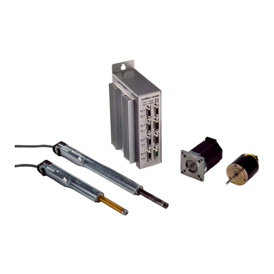
® used in mixed system configurations with the LinMot linear drives. ® Figure 3-1: Mixed system configuration consisting of two linear motors LinMot ® a LinMot E electronic unit as well as a stepper motor and an electromagnet. User Manual V1.01... -
Page 11: Actuator: Linear Drive Linmot
LinMot P linear motors are intrinsically free of mechanical play, gearing or ® belt wear. The enormous dynamic properties and compact construction of LinMot make a variety of applications and novel constructions possible. ® Figure 3-2: Electromagnetic direct linear motor LinMot ®... -
Page 12: Substitution Possibilities Of Linmot P
® 3.3 Substitution possibilities of LinMot ® Depending on the application, LinMot P can substitute the following conventional... -
Page 13: Technical Properties Of Linmot P
LinMot System Overview ® 3.4 Technical properties of LinMot ® The linear drives LinMot P are characterized by the following properties: • Connection to commercially available PLC and PC control systems • Position controlled and curve-driven operation •... -
Page 14: Driving And Operating Modes Of Linmot
® feedback information. The following sections will implicitly refer to LinMot P linear motors as actuators when no specific indication is provided. In this case the target value consists in the position set value to which the drives should move, while the feedback information typically represents a following error message. - Page 15 LinMot System Overview 1. Example: Online specification of an exact reference curve An higher-level control system PC / PLC mode: ‘analog out’ outputs a reference curve online ‘analog’ ‘analog out’ LinMot for the motor to follow exactly.
- Page 16 LinMot System Overview 4. Example: Digital selection between two reference curves Following a trigger signal from a ‘trigger out’ high PLC, the motor moves between two given position following predefined trajectories. PC / PLC mode: ‘two position’...
-
Page 17: Connection To Higher-Level Control Systems
E can be controlled by higher-level control systems directly by means of analog or digital input/output signal lines. The necessary ® parameterisation is done with the LinMot Talk software via an RS-232 connection. Networking via CAN-bus or RS-232 is also possible on specific customer request. -
Page 18: Protection And Error Behavior
3.7.1 Internal protection functions The integrated sensors and complex monitoring programs allow the detection and ® handling of thermal overloading of the LinMot E and P components by means of warning and/or error messages. There is further the possibility to monitor the voltage ®... -
Page 19: Operation And Configuration
LinMot System Overview 3.8 Operation and configuration 3.8.1 System configuration ® The configuration and commissioning of the LinMot systems is done by means of the ® MS-Windows based software LinMot Talk. All the parameters can be displayed clearly, ®... -
Page 20: Curve Generation
LinMot System Overview 3.8.2 Curve generation Predefined reference curves can be executed on trigger signals in different operating modes. The shapes of these curves can be generated automatically by means of the Curve Creator, or can be edited manually point by point as Excel tables. -
Page 21: Monitoring Function (Digital Oscilloscope)
System Overview 3.8.3 Monitoring function (digital Oscilloscope) ® Quick commissioning and optimization of a LinMot system is supported by the built-in monitoring function. With it, the reference curves can be compared with the movements actually executed with no need for additional sensors, etc. The differences between the two curves can give indirect hints on counteracting forces and friction forces which can be useful when adjusting the controller parameters. -
Page 22: Error Logbook
System Overview 3.8.4 Error logbook ® Thanks to the system clock built in the LinMot E electronic units the errors that have occurred during operation can be logged on a time basis. The information is stored in the non volatile memory and allows a later reconstruction of the events. -
Page 23: Customer Specific Applications
System Overview 3.9 Customer specific applications ® The goal in the basic philosophy of LinMot is to be able to cover the broadest range of applications simply by configuring the basic system, without special customer specific adjustments. In some cases (big series, special system environments) however customer specific adjustments can make sense. -
Page 24: Design And Installation
This chapter shows the basic functions of the LinMot system explaining the –AT functionality as an introduction. For extended functionality of –MT and –DP electronic units, please read the manual for SW Rel. 1.3. -
Page 25: Analog Position Setting
In applications where the movement has to be executed with a controlled acceleration, the enormous acceleration capabilities of the linear drives of the LinMot series can be a disturbing factor. For this reason the maximal allowed acceleration and speed for each motor can be specified individually. -
Page 26: Analog Current Setting
LinMot Design and Installation To make sure that the stepper motor will not miss steps on very fast changes of the position set value, a maximal acceleration and a maximal rotational speed can be specified, that will not be exceeded in case of jumps in the reference position signal. -
Page 27: Running Reference Curves
Figure 4-6: Running reference curves LinMot P When using the linear motors of the LinMot P series two reference curves can be saved for each motor. These will be run after each corresponding state change of the trigger signal. The slider then maintains the last position of the curve until the next trigger starts the other curve. -
Page 28: Set Values Through The Serial Interface
LinMot Design and Installation 4.1.5 Set values through the serial interface The following serial hardware interfaces are available: RS232 For standard RS232 serial protocol and commands, please refer to the SW Rel. 1.3 manual RS485 For standard RS485 serial protocol and commands, please refer to the SW Rel. 1.3 manual. -
Page 29: Operating States
LinMot Design and Installation 4.2 Operating states The operating modes described in the previous chapter have shown how the actuators can be driven when the electronic unit is on (i.e. when it is in the state RUN). This chapter gives a description of all the operating states. -
Page 30: Operating State "Setup
LinMot Design and Installation Status display The actual operating mode can be read at all times from the four status LEDs on the front of the electronic unit. READY The system has started correctly FAULT An error has occurred... -
Page 31: Operating State "Run
LinMot Design and Installation Freie FREEZE is a substate of the DRIVE INIT state that can be reached by means of the Freeze control signal. In the substate FREEZE all actuators remain powered and controlled in their respective actual positions. After resetting the Freeze control signal the system returns to the state DRIVE INIT unchanged. -
Page 32: Position Monitoring
LinMot Design and Installation 4.3 Position monitoring The different operating modes for driving the electronic unit from a higher-level control system have been shown in chapter 4.1. In almost all application cases the higher-level control system will need additional information and feedback about the actual positions of the driven actuators. -
Page 33: Position Range Monitoring
LinMot Design and Installation 4.3.2 Position range monitoring In cases where two actuators share a common motion range, the higher-level control must be sure the first actuator is outside the motion range of the second one before moving the latter to it. -
Page 34: Initialization
Three types of initialization are available for the linear motors of the LinMot P series: When initializing, the slider is moved with a user-definable speed until it encounters a Initialization stop. - Page 35 LinMot Design and Installation Figure 4-11: Initialization with a position sensor The trigger signal of the sensor is forwarded to the electronic unit by the higher-level control system. Here, too, it can be specified whether the system should consider the active edge of the trigger signal when the slider is moved inwards or outwards.
-
Page 36: Stepper Motors
LinMot Design and Installation 4.4.2 Stepper motors Stepper motors have to be initialized every time they are turned on. As they can only be operated without a pick-up, their actual position cannot be detected when the rotor is moved in a non-powered mode (e.g. -
Page 37: Signal Interfaces
LinMot Design and Installation 4.5 Signal interfaces The signal interfaces of the electronic unit families E100/E200/E400 and E1000/E2000/E4000 are identical and are described together in this chapter. Sys 1 STOP - STOP+ FREEZE+ LinMot -E400 ... - Page 38 LinMot Design and Installation STOP Starts the “Emergency Stop” behavior that was specified. Here it can specified whether the slider should be stopped with the maximal allowed acceleration, taken to a predefined emergency stop position or the motor should be turned off.
-
Page 39: Sys2 Connector
LinMot Design and Installation Message output can be defined via the configuration software to suit your needs +5V / GND 5V supply (digital). Output with a maximal load capability of 50mA Caution: the pins 4,8,9,10 of Sys1 are exclusively for debugging purposes and must not be connected. -
Page 40: Com Connector
LinMot Design and Installation 4.5.3 COM connector This port serves the connection to the serial interface of a PC for the configuration with the LinMot Talk software. Description Description RS-232 TX RS-232 RX Table 4-3: Pin configuration of the COM connector A 9-pole interface cable with 1:1 connections is needed for the connection of the electronic unit to a PC. -
Page 41: Actuator Interfaces
4.6.1 Connection of LinMot P linear motors The sensor signals and the power signals of the linear motors of the LinMot P series are carried on a single cable. ® By default the LinMot drives come factory-fitted with a cable. -
Page 42: Connecting Stepper Motors
LinMot Design and Installation Only the special LinMot cable (Art. No. 0150-1920) must be used for extension cables. In applications where the motor cable has to be or moved during operation, the special trailing chain cable (Art. No. 0150.1927) must be used (max. 10m). -
Page 43: Connecting The Power Supply
LinMot Design and Installation 4.7 Connecting the power supply The supplies for the signal circuitry and for the power circuitry are carried out separately. For machines where the actuators have to be turned off in case of an emergency stop, the linear motors can be shut down simply by interrupting the supply to the power circuitry. -
Page 44: E1000/E2000/E4000 Supply
Practical applications have shown that in most cases, even when driving four linear motors LinMot P at the same time with one E400 electronic unit a power supply of 48V/300W is sufficient. 4.7.2 E1000/E2000/E4000 supply... - Page 45 Practical applications have shown that in most cases, even when driving four linear motors LinMot P at the same time with one E4000 electronic unit a power supply of 72V/600W is sufficient. User Manual V1.01...
-
Page 46: Hw Configuration Of The Electronic Units
LinMot Design and Installation 4.8 HW configuration of the electronic units The electronic units consist of a signal board and a power board that you can configure to suit your own requirements. To configure the boards you must remove the heat sink and open the case. This is done by removing all the screws. - Page 47 COM interface The Com interface for configuring the electronic unit via the PC software LinMot Talk is normally operated in the RS232 mode. Upon request an RS485 interface is available.
-
Page 48: Mechanical Installation
The special fixing holes allow for easy mounting and removing of the unit. ® ® The electronic units LinMot E400-AT and LinMot E200-AT are fitted with a heatsink and should be mounted in vertical position to allow better cooling. When mounting the units it is important to take into consideration the fact that the housing temperature can reach 60°... -
Page 49: Constructive Notes On The Installation Of The Linear Motors
® Parallelism error In all constructions where the slider of the LinMot P drives is used to move another longitudinally sliding machine part over direct coupling, an over determinate system arises. - Page 50 Figure 4-23: Load mass mounting Handling the sliders The sliders of the LinMot P motors must be handled with great care. Even minor damage to the slider surface can cause a drastical reduction its lifetime. The slider is a high precision machine element consisting of a thin steel tube and Neodym magnets.
-
Page 51: Configuration Software
Complete parameter sets can be saved, loaded and printed. ® ‘Curve Inspector’ The ‘Curve Inspector’ is used to generate and manage reference curves for the LinMot Electronic. Existing curves can be loaded, saved, merged and printed. New curves can be created in a simple way. -
Page 52: Installation Of The Configuration Software
Open the file “LINTALK.INI” with a text editor. ® Remove the semicolons before the serial interface that you plan to use for LinMot Talk. You can also have both interfaces activated. The following example shows a configuration file in which the COM1 interface is activated. -
Page 53: Introduction
Talk, a blank window with a menu bar appears on the screen. As a first step the entitled user must log in the electronic unit. This is done with the “Login...” command under the “File” menu. After selecting the command a dialog box appears, as shown in figure Figure 5-2. -
Page 54: Commander
Figure 5-3: Commander window 5.6 Control Panel ® With the control panel the user can start or stop the software on the LinMot electronic unit. In case of a fatal system error there is also the possibility to reset the unit. When updating the basis software, the new software can be downloaded to the electronic unit with the “Load”... -
Page 55: Parameter Inspector
LinMot Configuration Software 5.7 Parameter Inspector ® The parameters of the LinMot electronic unit can be displayed and edited with the Parameter Inspector: ® • hierarchical display of the LinMot electronic unit’s parameters • Online and Offline modes •... -
Page 56: Editing The Parameters
Configuration Software 5.7.1 Editing the parameters ® The LinMot software supports different parameter types, that the Parameter Inspector displays in different ways. There are four main groups. Directories contain collections of objects, just like in the Windows interface. These are Directories either parameters or other directories. -
Page 57: Saving And Loading Parameter Sets
LinMot Configuration Software 5.7.2 Saving and loading parameter sets The “import” and “Export” buttons allow loading and saving whole parameter sets. When exporting, it can be chosen whether all the parameters stored in the electronic unit Export or only the ones for a single motor should be saved to the PC. -
Page 58: Verifying Parameter Settings
LinMot Configuration Software 5.7.4 Verifying parameter settings The visibility of some parameters can depend on the settings of other parameters. For example, the initialization mode “Trig Turn Left” would only be visible if a stepper motor had been chosen as the “Drive Type”. When the user changes motor type it cannot be guaranteed that the correct initialization mode will be automatically selected. -
Page 59: Write-Protected Parameters
5.7.7 Online mode ® The user normally works in the Online mode. This means that the LinMot electronic unit is connected directly to the PC via a serial interface. Changes in the parameters are ®... -
Page 60: Curve Inspector
LinMot Configuration Software 5.8 Curve Inspector With the Curve Inspector the user disposes of a simple way to generate and modify reference curves for the different drive types. Curves can be loaded from files or from the electronic unit, edited and combined, and finally saved to a file or to the electronic unit. - Page 61 LinMot Configuration Software Memory window This window displays the curves in the same order as they are selected and written to the electronic unit. The information displayed is the same as in the curve window. Status window The current actions and error messages are displayed in this window.
- Page 62 LinMot Configuration Software Scroll buttons Up: All the selected curves are shifted up by one position by clicking on this button. Down: All the selected curves are shifted down by one position by clicking on this button.
-
Page 63: Curve Editor Interface
LinMot Configuration Software 5.8.3 Curve Editor interface Reference curves can be created in different ways with the help of the “Wizards”. The input possibilities and the interface are adapted accordingly. The Curve Editor is used to edit the curves. -
Page 64: Operational Elements Of The Curve Editors
LinMot Configuration Software Curve definitions Curve parameters Graph Edit buttons Close buttons Graph buttons Figure 5-10: Curve Editor for calculated curves The settings are edited in the left panel of the window, while the curve is displayed graphically in the right panel. - Page 65 Drive Type: This specifies for which type of drive the curve is to be generated. The following choices are available: “LinMot Pxx-xx", "Stepper" and "Magnet". Name: The name of the curve is free, as long as it doesn’t exceed 22 characters in length.
-
Page 66: Creating Curves With The Wizards
LinMot Configuration Software Calculate: The curve is calculated according to the selected wizard and the settings made. A dialog box with a suggested number of points is displayed. The user can accept the value or set a specific number of points for the curve. This button is visible for the “Ramp”, “Sine”... -
Page 67: Defining Reference Curves In Excel
LinMot Configuration Software 5.8.6 Defining reference curves in Excel Users with high requirements in the creation of reference curves can create and/or edit curves with the spreadsheet calculation program Excel. When editing curves in Excel it is important that the format of the curve files is maintained. -
Page 68: Oscilloscope
The Oscilloscope is an important resource that helps the user in the commissioning of ® his drive system. The Oscilloscope offers the possibility to record data on the LinMot electronic unit in real time and then transmit it to the PC to be displayed. It offers the following functions: •... -
Page 69: Setting The Recording Variables
LinMot Configuration Software 5.9.1 Setting the recording variables By setting the recording variables the user specifies which variables are to be sampled during the recording process. The variables panel must be activated before setting the variables (see also Figure 5-11). For each of the two channels the user can select the variable from a list. -
Page 70: Determining The Sample Rate
LinMot Configuration Software Trig on Bit The recording is started upon a state change of the selected bit. In Figure 5-15 the trigger is set to start the recording when a following error occurs on drive C. This setting is used mostly in combination with the “Pretrigger”... -
Page 71: Adjusting The Display
5.9.5 Starting and stopping the Oscilloscope ® Start After clicking on the “Start” button, all the values are checked and sent to the LinMot ® electronic unit. At this point the software on the LinMot electronic unit waits until the trigger condition is satisfied and then starts the recording. -
Page 72: Error Inspector
These buttons control the access to the errors stored in the electronic unit. ® Show: The “Show” command reads the last 16 error entries from the LinMot electronic unit and displays them in the error display. Note that not all the errors that lead to the “Error”... - Page 73 Show: Clicking on the "Show" button of "Actual Warnings" causes the actual warnings to be read and displayed. ® The actual errors and warnings can only be displayed when the software on the LinMot electronic unit is started. User Manual V1.01...
-
Page 74: Tutorial A: First Steps
“OK” button. After successful login, the Commander is displayed. ® The Commander gives access to all the modules of the LinMot Talk program. In this example we will use the Parameter Inspector and the Curve Inspector modules. -
Page 75: Tutorial B: Operating The Oscilloscope
We open the Curve Inspector and create a new curve. Here we set “Drive Type” to “LinMot”. Under “Wizard Type” we select “Manual” and we enter 1000 ms for “Time”. Then we enter six values, the first 3 set to 5 mm, the others set to 50 mm. -
Page 76: Oscilloscope Configuration For The Recording Of The Position Set Value
LinMot Configuration Software 5.12.3 Oscilloscope configuration for the recording of the position set value In this example the Oscilloscope will be used to display the actual value and the set value of the position. For this we open the Oscilloscope by clicking on the “Osci” button in the Commander. -
Page 77: Oscilloscope Configuration For The Following Error Monitoring
As a next step we choose the trigger source. We set the “Trigger Mode” to “Trig on bit” and select “Follow Warning”, “Drive A” as “Var”. We select “Up” for the active edge. -
Page 78: Final Remark
Oscilloscope. In order to become even more accustomed with this tool, it is advisable to test different settings (for example recording and defining other curves and motors, or ® combinations with the other LinMot Talk modules: Curve Inspector, Curve Creator and Parameter Inspector). -
Page 79: Tutorial C: Generating Reference Curves
We assume the following: • The LinMot ® electronic unit (Ex00-AT or Ex000-AT) is ON • A linear motor LinMot Pxx-23 or Pxx-37 is connected to the "Mot A" port • The LinMot ® electronic unit is connected to the PC •... -
Page 80: Linear Out" Curve
“Start Point” and “End Point”. We now make sure that “LinMot Pxx-23” is selected as “Drive Type”. If you wish to realize this example with a Pxx-37 choose “LinMot Pxx-37” as “Drive Type”. In the following this alternative will only be shown between parenthesis. - Page 81 LinMot Configuration Software We enter 5 [mm] for the “Start Position” and 50 [mm] for the “End Position”. The curve is now completely defined and we can click the “Calculate” button The following dialog box appears: Figure 5-23: Dialog box for the number of points The number of points can be increased at this stage in case the accuracy of the “Time”...
-
Page 82: Hold" Curve
Configuration Software 5.13.2 "Hold" curve As next step we want to define the middle section of the curve, in which the motor holds the position at 50 mm during half a second. We open a new curve by clicking on the “Create Curve”... -
Page 83: Jump Back" Curve
We open a new curve with “Create Curve” and set the “Wizard Type” to “Point to Point”, “Drive Type” to “LinMot”and name the curve to “Jump Back”. We cannot edit the time. The curve should bring the slider back, therefore we set the “Start Point” to 50 mm and the “End Point”... -
Page 84: Saving Curves
LinMot Configuration Software 5.13.4 Saving curves In order not to loose the curves created, we want to save all three to a file. For this purpose we select them all with the mouse and click on the “Right” button . - Page 85 LinMot Configuration Software Figure 5-28: "Motion" curve We close the Curve Editor with “OK”. User Manual V1.01 5-35...
-
Page 86: Writing Curves To The Electronic Unit
Configuration Software 5.13.6 Writing curves to the electronic unit As a last step we want to write the defined curves to the electronic unit, so that we can see the actual movement be executed by the motor. We select the “Motion” curve in the curve window and move it to the download window by clicking on the “Right”... -
Page 87: Tutorial D: Defining Curves With Excel
LinMot Configuration Software 5.14 Tutorial D: Defining curves with Excel In this chapter we take a look at how to define and edit curves with Excel. It is assumed that you are already accustomed to using the Curve Inspector and the Curve Editor. - Page 88 LinMot Configuration Software We will edit the “Exponential” curve, so that an exponential jump from 5 to 50 mm is executed. For this we define the exponents in column C with the values 0, 0.3, 0.6, ...
- Page 89 LinMot Configuration Software We now load the file in the Curve Inspector (ExelTest.csv) and take a look at the curve, that should appear as follows: Figure 5-32: “Exponential” curve There are many other possibilities in Excel. Some are listed here briefly: •...
-
Page 90: Parameters
LinMot Parameters 6. Parameters Refer to User Manual for SW Rel. 1.3. User Manual V1.01... -
Page 91: Service
LinMot Service 7. Service Refer to User Manual for SW. Rel. 1.3. Benutzerhandbuch V1.01 Sulzer Electronics AG...
Need help?
Do you have a question about the Step and is the answer not in the manual?
Questions and answers