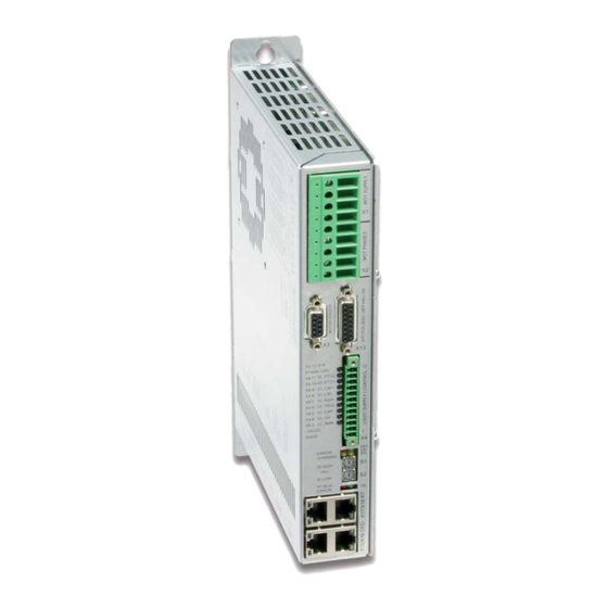
Summary of Contents for LinMot E1250-LU-UC
- Page 1 LinUDP V2 Interface Manual Documentation of the LinUDP V2 Interface of the following Drives: · E1250-LU-UC · C1250-LU-XC · E1450-LU-QN V2 November 2019 Doc.: 0185-1108-E_1V9_MA_LinUDP_V2...
- Page 2 NTI AG. LinMot® is a registered trademark of NTI AG. Note The information in this documentation reflects the stage of development at the time of press and is therefore without obligation.
-
Page 3: Table Of Contents
5 LinUDP V2 Parameters ..........................9 6 LinUDP V2 Modules ..........................10 6.1 Master to drive Modules ........................10 6.2 Drive to master Modules ........................10 7 Real Time Config Module ........................12 NTI AG / LinMot Page 3 of 20... -
Page 4: Overview
(C1250-LU-XC) in the name. On this drives the old LinUDP version does not run. 2 Installation on Servo Drive For installing the LinUDP V2 firmware on the servo drive, start the LinMot- Talk software and press the install firmware button . - Page 5 The use of these switches depends on the type of fieldbus which is used. Please see the corresponding manual for further information. Important: The switch value S1 = S2 = 0 (factory default setting) is a special configuration which acquires the IP address via DHCP. NTI AG / LinMot Page 5 of 20...
-
Page 6: Linudp V2 Telegram
The first 32 bits of the LinUDP V2 data define the request and the following 32 bits define the format of the response. The following tables show how the request definition and the response definition look like. Each of this parts have a byte order with Low Byte First. Page 6 of 20 NTI AG / LinMot... - Page 7 Each field represents one byte. 0. Byte 1. Byte 2. Byte 3. Byte 4. Byte 5. Byte 6. Byte 7. Byte Request Definition Response Definition Control Word MC Interface Realtime Configuration NTI AG / LinMot Page 7 of 20...
-
Page 8: Response From The Drive
2. Byte 3. Byte 4. Byte 5. Byte 6. Byte 7. Byte Request Definition Response Definition Status Word State Var Actual Position Demand Position Current Warn Word Error Code Monitoring Channel Realtime Configuration Page 8 of 20 NTI AG / LinMot... -
Page 9: Linudp V2 Parameters
5 LinUDP V2 Parameters The LinUDP servo drives have an additional parameter tree branch, which can be configured with the distributed LinMot-Talk software. With these parameters, the LinUDP V2 behaviour can be defined. The LinMot-Talk software can be downloaded from http://www.linmot.com... -
Page 10: Linudp V2 Modules
Demand Position Returns the demand position of the motor. (32 Bit integer value, resolution 0.1 µ m) Current Returns the set current of the motor. (16 Bit integer value, resolution 1 mA) Page 10 of 20 NTI AG / LinMot... - Page 11 Returns the error code. Please refer to “User Manual Motion Control Software” for the Error Codes of the MC software. Monitoring Channel Transmits cyclically the value of the variable, which is defined by the monitoring channel Parameter (LinUDP- V2-Parameters NTI AG / LinMot Page 11 of 20...
-
Page 12: Real Time Config Module
Read ROM Value of Parameter by UPID Read RAM Value of Parameter by UPID Write ROM Value of Parameter by UPID Write RAM Value of Parameter by UPID Write RAM and ROM Value of Parameter by UPID Page 12 of 20 NTI AG / LinMot... - Page 13 Get Error Log Entry Time high Get Error Code Text Stringlet Command Table Command Table: Save to Flash Command Table: Delete All Entries (RAM) Command Table: Delete Entry Command Table: Write Entry Command Table: Write Entry Data NTI AG / LinMot Page 13 of 20...
- Page 14 Curve already defined / Curve not present (Curve Service) Overview Parameter access Word Parameter Channel Control Parameter Channel Status Parameter UPID Parameter UPID Parameter Value Low Parameter Value Low Parameter Value High Parameter Value High Overview Curve access: Page 14 of 20 NTI AG / LinMot...
- Page 15 Curve Number Curve Number Data Value Low / Info Block size Data Value Low / Info Block size Data Value High / Data Block size Data Value High / Info Block size NTI AG / LinMot Page 15 of 20...
- Page 16 Parameter Channel Status Start UPID (search from this UPID) Get next Modified UPID List item (Command ID 23h): Word Parameter Channel Control Parameter Channel Status UPID found Data Value Low Data Value High Page 16 of 20 NTI AG / LinMot...
- Page 17 Error Code Error code Stringlet Number (0..7) Stringlet Byte 0 and 1 Stringlet Byte 2 and 3 Command Table: Save to Flash (Command ID 75h): Word Parameter Channel Control Parameter Channel Status NTI AG / LinMot Page 17 of 20...
- Page 18 Parameter Channel Control Parameter Channel Status Entry Number Entry Number Data Data Data Data Command Table: Get Entry (Command ID 85h): Word Parameter Channel Control Parameter Channel Status Entry Number Entry Number Block Size Page 18 of 20 NTI AG / LinMot...
- Page 19 Word Parameter Channel Control Parameter Channel Status Offset in bytes Bit field (Bit set = undefined / Bit cleared = used) Bit field (Bit set = undefined / Bit cleared = used) NTI AG / LinMot Page 19 of 20...
- Page 20 LinMot USA Inc. N1922 State Road 120, Unit 1 Lake Geneva, WI 53147 Phone: 262-743-2555 E-Mail: usasales@linmot.com Web: http://www.linmot-usa.com/ Please visit http://www.linmot.com/contact to find the distribution close to you. Smart solutions are... Page 20 of 20 NTI AG / LinMot...


Need help?
Do you have a question about the E1250-LU-UC and is the answer not in the manual?
Questions and answers