
Related Manuals for LinMot C1251-MI-XC-2S-XE


Summary of Contents for LinMot C1251-MI-XC-2S-XE
- Page 1 PROFINET PROFIdrive Interface Manual Documentation of the PROFIdrive Interface of the following Drives: · C1251-MI-XC-2S-XE · C1250-MI-XC-PD-1S February 2022 Doc.: 0185-1154-E_1V1_MA_PROFIdriveMI...
- Page 2 NTI AG. LinMot® is a registered trademark of NTI AG. Note The information in this documentation reflects the stage of development at the time of press and is therefore without obligation.
-
Page 3: Table Of Contents
2.1.6 Siemens telegram 105, PZD-10/10 ..................12 2.1.7 Siemens telegram TDB 200, PZD-3/1 ................... 13 2.1.8 Real Time Config telegram 404, PZD-4/4 ................14 2.1.9 LinMot telegram 516 PZD-16/13 ................... 14 2.1.10 Supplement telegram 701, PZD-2/5 ..................15 2.1.10.1 Output Data ........................ 15 2.1.10.2 Input Data ........................ - Page 4 6.2.7.1 Assign LinMot drive to the PLC ..................30 6.2.7.1.1 Define the PROFINET Topology ................32 6.2.8 Configure communication module to the LinMot PROFIdrive ........... 32 6.2.8.1 Add Safety Telegram 30 ....................33 6.2.8.2 Safety Parameters in LinMot Talk ................... 34 6.3 Creating Technology Objects ....................
-
Page 5: System Overview
1 System overview PROFINET is an open real-time Ethernet network. In this manual the PROFIdrive profiles of LinMot drives are described. The LinMot drive acts as a slave in this network and is implemented with the netX chip from Hilscher. - Page 6 Page 6 of 44 NTI AG / LinMot...
-
Page 7: Process Data Object (Pdo) Configuration
STW1 Uint16 2, 3 NSOLL_B Int32 STW2 Uint16 G1_STW Uint16 Input Data Index Size Byte Name Data [Byte] Offset Type Tlg 3 Variables RECORD ZSW1 Uint16 2, 3 NIST_B Int32 ZSW2 Uint16 NTI AG / LinMot Page 7 of 44... -
Page 8: Standard Telegram 5, Pzd-9/9
The standard telegram 7 is defined for positioning mode. Content: Positioning interface (Program submode) Output Data Index Size Byte Name Data [Byte] Offset Type Tlg 7 Variables RECORD STW1 Uint16 SATZANW Uint16 Page 8 of 44 NTI AG / LinMot... -
Page 9: Standard Telegram 9, Pzd-10/5
Jog 1 signal source Jog Move - Jog 2 signal source Control via PLC Control by PLC (1) / No Control by PLC (0) Home Start Homing (1) / No Homing (0) Details of SATZANW NTI AG / LinMot Page 9 of 44... -
Page 10: Input Data
Switch On Inhibited (1) / Switch On Not Inhibited (0) Warning Present Warning Present (1) / No Warning Present (0) Within Tolerance Range Following Error within tolerance range (1) / Following Error out of tolerance range (0) Page 10 of 44 NTI AG / LinMot... -
Page 11: Safety Standard Telegram 30
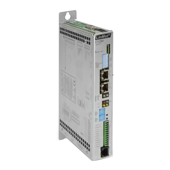
XIST_A is position actual value. 2.1.5 Safety Standard telegram 30 This telegram is applicable only for the 2S drive - C1251-MI-XC-2S-XE. Control of the Drive Safety Process inside the DO by the Safety Application Controller. The details of the safety telegram is described in Safety Manual for 2S drive. -
Page 12: Input Data
2.1.6 Siemens telegram 105, PZD-10/10 Siemens telegram 105 can only support IRT mode. Output Data Index Size Byte Name Data [Byte] Offset Type Tlg 105 Variables RECORD STW1 Uint16 2, 3 NSOLL_B Int32 STW2 Uint16 Page 12 of 44 NTI AG / LinMot... -
Page 13: Siemens Telegram Tdb 200, Pzd-3/1
Value at UPID 0x13FC/0x13FE = (B+) pos torque Limit * maximal Motor Current / 4000h Value at UPID 0x13FD0/x13FF = -(B-) neg torque Limit * maximal Motor Current / 4000h Input Data NTI AG / LinMot Page 13 of 44... -
Page 14: Real Time Config Telegram 404, Pzd-4/4
Config Status Word Uint16 Config Index/.. Uint16 4, 5 Config Value Word32 Please refer to the document 0185-1074-E_1V7_MA_Drive-Configuration-Over-Fieldbus-SG5-SG7.pdf [3] from LinMot for more details. 2.1.9 LinMot telegram 516 PZD-16/13 Default-IO mapping with Config Output Data Index Size Byte Name Data [Byte]... -
Page 15: Supplement Telegram 701, Pzd-2/5
For the meaning of the variables 1-6 refer to [2], for the „Real Time Config Interface“ refer to [3]. 2.1.10 Supplement telegram 701, PZD-2/5 This telegram is applicable only for the 2S drive - C1251-MI-XC-2S-XE. The predefined PROFIdrive supplementary safety telegrams 700 and 701 of Siemens are available for the transfer of the "... -
Page 16: Input Data
Details of S_ZSW3B Name Significance Brake test Brake test selected (1) / Brake test deselected (0) Reserved Active brake Not used, default 0 Brake test active Test active (1) / Test not active (0) Page 16 of 44 NTI AG / LinMot... -
Page 17: Siemens Telegram 750, Pzd-3/1
S_V_LIMIT_B = UPID 1A2Ah / UPID 2061h * 0x40000000 2.1.11 Siemens telegram 750, PZD-3/1 Telegram 750 is the same as telegram 200. Telegram 750 is used with S7-1500 PLC. This telegram is used for the 2S drive - C1251-MI-XC-2S-XE. Output Data Index... -
Page 18: Output Pdo Modules
Tlg 405 Variables RECORD 1, 2 Actual Position Int32 2.3.2 Demand Position telegram 406, PZD 0/2 Index Size Byte Name Data [Byte] Offset Type Tlg 406 Variables RECORD 1, 2 Demand Position Int32 Page 18 of 44 NTI AG / LinMot... -
Page 19: Warnword Telegram 407, Pzd 0/1
1, 2 Mon Channel 2 Word32 2.3.8 Mon Channel 3 telegram 412, PZD 0/2 Index Size Byte Name Data [Byte] Offset Type Tlg 412 Variables RECORD 1, 2 Mon Channel 3 Word32 NTI AG / LinMot Page 19 of 44... -
Page 20: Mon Channel 4 Telegram 413, Pzd 0/2
Actual Velocity Int32 2.3.13 Supplement telegram 700, PZD-0/3 Index Size Byte Name Data [Byte] Offset Type Tlg 700 Variables RECORD S_ZSW1B Uint16 S_V_LIMIT_B Int32 Please refer to telegram 701 for the details. Page 20 of 44 NTI AG / LinMot... -
Page 21: Asynchronous Configuration Protocol
Number list of defined parameter 60000 Velocity reference value(not yet implemented) LinMot PROFIdrive Object Dictionary. 3.2 Manufacturer specific Profile Area The RAM and ROM values of the drive parameters can be accessed by their parameter number (UPID) added with an offset of 0x2000 (UPID+0x2000). - Page 22 Request ID Description 0x42 Write ROM value of parameter, only valid with the value attribute Page 22 of 44 NTI AG / LinMot...
-
Page 23: Profidrive Parameters
& manuals. 4.1.1 PROFdrive/Dis-/Enable With the Dis-/Enable parameter the LinMot Servo Drive can be run without the Ethernet PROFIdrive Interface going online. So in a first step the system can be configured and run without any bus connection. PROFIdrive/Dis-/Enable Disable Servo Drive runs without PROFINET. -
Page 24: Profidrive/Parameter Channels
MC-SW motion command. With the default value of 1’000 the transmitted acceleration values have a resolution of [0.01m/s^3]. With a value of 100’000 they will have a resolution of [1m/s^3]. Page 24 of 44 NTI AG / LinMot... -
Page 25: Profidrive/Axis Configuration/G1 Configuration
Wire color code Assignment 100 BASE-TX WHT/ORG WHT/GRN WHT/BLU WHT/BRN case RJ-45 Use standard patch cables (twisted pair, S/UTP, AWG26) for wiring. This type of cable is usually referred to as a “Cat5e-Cable”. NTI AG / LinMot Page 25 of 44... -
Page 26: Example Setup
6.1 Setup in S7-1500 System In the following steps the integration of the LinMot Safety PROFIdrive with the LinMot linear motor into the S7- 1500 is described. In this example, the PLC used is Siemens S7-1500 with CPU 1517F-3 PN/DP. The TIA portal V16.0 software with Step 7 safety is used for the development. -
Page 27: Configure A Device
Create new project 6.2.2 Configure a Device Configure the device 6.2.3 Add new Device Select the PLC device NTI AG / LinMot Page 27 of 44... -
Page 28: Select Plc Controller
Add the PROFINET network PN/IE_1 here and choose the IP-address and subnet netmask. Configure the Profinet, set the PLC netw ork address Define the S7-1500 as Sync master in the real time settings. Configuring the PLC as Sync-m aster Page 28 of 44 NTI AG / LinMot... -
Page 29: Install Linmot Gsdml Device Description File
LinMot\LinMot-Talk 6.10 - Build 2021xxxx\Firmware\Interfaces\ProfiNet\GSDML_PD If not installed altready, install the LinMot GSDML file Choose the source path and select the GSDML file. Please note that the article number of the drive "31005" is in the xml file name. -
Page 30: Configure Linmot Profidrive To Profinet Network
6.2.7 Configure LinMot PROFIdrive to PROFINET network Now change to the network view and add the desired LinMot PROFIdrive device from the hardware catalogue. Select the LinMot drive and drag and drop it to the PN/IE1 network. Connect to the PN/IE netw ork 6.2.7.1 Assign LinMot drive to the PLC... - Page 31 Edit the IP address by choosing " Properties > Profinet interface [X1] > Ethernet addresses" under IP protocol enter the required IP address and choose the Subnet mask. Assign the IP address NTI AG / LinMot Page 31 of 44...
-
Page 32: Define The Profinet Topology
Assign the drive to PLC in topology view 6.2.8 Configure communication module to the LinMot PROFIdrive Double click in the Topology view the LinMot drive, then automatically the device view of the LinMot drive opens. In the section Module, select DO SERVO. Double click on the item. -
Page 33: Add Safety Telegram 30
"Isochronous mode" check box. 6.2.8.1 Add Safety Telegram 30 The LinMot drive C1251 supports the following safety functions - STO, SOS, SS1, SS2, SLS0, SLS1, SLS2, SLS3. For details of the functionality, refer to the User Safety Manual. The functional block for safety functions are added to PLC_1. This block is compatible (or reusable) with the functional block used for Siemens safety drive S120. -
Page 34: Safety Parameters In Linmot Talk
6.2.8.2 Safety Parameters in LinMot Talk The safety parameters are programmed in the LinMot talk. They are given in yellow color under Parameters. For the proper operation of the safe bus it is required to assign the parameter "Safety > General Settings >... -
Page 35: Configure Axis
Click on OK. Select the postiioning axis 6.3.1 Configure axis Open the "Configuration" window. Choose axis type as linear if linear motor is used. The basic parameters could be left as suggested. NTI AG / LinMot Page 35 of 44... - Page 36 Basic param eter in TO Page 36 of 44 NTI AG / LinMot...
- Page 37 After assigning the process image of the drive, all the below fields will be automatically filled. Drive configuration in TO In the Data exchange with drive session, choose the reference speed as 12000.0 1/min and maximum speed as 24000.0 1/min. Data exchange w ith the drive configuration NTI AG / LinMot Page 37 of 44...
-
Page 38: Compile And Download Plc_1 Configuration
In the Data exchange with encoder session, choose the measuring system as linear. The resolution should be 100nm under "Distance between increments" because the LinMot drive works with a fix resolution of 100nm. Set the "Bits in Gx_XIST1" in fine resolution to 0. -
Page 39: Move The Axis With The Commissioning Panel
In the next step you have to acknowledge the safety internal event before enabling the drive. In this example the signal "Safety_Error_Ack" is assigned to the safety control word 0 bit 7. NTI AG / LinMot Page 39 of 44... - Page 40 Axis control panel for com m issioning We have to get the master control by clicking on activate. After clicking the system will go online automatically. Click on "yes" and accept the activation. Page 40 of 44 NTI AG / LinMot...
- Page 41 In the next step you have to set the enables, click the "Enable" button. Axis control panel for com m issioning The LinMot talk shows the "Operation Enabled" state in the monitoring panel. Set the home position by choosing the "Set home position" command from the drop down list under "Operating mode".
- Page 42 Otherwise reduce this value. Then click Start. Axis control panel for com m issioning Check the position in the current value of position in the axis control panel. Axis control panel for com m issioning Page 42 of 44 NTI AG / LinMot...
- Page 43 Axis control panel for com m issioning Before leaving the control panel click the "Axis > Disable button" . Then click on "Master control > Deactivate". Now the LinMot-Talk is in "Ready to Switch On" state. LinMot talk status after deactivation...
- Page 44 LinMot USA Inc. N1922 State Road 120, Unit 1 Lake Geneva, WI 53147 Phone: 262-743-2555 E-Mail: usasales@linmot.com Web: http://www.linmot-usa.com/ Please visit http://www.linmot.com/contact to find the distribution close to you. Smart solutions are... Page 44 of 44 NTI AG / LinMot...
Need help?
Do you have a question about the C1251-MI-XC-2S-XE and is the answer not in the manual?
Questions and answers