LinMot E1100-CO Drive Data Sheet & Installation Manual
Documentation for installing the following drives, rs485, profi bus, rs232, easy steps, canopen, devicenet
Hide thumbs
Also See for E1100-CO:
- Data sheet & installation manual (24 pages) ,
- Installation manual (20 pages) ,
- User manual (11 pages)
Table of Contents
Advertisement
Documentation for installing the following Drives:
Für eine Deutsche Version bitte den Support kontaktieren
Please visit http://www.linmot.com to check for the latest version of this document!
E1100-CO (-HC, -XC)
-
-
E1100-DN (-HC, -XC)
-
E1100-RS (-HC, -XC)
-
E1130-DP (-HC, -XC)
E1100-GP (-HC, -XC)
-
Drive Data Sheet
& Installation Guide
0185-1064-E_3V25_IG_E1100 / August 2018
!
Advertisement
Table of Contents

Subscribe to Our Youtube Channel
Related Manuals for LinMot E1100-CO


Summary of Contents for LinMot E1100-CO
- Page 1 E1100-DN (-HC, -XC) E1100-RS (-HC, -XC) E1130-DP (-HC, -XC) E1100-GP (-HC, -XC) Drive Data Sheet & Installation Guide Für eine Deutsche Version bitte den Support kontaktieren Please visit http://www.linmot.com to check for the latest version of this document! 0185-1064-E_3V25_IG_E1100 / August 2018...
- Page 2 Under the copyright laws, this publication may not be reproduced or transmitted in any form, electronic or mechanical, including photocopying, recording, microfilm, storing in an information retrieval system, not even for didactical use, or translating, in whole or in part, without the prior written consent of NTI AG. LinMot ® is a registered trademark of NTI AG.
-
Page 3: Table Of Contents
E1130-DP (-LC/HC/XC)......................8 FUNCTIONALITY........................9 E1130-DP(-HC, -XC) FUNCTIONS AND WIRING..............10 E1100-GP (-HC, -XC) FUNCTIONS AND WIRING.............11 E1100-CO (-HC, -XC), -DN (-HC, -XC), -RS (-HC, -XC) FUNCTIONS AND WIRING. .12 POWER SUPPLY AND GROUNDING..................13 DESCRIPTION OF THE CONNECTORS / INTERFACES..........14 LED BLINK CODES........................21 PHYSICAL DIMENSION......................22... -
Page 4: Important Safety Notes For E1100 Drives
All connectors must not be connected or disconnected while DC voltage is present. Do not disconnect system components until all LinMot drive LEDs have turned off. (Capacitors in the power supply may not fully discharge for several minutes after input voltage has been disconnected). -
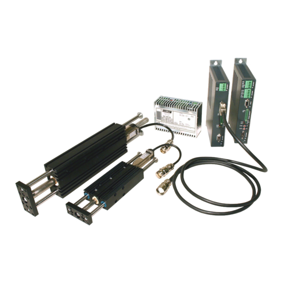
Page 5: System Overview
Installation Guide E1100 System Overview Typical Servo System E1100-XX: Drive, Linear Motor and Power Supply. NTI AG, LinMot Installation Guide E1100 23/08/2018 Page 5/27... -
Page 6: E1100 Interfaces
Installation Guide E1100 E1100 Interfaces E1100-GP (-LC/HC/XC) Page 6 of 27 Installation Guide E1100 23/08/2018 NTI AG/ LinMot/... -
Page 7: E1100-Co/Dn/Rs (-Lc/Hc/Xc)
Installation Guide E1100 E1100-CO/DN/RS (-LC/HC/XC) PowerStageEnable NTI AG, LinMot Installation Guide E1100 23/08/2018 Page 7/27... -
Page 8: E1130-Dp (-Lc/Hc/Xc)
Installation Guide E1100 E1130-DP (-LC/HC/XC) PowerStageEnable Page 8 of 27 Installation Guide E1100 23/08/2018 NTI AG/ LinMot/... -
Page 9: Functionality
● ● ● ● ● ● ● ● ● ● ● ● CAN Multi Axes Configuration ● ● ● ● ● ● ● ● ● ● ● ● ● ● ● NTI AG, LinMot Installation Guide E1100 23/08/2018 Page 9/27... -
Page 10: E1130-Dp(-Hc, -Xc) Functions And Wiring
Installation Guide E1100 E1130-DP(-HC, -XC) Functions and Wiring Page 10 of 27 Installation Guide E1100 23/08/2018 NTI AG/ LinMot/ PowerStageEnable... -
Page 11: E1100-Gp (-Hc, -Xc) Functions And Wiring
Installation Guide E1100 E1100-GP (-HC, -XC) Functions and Wiring NTI AG, LinMot Installation Guide E1100 23/08/2018 Page 11/27... -
Page 12: E1100-Co (-Hc, -Xc), -Dn (-Hc, -Xc), -Rs (-Hc, -Xc) Functions And Wiring
Installation Guide E1100 E1100-CO (-HC, -XC), -DN (-HC, -XC), -RS (-HC, -XC) Functions and Wiring Page 12 of 27 Installation Guide E1100 23/08/2018 NTI AG/ LinMot/... -
Page 13: Power Supply And Grounding
In order to assure a safe and error free operation, and to avoid severe damage to system components, all system components* must be well grounded to either a single earth or utility ground. This includes both LinMot and all other control system components to the same ground bus. -
Page 14: Description Of The Connectors / Interfaces
- Screw thread: M 2,5 - Use 60/75C copper conductors only - Conductor cross-section: use only 2.5mm (AWG 14) - Max. length: 4m Motor Phases LinMot Motor: 3-phase EC-Motor: PH1+ /U Motor Phase 1+ Motor Phase U PH1- /V Motor Phase 1-... - Page 15 If motor phase current exceeds 5A or 7.5A , motor phases must be wired to X2. peak For UL applications the motor phases have to be wired on X2 and not on X3! NTI AG, LinMot Installation Guide E1100 23/08/2018 Page 15/27...
- Page 16 Motor phases may only be connected to X3 if RMS current is below 5A and peak current is below 7.5A. For UL applications the motor phases have to be wired on X2 and not on X3! X4: 12pin Control/Supply (E1130-DP(-HC,-XC), E1100-CO(-HC,-XC), E1100-DN(-HC,-XC), E1100-RS(-HC,-XC)) Input Power Stage Enable (HW Enable) X4.11...
- Page 17 (S3.4). Otherwise the baud rate will be set to 500kBaud. The CAN-Talk ID is always taken from both switches S1 and S2. NTI AG, LinMot Installation Guide E1100 23/08/2018 Page 17/27...
- Page 18 DSUB-9 (m) RS232: Configuration on all drives: use 1:1 connection cable to PC with only pins 2, 3 and 5 connected. Use LinMot RS configuration cable (Art.-No. 0150-3307). Cable length < 30m Page 18 of 27 Installation Guide E1100 23/08/2018...
- Page 19 X7 is internally connected to X8 (1:1 connection) Profibus DP (only available on E1130-DP (-HC, -XC)) Not connected Not connected RxD/TxD-P CNTR-P (isolated) (isolated) Not connected RxD/TxD-N Not connected case Shield NTI AG, LinMot Installation Guide E1100 23/08/2018 Page 19/27...
- Page 20 2MHz (Incremental RS422), 240ns edge separation 10kHz (Analog 1Vpp), 10Bit AD converted Sensor Supply (max. 100mA) Encoder Inputs: - Incremental: RS422 - Sin/Cos: 1Vpp Enc. Alarm In: 5V / 1mA Page 20 of 27 Installation Guide E1100 23/08/2018 NTI AG/ LinMot/...
-
Page 21: Led Blink Codes
Usermanual_LinMot-Talk under chapter trouble shooting. The meaning of the Error Codes can be found in the Usermanual_MotionCtrl_Software_E1100 and the user manual of the loaded interface software. These documents are provided together with LinMot-Talk www.linmot.com configuration software and can be downloaded from... -
Page 22: Physical Dimension
40…50 with power derating Relative humidity 95% (non-condensing) Max. Case Temperature °C Max. Power Dissipation Distance between Drives mm (in) 20 (0.8) left/right 50 (2) top/bottom ( ) dimensions in inch Page 22 of 27 Installation Guide E1100 23/08/2018 NTI AG/ LinMot/... -
Page 23: Power Supply Requirement
88 VDC. For UL applications, use option A. Item Description Art. No. Capacitor 10’000 F / 100 V Capacitor 0150-3075 Regeneration Resistor RR01-10/60 (10 Ohm, 60 W) 0150-3088 NTI AG, LinMot Installation Guide E1100 23/08/2018 Page 23/27... -
Page 24: Ordering Information
Profibus Servo Drive, 72VDC/25A 0150-1861 E1100-RS RS232/485 Drive, 72VDC/8A 0150-1677 E1100-RS-HC RS232/485 Drive, 72VDC/15A 0150-1678 E1100-RS-XC RS232/485 Drive, 72VDC/25A 0150-1862 E1100-CO CANopen Drive, 72VDC/8A 0150-1681 E1100-CO-HC CANopen Drive, 72VDC/15A 0150-1682 E1100-CO-XC CANopen Drive, 72VDC/25A 0150-1683 E1100-DN DeviceNet Drive, 72VDC/8A 0150-1679... -
Page 25: Safety Notes For The Installation According To Ul
Regeneration Resistor: For UL applications pins RR+ and RR- of terminal X1 must not be connected! In case of over voltage see chapter “Regeneration of Power / Regeneration Resistor” Option A. NTI AG, LinMot Installation Guide E1100 23/08/2018 Page 25/27... -
Page 26: Declaration Of Conformity Ce-Marking
Installation Guide E1100 Declaration of Conformity CE-Marking NTI AG / LinMot ® Bodenaeckerstrasse 2 8957 Spreitenbach Switzerland Tel.: +41 (0)56 419 91 91 Fax: +41 (0)56 419 91 92 declares under sole responsibility the compliance of the products: - Drives of the Series E11x0-xx-xx with the EMC Directive 2014/30/EU. -
Page 27: Contact Addresses
Tech. Support: +41-(0)56-544 71 00 support@linmot.com skype:support.linmot Tech. Support (Skype) : Fax: +41-(0)56-419 91 92 www.linmot.com Web: ----------------------------------------------------------------------------------------------------------------------------- LinMot USA Inc. N1922 State Road 120, Unit 1 Lake Geneva, WI 53147 Phone: 262-743-2555 E-Mail: usasales@linmot.com Web: http://www.linmotusa.com/ ----------------------------------------------------------------------------------------------------------------------------- http://www.linmot.com/ Please visit to find the distribution near you.
Need help?
Do you have a question about the E1100-CO and is the answer not in the manual?
Questions and answers