
Related Manuals for Datalogic PowerScan 9501-AR Series


Summary of Contents for Datalogic PowerScan 9501-AR Series
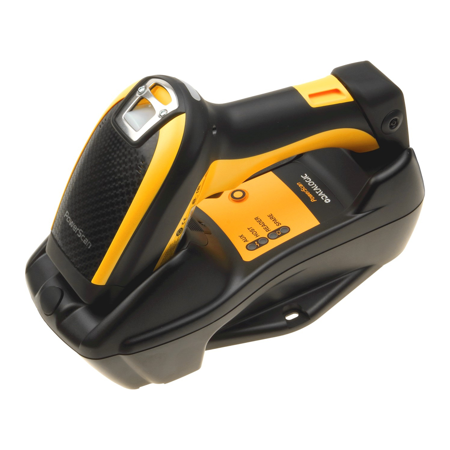
- Page 1 PowerScan™ 9501-AR Family Industrial Corded and Cordless Handheld Auto Range Area Imager Bar Code Reader PowerScan PD9531-AR/PBT9501-AR/PM9501-AR Product Reference Guide...
- Page 2 U.S.A. and the E.U. The Bluetooth word mark and logos are owned by Bluetooth SIG, Inc. and any use of such marks by Datalogic Group companies is under license. PowerScan is a trademark of Datalogic S.p.A. and/or its affiliates, registered in many coun- tries, including the U.S.A and the E.U.
-
Page 3: Table Of Contents
Set Date and Time ......................................19 Linking the Reader ......................................... 20 Link Datalogic RF Devices to Base ................................20 Linking to a Bluetooth Adapter in Serial Port Profile (Slave) Mode ......................20 Linking to a Bluetooth Adapter in Serial Port Profile (Master) Mode ...................... 20 Linking to a Bluetooth Adapter in HID mode ............................. - Page 4 Contents Beep On Not on File ..................................33 ACK NAK Options ..................................34 ACK Character ....................................35 NAK Character ..................................... 35 ACK NAK Timeout Value ................................36 ACK NAK Retry Count .................................. 37 ACK NAK Error Handling ................................38 Indicate Transmission Failure ..............................38 Disable Character ..................................
- Page 5 Contents UPC-E Enable/Disable ................................89 UPC-E Check Character Transmission ............................90 UPC-E 2D Component ................................. 90 Expand UPC-E to EAN-13 ................................91 Expand UPC-E to UPC-A ................................91 UPC-E Number System Character Transmission ........................92 GTIN FORMATTING ....................................92 EAN 13 (JAN 13) ....................................93 EAN 13 Enable/Disable ................................
- Page 6 Contents ISBT 128 Dynamic Concatenation Timeout ..........................124 ISBT 128 Advanced Concatenation Options ........................... 124 INTERLEAVED 2 OF 5 (I 2 OF 5) ................................. 125 I 2 of 5 Enable/Disable ................................125 I 2 of 5 Check Character Calculation ............................126 I 2 of 5 Check Character Transmission ............................
- Page 7 Contents GS1 DataBar™ Limited 2D Component ............................ 160 CODE 93 ....................................... 160 Code 93 Enable/Disable ................................160 Code 93 Check Character Calculation ............................161 Code 93 Check Character Transmission ..........................161 Code 93 Length Control ................................162 Code 93 Set Length 1 ................................163 Code 93 Set Length 2 ................................
- Page 8 Contents MICRO QR CODE ....................................200 Micro QR Code Enable/Disable ..............................200 Micro QR Code Length Control ..............................200 Micro QR Code Set Length 1 ..............................201 Micro QR Code Set Length 2 ..............................202 UCC COMPOSITE ....................................203 UCC Composite Enable / Disable ............................. 203 UCC Optional Composite Timer ..............................
- Page 9 Contents Base Address Stamping ................................245 Base Address Delimiter Character ............................245 RS-485 Master Header/Terminator (Prefix/Suffix) ......................246 RS-485 Cradle Address ................................247 RS-485 Slave Minimum Address ............................. 247 RS-485 Slave Maximum Address ............................248 RS-485 Network Working Mode .............................. 248 RS-485 Network Warning Message ............................
- Page 10 Contents Global Prefix/Suffix .....................................292 Global AIM ID ........................................293 Label ID .........................................294 Character Conversion ....................................299 Reading Parameters ......................................300 Good Read LED Duration ....................................300 Scanning Features .......................................301 Scan Mode ........................................301 Flash On Time ......................................302 Flash Off Time ......................................303 Wireless Features ........................................304 Automatic Configuration Update ................................304 RF Address Stamping ....................................304 PM9501-AR-Only Features ..................................306 Changing System Speed in Normal Mode ..........................
-
Page 11: Introduction
Chapter 1 Introduction About this Manual This Product Reference Guide (PRG) is provided for users seeking advanced technical information, including connection, programming, maintenance and specifications. The Quick Reference Guide (QRG) and other publications associated with this product are downloadable free of charge from the web- site listed on the back cover of this manual. -
Page 12: Manual Conventions
Telephone Technical Support If you do not have internet or email access, you may contact Datalogic tech- nical support at (541) 349-8283 or check the back cover of your manual for more contact information. -
Page 13: About The Reader
Typically, units are factory-programmed for the most common terminal and communications settings. If you need to modify any programmable settings, custom configuration can be done by scanning the programming barcodes within this guide or with Datalogic Aladdin™, available from the Datalogic website. See "Datalogic Aladdin™"... -
Page 14: The Bc9Xx0™ Base Station/Charger
Introduction The BC9xx0™ Base Station/Charger The BC9xx0 base station, when paired with one or more PowerScan™ 9501-AR readers, builds a Cordless Reading System for the collection, decoding and transmission of bar code data. It can be connected to a Host PC via RS-232, USB, or KBD Wedge, and is suited for single-cradle layouts. -
Page 15: Battery Safety
Always charge the battery at 32° – 104°F (0° - 40°C) temperature range. Use only the authorized power supplies, battery pack, chargers, and docks supplied by your Datalogic reseller. The use of any other power supplies can damage the device and CAUTION void your warranty. -
Page 16: Programming The Reader
In addition, Aladdin makes it easy to upgrade the handheld’s firmware, to attain the benefits of new reader features. Reference the Datalogic Aladdin™ Online Help for more details. Aladdin is available for download free of charge on the Datalogic website. PowerScan™ PD9531-AR/PBT9501-AR/PM9501-AR... -
Page 17: Setup
Chapter 2 Setup Unpacking Check carefully to ensure the reader and any accessories ordered are pres- ent and undamaged. If any damage occurred during shipment, contact Dat- alogic Technical Support. Information is shown on page KEEP THE PACKAGING. Should the unit ever require service, it should be returned in its original shipping container. -
Page 18: Connecting The Cable (Corded Versions)
Setup Connecting the Cable (Corded versions) A. Rubber gasket B. Cable Holder C. Cover D. Connector Holder 1. Slip the cable through the Cover. 2. Push the Rubber Gasket onto the Cable Holder. FRONT>> 3. Push the Cable Holder and gasket into the handle. -
Page 19: Configuring The Base Station
Configuring the Base Station Configuring the Base Station To set up your BC9xx0 cradle you must: 1. Physically install the cradle. 2. Make all system connections. 3. Configure the BC9xx0 cradle. Mounting the BC9xx0 Cradle The cradle package contains the following items: BC9xx0 Base Station (with Desktop Mounting 1 Metal Mounting plate Bracket installed) -
Page 20: Permanent Mounting
Setup To change the Bracket: 1. Remove the screw holding the Bracket in place. Retain the screw for re- use. 2. Carefully lift off the Bracket. 3. Install the other bracket by first slipping the end tab into place on the base station, then easing the tabs (shown in Figure 1 on page 9) into... -
Page 21: Mounting For Portable Use
Mounting the BC9xx0 Cradle Mounting for Portable Use If portability of the cradle is required, the metal plate must be used. There are two ways this can be done: (1) by first mounting the metal plate on a flat surface so the cradle can be slid off and on, or (2) mounting the metal plate onto the back of the base station and then screwing both to the desired sur- face. -
Page 22: System Connections
Setup Attaching the Metal Plate to Base Alternatively, the mount can be attached first to the base, then both can be mounted to a wall as described above. Figure 5. Attaching Mounting Plate to Base Base with Mount attached System Connections Connections should always be made with power off! CAUTION The BC9xx0 cradle provides a multi-interface connector and a power supply... -
Page 23: Connecting And Disconnecting The Interface Cable
Mounting the BC9xx0 Cradle Connecting and Disconnecting the Interface Cable The BC9xx0 can be connected to a Host by means of a multi-interface cable, which must be simply plugged into the Host connector, visible on the front panel of the cradle. To disconnect the cable, insert a paper clip or other similar object into the hole corresponding to the Host connector on the body of the cradle. -
Page 24: Bc9Xx0 Configuration
Setup BC9xx0 Configuration The BC9xx0 configuration can be performed in three ways: by using the ™ Datalogic Aladdin software configuration program, by sending configura- tion strings from the Host PC via the RS-232 or USB-COM interface or by ™ reading configuration bar codes with the PowerScan 9501-AR reader. - Page 25 Set USB-OEM Interface Select USB-OEM Features starting on page USB Keyboard with standard key encoding Select USB Keyboard USB Keyboard with alternate key encoding Select USB Alternate Keyboard a. Download the correct USB Com driver from www.datalogic.com Product Reference Guide...
- Page 26 Setup KEYBOARD FEATURES AT, PS/2 25-286, 30-286, 50, 50Z, 60, 70, 80, 90 & 95 w/Standard Key Encoding Select KBD-AT Keyboard Wedge for IBM AT PS2 with standard key encoding but without external keyboard Set KEYBOARD WEDGE Select KBD-AT-NK Interface Features starting on page 41...
-
Page 27: Customizing Configuration Settings
Customizing Configuration Settings Customizing Configuration Settings Configure Interface Settings If after scanning the interface bar code from the previous table, your instal- lation requires you to select options to further customize your reader, turn to the appropriate section for your interface type in "Configuration Parame- ters"... -
Page 28: Resetting The Product Configuration To Defaults
Setup Resetting the Product Configuration to Defaults Restore Custom Defaults If you aren’t sure what programming options are in your imager, or you’ve changed some options and want to restore the Custom Default Configura- tion that may have been saved in the scanner, scan the Restore Custom Default Configuration bar code below. -
Page 29: Set Date And Time
Customizing Configuration Settings Set Date and Time 1. Scan the Enter/Exit Programming bar code below to set date and time. ENTER/EXIT PROGRAMMING MODE 2. Scan the Set Date bar code + six digits for Year, Month and Day (YYMMDD) from Appendix D, Keypad. -
Page 30: Linking The Reader
3. Use the host computer’s Bluetooth manager to “Discover new devices” and select "Datalogic Scanner." If you receive an error message, it may be necessary to disable security on the device. 4. Use an RS-232 terminal program to see incoming data on the port des- ignated by the computer's Bluetooth manager. -
Page 31: Linking To A Bluetooth Adapter In Hid Mode
Link to PC in HID 3. Use the host computer’s Bluetooth manager to “Discover new devices” and select "Datalogic Scanner." If you receive an error message, it may be necessary to disable security on the device. 4. Use a text editor to see incoming data on the port designated by the computer's Bluetooth manager. - Page 32 Setup NOTES PowerScan™ PD9531-AR/PBT9501-AR/PM9501-AR...
-
Page 33: Configuration Using Bar Codes
Chapter 3 Configuration Using Bar Codes This and following sections provide programming bar codes to configure your reader by changing the default settings. For details about additional methods of programming, see "Configuration Methods" on page You must first enable your PowerScan to read bar codes in order to Setup, starting use this section. - Page 34 Enter/Exit Programming Mode Symbology-specific parameters: • "1D Symbologies" on page 83 provides configuration of a personalized mix of 1D codes, code families and their options. • "2D Symbologies" on page 175 provides configuration of a personal- ized mix of 2D codes, code families and their options. You must first enable your reader to read bar codes in order to use this section.
-
Page 35: Global Interface Features
Enter/Exit Programming Mode GLOBAL INTERFACE FEATURES The following interface features are configurable by all interface types. Host Commands — Obey/Ignore This option specifies whether the reader will obey or ignore host com- mands. When set to ignore, the reader will ignore all host commands except those necessary for: •... - Page 36 Configuration Using Bar Codes NOTES PowerScan™ PD9531-AR/PBT9501-AR/PM9501-AR...
-
Page 37: Only Interface27
RS-232 ONLY INTERFACE on page 28 on page 29 on page 29 ARITY on page 30 ANDSHAKING ONTROL Use the programming bar codes in this section if modifications to the stan- dard RS-232 interface settings are necessary to meet your system’s require- ments. -
Page 38: Baud Rate
Enter/Exit Programming Mode Baud Rate page 278 for information on this feature. Baud Rate = 1200 Baud Rate = 2400 Baud Rate = 4800 Baud Rate = 9600 Baud Rate = 19,200 Baud Rate = 38,400 Baud Rate = 57,600 DEFAULT Baud Rate = 115,200 PowerScan™... -
Page 39: Stop Bits
Enter/Exit Programming Mode Stop Bits Set the number of stop bits to match host device requirements. See page 278 for more information on this feature. DEFAULT 1 Stop Bit 2 Stop Bits Parity This feature specifies parity required for sending and receiving data. Select the parity type according to host device requirements. -
Page 40: Handshaking Control
Enter/Exit Programming Mode Handshaking Control page 278 for more information about this feature. DEFAULT Handshaking Control = RTS Handshaking Control = RTS/CTS Handshaking Control = RTS/XON/XOFF Handshaking Control = RTS On/CTS Handshaking Control = RTS/CTS Scan Control PowerScan™ PD9531-AR/PBT9501-AR/PM9501-AR... -
Page 41: Rs-232/Usb-Com Interfaces31
Enter/Exit Programming Mode RS-232/USB-COM INTERFACES on page 32 NTERCHARACTER ELAY on page 33 ASCII BEL on page 33 OT ON on page 34 ACK NAK O PTIONS on page 35 ACK C HARACTER on page 35 NAK C HARACTER on page 36 ACK NAK T IMEOUT ALUE... -
Page 42: Intercharacter Delay
Enter/Exit Programming Mode Intercharacter Delay This parameter specifies the intercharacter delay between the end of one character and the beginning of the next. The delay can be set within a range of zero (0) to 990 milliseconds in 10ms increments. A setting of zero speci- fies no delay. -
Page 43: Beep On Ascii Bel
Enter/Exit Programming Mode Beep On ASCII BEL When this parameter is enabled, the reader issues a beep when a <BEL> character is detected on the RS-232 serial line. <BEL> is issued to gain a user's attention to an illegal entry or other important event. DEFAULT Beep On ASCII BEL = Disable Beep On ASCII BEL = Enable... -
Page 44: Ack Nak Options
Enter/Exit Programming Mode ACK NAK Options This enables/disables the ability of the reader to support the RS-232 ACK/ NAK protocol. page 280 for more information. DEFAULT ACK/NAK Protocol = Disable ACK/NAK ACK/NAK Protocol = Enable for label transmission ACK/NAK Protocol = Enable for host-command acknowledge ACK/NAK Protocol = Enable for label transmission and host-command acknowledge... -
Page 45: Ack Character
Enter/Exit Programming Mode ACK Character This setting specifies an ASCII character or hex value to be used as the ACK character. ASCII characters or any hex value from 0 to 0xFF can be selected. page 280 for more information. Setting to previously defined characters such as XON, XOFF, or host commands conflicts with normal operation of these characters. -
Page 46: Ack Nak Timeout Value
Enter/Exit Programming Mode ACK NAK Timeout Value This option specifies the amount of time the reader waits for an ACK charac- ter from the host following label transmission. The selectable timeout range is 200 milliseconds to 15,000ms (15 seconds) in 200ms increments. A selection of 0 disables the timeout. -
Page 47: Ack Nak Retry Count
Enter/Exit Programming Mode ACK NAK Retry Count This feature specifies the number of times the reader retries a label trans- mission due to a retry condition. The selectable range is from 1 to 254 retries. A selection of 0 disables the count, and a selection of 255 specifies unlimited retries. -
Page 48: Ack Nak Error Handling
Enter/Exit Programming Mode ACK NAK Error Handling This feature specifies the method the reader uses to handle receive errors detected while waiting for an ACK character from the host. DEFAULT ACK NAK Error Handling = Ignore Errors Detected ACK NAK Error Handling = Process Error as Valid ACK Char- acter ACK NAK Error Handling = Process Error as Valid NAK Character... -
Page 49: Disable Character
Enter/Exit Programming Mode Disable Character Specifies the value of the RS-232 host command used to disable the reader. ASCII characters or any hex value from 0 to 0xFF can be selected. Setting to previously defined characters such as XON, XOFF, or host commands con- flicts with normal operation of these characters. -
Page 50: Enable Character
Enter/Exit Programming Mode Enable Character Specifies the value of the RS-232 host command used to enable the reader. ASCII characters or any hex value from 0 to 0xFF can be selected. Setting to previously defined characters such as XON, XOFF, or host commands con- flicts with normal operation of these characters. -
Page 51: Keyboard Emulation Settings
KEYBOARD EMULATION SETTINGS on page 42 OUNTRY on page 45 ONTROL HARACTERS on page 46 EDGE UIET NTERVAL on page 47 NTERCODE ELAY on page 48 TATE on page 48 UMLOCK on page 49 USB K EYBOARD PEED on page 50 USB K EYBOARD UMERIC... -
Page 52: Country Mode
Enter/Exit Programming Mode Country Mode This feature specifies the country/language supported by the keyboard. Several languages are supported: DEFAULT Country Mode = U.S. Country Mode = Belgium Country Mode = Britain Supports only the interfaces listed in the Country Mode feature description. Country Mode = Croatia Supports only the interfaces listed in the Country Mode feature description. - Page 53 Enter/Exit Programming Mode Country Mode (continued) Supports only the interfaces listed in the Country Mode feature description. Country Mode = French Canadian Country Mode = Germany Supports only the interfaces listed in the Country Mode feature description. Country Mode = Hungary Country Mode = Italy Supports only the interfaces listed in the Country Mode feature description.
- Page 54 Enter/Exit Programming Mode Country Mode (continued) Supports only the interfaces listed in the Coun- try Mode feature description. Country Mode = Poland Supports only the interfaces listed in the Country Mode feature description. Country Mode = Portugal Supports only the interfaces listed in the Coun- try Mode feature description.
-
Page 55: Send Control Characters
Enter/Exit Programming Mode Send Control Characters This feature specifies how the reader transmits ASCII control characters to the host. Reference Appendix E, Scancode Tables for more information about control characters. Options are as follows: Characters from 00 to 0x1F are sent as control charac- Control Character 00 . -
Page 56: Wedge Quiet Interval
Enter/Exit Programming Mode Wedge Quiet Interval Specifies amount of time to look for keyboard activity before scanner breaks keyboard connection in order to transmit data to host. The selectable range for this setting is 00 to 990 milliseconds (00-0x63 by 01) in increments of ten milliseconds. -
Page 57: Intercode Delay
Enter/Exit Programming Mode Intercode Delay Specifies the delay between labels transmitted to the host for this interface. The selectable range for this feature is from 0 to 99 seconds. page 288 in “References” for detailed information and examples for set- ting this feature. -
Page 58: Caps Lock State
Enter/Exit Programming Mode Caps Lock State This option specifies the format in which the reader sends character data. This does not apply when an alternate key encoding keyboard is selected. DEFAULT Caps Lock State = Caps Lock OFF Caps Lock State = Caps Lock ON Caps Lock State = AUTO Caps Lock Enable Numlock This option specifies the setting of the NUMLOCK key in the Keyboard... -
Page 59: Usb Keyboard Speed
Enter/Exit Programming Mode USB Keyboard Speed This option specifies the USB poll rate for a USB keyboard. This feature applies ONLY to the USB Keyboard interface. DEFAULT USB Keyboard Speed = 1ms USB Keyboard Speed = 3ms USB Keyboard Speed = 5ms USB Keyboard Speed = 7ms USB Keyboard Speed = 10ms Product Reference Guide... -
Page 60: Usb Keyboard Numeric Keypad
Enter/Exit Programming Mode USB Keyboard Numeric Keypad This option Controls whether numeric characters will be sent using standard keys or the numeric keypad. DEFAULT Standard Keys Numeric Keypad PowerScan™ PD9531-AR/PBT9501-AR/PM9501-AR... -
Page 61: Usb-Oem Interface
USB-OEM INTERFACE on page 52 USB-OEM D EVICE SAGE on page 52 NTERFACE PTIONS Feature settings for USB interfaces differ depending upon which host type the reader will be connected with. Use the feature settings in this chapter to specifically configure for the USB-OEM interface. Other USB interfaces are included in the appropriate chapter for their host type. -
Page 62: Usb-Oem Device Usage
Enter/Exit Programming Mode USB-OEM Device Usage The USB-OEM protocol allows for the reader to be identified as one of two different types of bar code scanners. Depending on what other scanners you may already have connected to a USB-OEM POS, you may need to change this setting to enable all devices to communicate. -
Page 63: Data Format
DATA FORMAT on page 54 LOBAL REFIX UFFIX EADER ERMINATOR on page 55 AIM ID LOBAL on page 58 AIM ID I GS1-128 NDIVIDUALLY FOR on page 59 ABEL Label ID: Pre-Loaded Sets" on page 59 •" Individually Set Label ID" on page 60 •"... -
Page 64: Global Prefix/Suffix (Header/Terminator)
Enter/Exit Programming Mode Global Prefix/Suffix (Header/Terminator) This option sets up to 20 characters each from the set of ASCII characters or any hex value from 00 to FF. The characters may be added as a prefix (in a position before the bar code data, also called a header) and/or as a suffix (in a position following the bar code data, also called a terminator). -
Page 65: Global Aim Id
Enter/Exit Programming Mode Global AIM ID This feature enables/disables addition of AIM IDs for all sym- bology types. AIM label identifiers (as opposed to custom characters you select yourself as with label identifiers) can be included with scanned bar code data. Table 3 on page 56 for a listing of AIM IDs. - Page 66 Enter/Exit Programming Mode Table 3. AIM IDs AIM ID code AIM ID code Tag Name character ASCII value ABC CODABAR ANKER PLESSEY AZTEC CHINA SENSIBLE CODE CODABAR CODE11 CODE128 CODE32 CODE39 CODE39 CIP CODE39 DANISH PPT CODE39 LAPOSTE CODE39 PZN CODE93 DATABAR 14 DATABAR 14 COMPOSITE...
- Page 67 Enter/Exit Programming Mode AIM IDs (continued) EAN13 COMPOSITE EAN8 EAN8 P2 EAN8 P5 EAN8 COMPOSITE FOLLET 2OF5 I2OF5 IATA INDUSTRIAL 2OF5 INDUSTRIAL 2OF5 ISBN ISBT128 CONCAT ISSN MAXICODE MICRO QR MICRO PDF PDF417 PLESSEY POSTAL AUSTRALIAN POSTAL IMB POSTAL JAPANESE POSTAL KIX POSTAL PLANET POSTAL PORTUGAL...
-
Page 68: Set Aim Id Individually For Gs1-128
Enter/Exit Programming Mode AIM IDs (continued) QR CODE TRIOPTIC UPCA UPCA P2 UPCA P5 UPCA COMPOSITE UPCE UPCE P2 UPCE P5 UPCE COMPOSITE Set AIM ID Individually for GS1-128 This feature configures a Label ID individually for the GS1-128 symbology and the programming for this works the same way as Label ID. -
Page 69: Label Id
Enter/Exit Programming Mode Label ID A Label ID is a customizable code of up to three ASCII characters (convert to Hex using the ASCII Chart on the inside back cover of this manual), used to identify a bar code symbology type. It can be appended previous to or fol- lowing the transmitted bar code data depending upon how this option is enabled. -
Page 70: Individually Set Label Id
Enter/Exit Programming Mode Individually Set Label ID This feature configures a Label ID individually for a single symbology. To set, first define whether you want it as a prefix or suffix by scanning a label below. Then turn to "Label ID Symbology Selection − 1D Symbologies" page 61 to select the symbology you want to set, followed by up to 3 char- acters from the ASCII Chart at the back of this manual. -
Page 71: Label Id Symbology Selection − 1D Symbologies
Enter/Exit Programming Mode Label ID Symbology Selection 1D Symbologies − This option selects the symbology for which a Label ID is to be configured. "Label ID" on page 59 or page 297 in “References” for more detailed instructions. If less than the expected string of 3 characters are selected, scan the ENTER/EXIT bar code twice to accept the selection and exit Programming Mode. - Page 72 Enter/Exit Programming Mode Label ID Symbology Selection − 1D Symbologies (continued) Set EAN 13 Composite Label ID Character(s) Set Code 128 Label ID Character(s) Set EAN 13 P2 Label ID Character(s) Set Code 39 Label ID Character(s) Set EAN 13 P5 Label ID Character(s) Set Code 39 CIP Label ID Character(s) Set EAN 8 Label ID Character(s) Set GS1 DataBar Expanded Composite...
- Page 73 Enter/Exit Programming Mode Label ID Symbology Selection − 1D Symbologies (continued) Set GSI DataBar Limited Label ID Character(s) Set EAN 8 P5 Label ID Character(s) Set Follett 2 of 5 Label ID Character(s) GSI DataBar Limited Composite Label ID Character(s) Set GTIN 2 Label ID Character(s) Set GS1 DataBar 14 Label ID Character(s) Set GTIN 5 Label ID Character(s)
- Page 74 Enter/Exit Programming Mode Label ID Symbology Selection − 1D Symbologies (continued) Set IMB Postal Code Label ID Character(s) Set MSI Label ID Character(s) Set Industrial 2 of 5 Label ID Character(s) Set Planet Postal Code Label ID Character(s) Set Interleaved 2 of 5 Label ID Character(s) Set Plessey Label ID Character(s) Set ISBN Label ID Character(s) Set Portugal Postal Code Label ID Character(s)
- Page 75 Enter/Exit Programming Mode Label ID Symbology Selection − 1D Symbologies (continued) Set PZN Code Label ID Character(s) Set Postnet BB Label ID Character(s) Set Royal Postal Code Label ID Character(s) Set UPC-A Composite Label ID Character(s) Set Standard 2 of 5 Label ID Character(s) Set UPC-A P2 Label ID Character(s) Set Swedish Postal Code Label ID Character(s) Set UPC-A P5 Label ID Character(s)
-
Page 76: Label Id Symbology Selection − 2D Symbologies
Enter/Exit Programming Mode Label ID Symbology Selection 2D Symbologies − Set Maxicode Label ID Character(s) Set Aztec Label ID Character(s) Set China Sensible Label ID Character(s) Set PDF 417 Label ID Character(s) Set Codablock F Label ID Character(s) Set Micro PDF 417 Label ID Character(s) Set Data Matrix Label ID Character(s) Set QR Code Label ID Character(s) Set Micro QR Label ID Character(s) -
Page 77: Advanced Formatting: User Label Edit
Enter/Exit Programming Mode Advanced Formatting: User Label Edit Advanced formatting is available to create user label edit scripts. See the Datalogic Aladdin configuration application or contact Technical Support. Case Conversion This feature allows conversion of the case of all alphabetic characters to upper or lower case. -
Page 78: Character Conversion
Enter/Exit Programming Mode Character Conversion Character conversion is an eight byte configuration item. The eight bytes are 4 character pairs represented in hexadecimal ASCII values. The first charac- ter in the pair is the character that will be converted. The second character in the pair is the character to convert to. -
Page 79: Reading Parameters
READING PARAMETERS on page 70 OUBLE IMEOUT on page 72 OWER LERT on page 72 HEN TO NDICATE on page 73 on page 73 REQUENCY on page 74 ENGTH on page 75 OLUME on page 76 LED D URATION on page 77 on page 78 on page 78 LASH... -
Page 80: Double Read Timeout
Enter/Exit Programming Mode Double Read Timeout Double Read Timeout prevents a double read of the same label by setting the minimum time allowed between reads of labels of the same symbology and data. If the unit reads a label and sees the same label again within the specified timeout, the second read is ignored. - Page 81 Enter/Exit Programming Mode Double Read Timeout (continued) Double Read Timeout = 0.7 Second Double Read Timeout = 0.8 Second Double Read Timeout = 0.9 Second Double Read Timeout = 1 Second Product Reference Guide...
-
Page 82: Led And Beeper Indicators
Enter/Exit Programming Mode LED AND BEEPER INDICATORS Power On Alert Disables or enables the indication (from the Beeper) that the reader is receiving power. Power On Alert = Disable (No Audible Indication) DEFAULT Power On Alert = Power-up Beep Good Read: When to Indicate This feature specifies when the reader will provide indication (beep and/or flash its green LED) upon successfully reading a bar code. -
Page 83: Good Read Beep Type
Enter/Exit Programming Mode Good Read Beep Type Specifies whether the good read beep has a mono or bitonal beep sound. DEFAULT Good Read Beep Type = Mono Good Read Beep Type = Bitonal Good Read Beep Frequency Adjusts the good read beep to sound at a selectable low, medium or high frequency, selectable from the list below. -
Page 84: Good Read Beep Length
Enter/Exit Programming Mode Good Read Beep Length Good Read Beep Length = 60 msec DEFAULT Good Read Beep Length = 80 msec Good Read Beep Length = 100 msec Good Read Beep Length = 120 msec Good Read Beep Length = 140 msec Good Read Beep Length = 160 msec Good Read Beep Length = 180 msec Good Read Beep Length = 200 msec... -
Page 85: Good Read Beep Volume
Enter/Exit Programming Mode Good Read Beep Volume Selects the beeper volume (loudness) upon a good read beep. There are three selectable volume levels. Good Read Beep Volume = Beeper Off Good Read Beep Volume = Low Good Read Beep Volume = Medium DEFAULT Good Read Beep Volume = High Product Reference Guide... -
Page 86: Good Read Led Duration
Enter/Exit Programming Mode Good Read LED Duration This feature specifies the amount of time that the Good Read LED remains on following a good read. The good read LED on time can be set within a range of 100 milliseconds to 25,500 milliseconds (0.1 to 25.5 seconds) in 100ms increments. -
Page 87: Scanning Features
Enter/Exit Programming Mode SCANNING FEATURES Scan Mode Selects the reader’s scan operating mode. See page 301 in “References” for descriptions. DEFAULT Scan Mode = Trigger Single Scan Mode = Trigger Hold Multiple Scan Mode = Trigger Pulse Multiple Scan Mode = Flashing Scan Mode = Always On Product Reference Guide... -
Page 88: Pick Mode
Enter/Exit Programming Mode Pick Mode Specifies the ability of the reader to decode labels only when they are close to the center of the aiming pattern. This allows the reader to accurately tar- get labels when they are placed close together, such as on a pick sheet. This feature is not compatible with Multiple Labels Reading in a Volume. -
Page 89: Flash Off Time
Enter/Exit Programming Mode Flash Off Time This feature specifies the OFF time for the indicator LED while in Flash Mode. The selectable range is 100 to 9,900 milliseconds (0.1 to 9.9 sec- onds), in 100 millisecond increments. See page 303 in “References”... -
Page 90: Green Spot Duration
Code Distance Measurement = Enable Image Capture Image capture is supported by corded model with USB-COM interfaces only. For information and a list of options for Image Capture, use the Datalogic Aladdin configuration application, available for free download from the Datalogic Scanning website. -
Page 91: Multiple Label Reading
Enter/Exit Programming Mode MULTIPLE LABEL READING In standard (default) mode, when the reader’s aiming system is activated (by a trigger pull, motion or other method depending on the mode), it then acquires and processes each image in the area in front of it (the Volume). In this case, the scanner stops processing the image once it decodes a label. - Page 92 Enter/Exit Programming Mode NOTES PowerScan™ PD9531-AR/PBT9501-AR/PM9501-AR...
-
Page 93: 1D Symbologies
1D SYMBOLOGIES The reader supports the following 1D symbologies (bar code types). See "2D Symbologies" starting on page 175 for 2D bar codes. Symbology-dependent options are included in each chapter. on page 85 ISABLE YMBOLOGIES on page 86 EAN/UPC on page 87 UPC-A on page 89 UPC-E... -
Page 94: Keypad
Enter/Exit Programming Mode on page 139 IATA on page 140 ODABAR on page 146 ABC C ODABAR on page 149 on page 153 GS1 D ™ O MNIDIRECTIONAL on page 154 GS1 D ™ E XPANDED on page 159 GS1 D ™... -
Page 95: Disable All Symbologies
Enter/Exit Programming Mode DISABLE ALL SYMBOLOGIES Use this feature to disable all symbologies. 1. Scan the ENTER/EXIT PROGRAMMING Mode bar code. 2. Scan the Disable All Symbologies bar code. 3. Complete the programming sequence by scanning the ENTER/EXIT PROGRAMMING bar code. Disable All Symbologies This does not disable the reading of programming labels. -
Page 96: Code Ean/Upc
Enter/Exit Programming Mode CODE EAN/UPC Coupon Control This feature is used to control the reader’s method of processing coupon labels. Coupon Control = Allow all coupon bar codes to be decoded DEFAULT Coupon Control = Enable only UPCA coupon decoding Coupon Control = Enable only GS1 DataBar™... -
Page 97: Upc-A
Enter/Exit Programming Mode UPC-A The following options apply to the UPC-A symbology. UPC-A Enable/Disable When disabled, the reader will not read UPC-A bar codes. UPC-A = Disable DEFAULT UPC-A = Enable UPC-A Check Character Transmission Enable this option to transmit the check character along with UPC-A bar code data. -
Page 98: Expand Upc-A To Ean-13
Enter/Exit Programming Mode Expand UPC-A to EAN-13 Expands UPC-A data to the EAN-13 data format. Selecting this feature also changes the symbology ID to match those required for EAN-13. DEFAULT UPC-A to EAN-13 = Don’t Expand UPC-A to EAN-13 = Expand UPC-A Number System Character Transmission This feature enables/disables transmission of the UPC-A number system character. -
Page 99: Upc-A 2D Component
Enter/Exit Programming Mode UPC-A 2D Component This feature enables/disables a requirement that a 2D label component be decoded when a base label of this symbology is decoded. DEFAULT EAN-13 2D Component = Disable (2D component not required) EAN-13 2D Component = 2D component must be decoded UPC-E The following options apply to the UPC-E symbology. -
Page 100: Upc-E Check Character Transmission
Enter/Exit Programming Mode UPC-E Check Character Transmission Enable this option to transmit the check character along with UPC-E bar code data. UPC-E Check Character Transmission = Don’t Send DEFAULT UPC-E Check Character Transmission = Send UPC-E 2D Component This feature enables/disables a requirement that a 2D label component be decoded when a base label for this symbology is decoded. -
Page 101: Expand Upc-E To Ean-13
Enter/Exit Programming Mode Expand UPC-E to EAN-13 Expands UPC-E data to the EAN-13 data format. Selecting this feature also changes the symbology ID to match those required for EAN-13. DEFAULT UPC-E to EAN-13 = Don’t Expand UPC-E to EAN-13 = Expand Expand UPC-E to UPC-A Expands UPC-E data to the UPC-A data format. -
Page 102: Upc-E Number System Character Transmission
Enter/Exit Programming Mode UPC-E Number System Character Transmission This feature enables/disables transmission of the UPC-E system number character. UPC-E Number System Character = Do not transmit DEFAULT UPC-E Number System Character = Transmit GTIN FORMATTING This feature enables/disables the ability to convert UPC-E, UPC-A, EAN 8, and EAN 13 labels into the GTIN 14-character format. -
Page 103: Ean 13 (Jan 13)
Enter/Exit Programming Mode EAN 13 (JAN 13) The following options apply to the EAN 13 (Jan 13) symbology. EAN 13 Enable/Disable When disabled, the reader will not read EAN 13/JAN 13 bar codes. EAN 13 = Disable DEFAULT EAN 13 = Enable EAN 13 Check Character Transmission Enable this option to transmit the check character along with EAN 13 bar code data. -
Page 104: Ean-13 Flag 1 Character
Enter/Exit Programming Mode EAN-13 Flag 1 Character Enables/disables transmission of an EAN/JAN13 Flag1 character. The Flag 1 character is the first character of the label. EAN-13 Flag 1 Char= Don’t transmit DEFAULT EAN-13 Flag 1 Char= Transmit EAN-13 ISBN Conversion This option enables/disables conversion of EAN 13/JAN 13 Bookland labels starting with 978 to ISBN labels. -
Page 105: Ean-13 2D Component
Enter/Exit Programming Mode EAN-13 2D Component This feature enables/disables a requirement that a 2D label component be decoded when a base label of this symbology is decoded. DEFAULT EAN-13 2D Component = Disable (2D component not required) EAN-13 2D Component = 2D component must be decoded ISSN The following options apply to the ISSN symbology. -
Page 106: Ean 8 (Jan 8)
Enter/Exit Programming Mode EAN 8 (JAN 8) The following options apply to the EAN 8 (Jan 8) symbology. EAN 8 Enable/Disable When disabled, the reader will not read EAN 8/JAN 8 bar codes. EAN 8 = Disable DEFAULT EAN 8 = Enable EAN 8 Check Character Transmission Enable this option to transmit the check character along with EAN 8 bar code data. -
Page 107: Expand Ean 8 To Ean 13
Enter/Exit Programming Mode Expand EAN 8 to EAN 13 Enable this option to expand EAN 8/JAN 8 labels to EAN 13/JAN 13. DEFAULT Expand EAN 8 to EAN 13 = Disable Expand EAN 8 to EAN 13 = Enable EAN 8 2D Component This feature enables/disables a requirement that a 2D label component be decoded when a base label for this symbology is decoded. -
Page 108: Upc/Ean Global Settings
Enter/Exit Programming Mode UPC/EAN GLOBAL SETTINGS This section provides configuration settings for UPC-A, UPC-E, EAN 13 and EAN 8 symbologies, and affects all of these unless otherwise marked for each feature description. UPC/EAN Price Weight Check This feature enables/disables calculation and verification of price/weight check digits. -
Page 109: Upc/Ean Quiet Zones
Enter/Exit Programming Mode UPC/EAN Quiet Zones This feature specifies the number of quiet zones for UPC/EAN labels. Quiet zones are blank areas at the ends of a bar code, typically 10 times the width of the narrowest bar or space in the label. The property applies to all EAN- UPC symbologies globally and to the ADDONs. -
Page 110: Add-Ons
Enter/Exit Programming Mode ADD-ONS Contact Customer Support for advanced programming of optional and con- ditional add-ons. Optional Add-ons The reader can be enabled to optionally read the following add-ons (supple- mentals): If a UPC/EAN base label and an add-on are both decoded, the reader will transmit the base label and add-on. -
Page 111: Optional Add-On Timer
Enter/Exit Programming Mode Optional Add-On Timer This option sets the time the reader will look for an add-on when an add-on fragment has been seen and optional add-ons are enabled. (Also see "Optional GS1-128 Add-On Timer" on page 103.) Optional Add-on Timer = 10ms Optional Add-on Timer = 20ms Optional Add-on Timer = 30ms Optional Add-on Timer = 40ms... - Page 112 Enter/Exit Programming Mode Optional Add-On Timer (continued) Optional Add-on Timer = 120ms Optional Add-on Timer = 140ms Optional Add-on Timer = 160ms Optional Add-on Timer = 180ms Optional Add-on Timer = 200ms Optional Add-on Timer = 220ms Optional Add-on Timer = 240ms Optional Add-on Timer = 260ms PowerScan™...
-
Page 113: Optional Gs1-128 Add-On Timer
Enter/Exit Programming Mode Optional Add-On Timer (continued) Optional Add-on Timer = 280ms Optional Add-on Timer = 300ms Optional GS1-128 Add-On Timer This option sets the timer expiration value to read the added part after reading the linear EAN/UPC part. For UPC/EAN add-ons other than those of that type, see "Optional Add-On Timer"... - Page 114 Enter/Exit Programming Mode Optional GS1-128 Add-On Timer (continued) Optional GS1-128 Add-On Timer = 40ms Optional GS1-128 Add-On Timer = 40ms Optional GS1-128 Add-On Timer = 50ms Optional GS1-128 Add-On Timer = 60ms Optional GS1-128 Add-On Timer = 70ms Optional GS1-128 Add-On Timer = 100ms Optional GS1-128 Add-On Timer = 120ms Optional GS1-128 Add-On Timer = 140ms Optional GS1-128 Add-On Timer = 160ms...
- Page 115 Enter/Exit Programming Mode Optional GS1-128 Add-On Timer (continued) Optional GS1-128 Add-On Timer = 180ms Optional GS1-128 Add-On Timer = 200ms Optional GS1-128 Add-On Timer = 220ms Optional GS1-128 Add-On Timer = 240ms Optional GS1-128 Add-On Timer = 260ms Optional GS1-128 Add-On Timer = 280ms Optional GS1-128 Add-On Timer = 300ms Product Reference Guide...
-
Page 116: Code 39
Enter/Exit Programming Mode CODE 39 The following options apply to the Code 39 symbology. Code 39 Enable/Disable Code 39 = Disable DEFAULT Code 39 = Enable Code 39 Check Character Calculation Enable this option to enables/disables calculation and verification of an optional Code 39 check character. -
Page 117: Code 39 Check Character Transmission
Enter/Exit Programming Mode Code 39 Check Character Calculation (continued) Code 39 Check Character Calculation = Enable Italian Post Check Code 39 Check Character Calculation = Enable Daimler Chrysler Check Code 39 Check Character Transmission Enable this option to transmit the check character along with Code 39 bar code data. -
Page 118: Code 39 Start/Stop Character Transmission
Enter/Exit Programming Mode Code 39 Start/Stop Character Transmission Enable this option to enable/disable transmission of Code 39 start and stop characters DEFAULT Code 39 Start/Stop Character Transmission = Don’t Transmit Code 39 Start/Stop Character Transmission = Transmit Code 39 Full ASCII Enables/disables the translation of Code 39 characters to Code 39 full-ASCII characters. -
Page 119: Code 39 Quiet Zones
Enter/Exit Programming Mode Code 39 Quiet Zones This feature specifies the number of quiet zones for Code 39 labels. Quiet zones are blank areas at the ends of a bar code, typically 10 times the width of the narrowest bar or space in the label. Code 39 Quiet Zones = Quiet Zones on two sides DEFAULT Code 39 Quiet Zones = Small Quiet Zones on two sides... -
Page 120: Code 39 Set Length 1
Enter/Exit Programming Mode Code 39 Set Length 1 This feature specifies one of the bar code lengths for Code 39 Length Con- trol. Length 1 is the minimum label length if in Variable Length Mode, or the first fixed length if in Fixed Length Mode. -
Page 121: Code 39 Set Length 2
Enter/Exit Programming Mode Code 39 Set Length 2 This feature specifies one of the bar code lengths for Code 39 Length Con- trol. Length 2 is the maximum label length if in Variable Length Mode, or the second fixed length if in Fixed Length Mode. -
Page 122: Trioptic Code
Enter/Exit Programming Mode TRIOPTIC CODE The following options apply to the Trioptic symbology. Trioptic Code Enable/Disable DEFAULT Trioptic Code = Disable Trioptic Code = Enable CODE 32 (ITAL PHARMACEUTICAL CODE) The following options apply to the Code 32 (Italian Pharmaceutical Code) symbology. -
Page 123: Code 32 Feature Setting Exceptions
Enter/Exit Programming Mode Code 32 Feature Setting Exceptions The following features are set for Code 32 by using these Code 39 settings: "Code 39 Quiet Zones" on page 109 "Code 39 Length Control" on page 109 "Trioptic Code" on page 112 Code 32 Check Character Transmission Enable this option to transmit the check character along with Code 32 bar code data. -
Page 124: Code 39 Cip (French Pharmaceutical)
Enter/Exit Programming Mode CODE 39 CIP (FRENCH PHARMACEUTICAL) The following options apply to the Code 39 CIP symbology. Code 39 CIP Enable/Disable Enables/Disables ability of the reader to decode Code 39 CIP labels. DEFAULT Code 39 CIP = Disable Code 39 CIP = Enable CODE 39 DANISH PPT The following options apply to the Code 39 Danish PPT symbology. -
Page 125: Code 39 Laposte
Enter/Exit Programming Mode CODE 39 LAPOSTE The following options apply to the Code 39 LaPoste symbology. Code 39 LaPoste Enable/Disable Enables/disables the ability of the scanner to decode Code39 La Poste labels. DEFAULT Code 39 LaPoste = Disable Code 39 LaPoste = Enable CODE 128 The following options apply to the Code 128 symbology. -
Page 126: Expand Code 128 To Code 39
Enter/Exit Programming Mode Expand Code 128 to Code 39 This feature enables/disables expansion of Code 128 labels to Code 39 labels. DEFAULT Code 128 to Code 39 = Don’t Expand Code 128 to Code 39 = Expand Code 128 Check Character Transmission Enable this option to transmit the check character along with Code 128 bar code data. -
Page 127: Code 128 Function Character Transmission
Enter/Exit Programming Mode Code 128 Function Character Transmission Enables/disables transmission of Code128 function characters 1, 2, 3, and 4. DEFAULT Code 128 Function Character Transmission = Don’t Send Code 128 Function Character Transmission = Send Code 128 Sub-Code Exchange Transmission Enables/disables the transmission of “Sub-Code Exchange”... -
Page 128: Code 128 Quiet Zones
Enter/Exit Programming Mode Code 128 Quiet Zones This feature specifies the number of quiet zones for Code 128 labels. Quiet zones are blank areas at the ends of a bar code and are typically 10 times the width of the narrowest bar or space in the label. Code 128 Quiet Zones = Quiet Zones on two sides DEFAULT Code 128 Quiet Zones = Small Quiet Zones on two sides... -
Page 129: Code 128 Set Length 1
Enter/Exit Programming Mode Code 128 Set Length 1 Specifies one of the bar code lengths for Code 128 Length Control. Length 1 is the minimum label length if in Variable Length Mode, or the first fixed length if in Fixed Length Mode. -
Page 130: Code 128 Set Length 2
Enter/Exit Programming Mode Code 128 Set Length 2 This feature specifies one of the bar code lengths for Code 128 Length Con- trol. Length 2 is the maximum label length if in Variable Length Mode, or the second fixed length if in Fixed Length Mode. -
Page 131: Gs1-128
Enter/Exit Programming Mode GS1-128 The following options apply to the GS1-128 symbology. (Also known as USS-128, GS1-128, GTIN-128, UCC-128, EAN-128.) GS1-128 Enable This option enables/disables the ability of the reader to translate GS1-128 labels to the GS1-128 data format. Options are: •... -
Page 132: Code Isbt 128
Enter/Exit Programming Mode CODE ISBT 128 The following options apply to the ISBT 128 symbology. ISBT 128 Concatenation Use this option to enable/disable ISBT128 concatenation of 2 labels. DEFAULT ISBN 128 Concatenation = Disable ISBN 128 Concatenation = Enable ISBT 128 Force Concatenation When enabled, this feature forces concatenation for ISBT. -
Page 133: Isbt 128 Concatenation Mode
Enter/Exit Programming Mode ISBT 128 Concatenation Mode Specifies the concatenation mode between Static and Dynamic. ISBT 128 This option is only valid when ISBT 128 Concatenation is enabled (see " Concatenation" on page 122 DEFAULT ISBT 128 Concatenation Mode = Static ISBT 128 Concatenation Mode = Dynamic Product Reference Guide... -
Page 134: Isbt 128 Dynamic Concatenation Timeout
ISBT 128 Dynamic Concatenation Timeout = 750 msec ISBT 128 Dynamic Concatenation Timeout = 1 second ISBT 128 Advanced Concatenation Options To set up pairs of label types for concatenation, use the Datalogic Aladdin configura- page 2 tion application or contact Datalogic Technical Support, as described on... -
Page 135: Interleaved 2 Of 5 (I 2 Of 5)
Enter/Exit Programming Mode INTERLEAVED 2 OF 5 (I 2 OF 5) The following options apply to the I 2 of 5 symbology. I 2 of 5 Enable/Disable When disabled, the reader will not read I 2 of 5 bar codes. DEFAULT I 2 of 5 = Disable I 2 of 5 = Enable... -
Page 136: I 2 Of 5 Check Character Calculation
Enter/Exit Programming Mode I 2 of 5 Check Character Calculation This option enables/disables calculation and verification of an optional I 2 of 5 check character. Combinations of these settings are possible via the Alad- din configuration utility, or contact Technical Support. DEFAULT I 2 of 5 Check Character Calculation = Disable I 2 of 5 Check Character Calculation = Check Standard... -
Page 137: I 2 Of 5 Check Character Transmission
Enter/Exit Programming Mode I 2 of 5 Check Character Transmission Enable this option to transmit the check character along with I 2 of 5 bar code data. I 2 of 5 Check Character Transmission = Don’t Send DEFAULT I 2 of 5 Check Character Transmission = Send I 2 of 5 Length Control This feature specifies either variable length decoding or fixed length decod- ing for the I 2 of 5 symbology. -
Page 138: I 2 Of 5 Set Length 1
Enter/Exit Programming Mode I 2 of 5 Set Length 1 This feature specifies one of the bar code lengths for I 2 of 5 Length Control. Length 1 is the minimum label length if in Variable Length Mode, or the first fixed length if in Fixed Length Mode. -
Page 139: I 2 Of 5 Set Length 2
Enter/Exit Programming Mode I 2 of 5 Set Length 2 This feature specifies one of the bar code lengths for I 2 of 5 Length Con- trol. Length 2 is the maximum label length if in Variable Length Mode, or the second fixed length if in Fixed Length Mode. -
Page 140: Interleaved 2 Of 5 Cip Hr
Enter/Exit Programming Mode INTERLEAVED 2 OF 5 CIP HR The following options apply to the Interleaved 2 of 5 CIP HR symbology. Interleaved 2 of 5 CIP HR Enable/Disable Enables/Disables ability of reader to decode Interleaved 2 of 5 CIP HR labels. DEFAULT Interleaved 2 of 5 CIP HR = Disable Interleaved 2 of 5 CIP HR = Enable... -
Page 141: Standard 2 Of 5
Enter/Exit Programming Mode STANDARD 2 OF 5 The following options apply to the Standard 2 of 5 symbology. Standard 2 of 5 Enable/Disable When disabled, the reader will not read Standard 2 of 5 bar codes. DEFAULT Standard 2 of 5 = Disable Standard 2 of 5 = Enable Standard 2 of 5 Check Character Calculation This option enables/disables calculation and verification of an optional... -
Page 142: Standard 2 Of 5 Check Character Transmission
Enter/Exit Programming Mode Standard 2 of 5 Check Character Transmission This feature enables/disables transmission of an optional Standard 2 of 5 check character. Standard 2 of 5 Check Character Transmission = Don’t Send DEFAULT Standard 2 of 5 Check Character Transmission = Send Standard 2 of 5 Length Control This feature specifies either variable length decoding or fixed length decod- ing for the Standard 2 of 5 symbology. -
Page 143: Standard 2 Of 5 Set Length 1
Enter/Exit Programming Mode Standard 2 of 5 Set Length 1 This feature specifies one of the bar code lengths for Standard 2 of 5 Length Control. Length 1 is the minimum label length if in Variable Length Mode, or the first fixed length if in Fixed Length Mode. -
Page 144: Standard 2 Of 5 Set Length 2
Enter/Exit Programming Mode Standard 2 of 5 Set Length 2 This feature specifies one of the bar code lengths for Standard 2 of 5 Length Control. Length 2 is the maximum label length if in Variable Length Mode, or the second fixed length if in Fixed Length Mode. -
Page 145: Industrial 2 Of 5
Enter/Exit Programming Mode INDUSTRIAL 2 OF 5 The following options apply to the Industrial 2 of 5 symbology. Industrial 2 of 5 Enable/Disable Enables/Disables ability of reader to decode Industrial 2 of 5 labels. DEFAULT Industrial 2 of 5 = Disable Industrial 2 of 5 = Enable Industrial 2 of 5 Check Character Calculation Enables/Disables calculation and verification of an optional Industrial 2 of 5... -
Page 146: Industrial 2 Of 5 Check Character Transmission
Enter/Exit Programming Mode Industrial 2 of 5 Check Character Transmission Enables/disables transmission of an Industrial 2 of 5 check character. Industrial 2 of 5 Check Character Transmission = Disable DEFAULT Industrial 2 of 5 Check Character Transmission = Enable Industrial 2 of 5 Length Control This feature specifies either variable length decoding or fixed length decod- ing for the Industrial 2 of 5 symbology. -
Page 147: Industrial 2 Of 5 Set Length 1
Enter/Exit Programming Mode Industrial 2 of 5 Set Length 1 This feature specifies one of the bar code lengths for Industrial 2 of 5 Length Control. Length 1 is the minimum label length if in Variable Length Mode, or the first fixed length if in Fixed Length Mode. -
Page 148: Industrial 2 Of 5 Set Length 2
Enter/Exit Programming Mode Industrial 2 of 5 Set Length 2 This feature specifies one of the bar code lengths for Industrial 2 of 5 Length Control. Length 2 is the maximum label length if in Variable Length Mode, or the second fixed length if in Fixed Length Mode. -
Page 149: Code Iata
Enter/Exit Programming Mode CODE IATA The following options apply to the IATA symbology. IATA Enable/Disable Enables/Disables the ability of the reader to decode IATA labels. DEFAULT IATA = Disable IATA = Enable IATA Check Character Transmission Enables/Disables calculation and verification of an optional Industrial 2 of 5 check character. -
Page 150: Codabar
Enter/Exit Programming Mode CODABAR The following options apply to the Codabar symbology. Codabar Enable/Disable When disabled, the reader will not read Codabar bar codes. DEFAULT Codabar = Disable Codabar = Enable Codabar Check Character Calculation Enable this option to enables/disables calculation and verification of an optional Codabar check character. -
Page 151: Codabar Check Character Transmission
Enter/Exit Programming Mode Codabar Check Character Transmission Enable this option to transmit the check character along with Codabar bar code data. Codabar Check Character Transmission = Don’t Send DEFAULT Codabar Check Character Transmission = Send Codabar Start/Stop Character Transmission Enable this option to enable/disable transmission of Codabar start and stop characters Codabar Start/Stop Character Transmission = Don’t Transmit... -
Page 152: Codabar Start/Stop Character Set
Enter/Exit Programming Mode Codabar Start/Stop Character Set This option specifies the format of transmitted Codabar start/stop charac- ters Codabar Check Character Set = ABCD/TN*E Codabar Check Character Set = ABCD/ABCD Codabar Check Character Set = abcd/tn*e DEFAULT Codabar Check Character Set = abcd/abcd Codabar Start/Stop Character Match When enabled, this option requires that start and stop characters match DEFAULT... -
Page 153: Codabar Quiet Zones
Enter/Exit Programming Mode Codabar Quiet Zones Specifies the number of quiet zones for Codabar labels. Quiet zones are blank areas at the ends of a bar code and are typically 10 times the width of the narrowest bar or space in the label. DEFAULT Codabar Quiet Zones = Quiet Zones on two sides Codabar Quiet Zones = Small Quiet Zones on two sides... -
Page 154: Codabar Set Length 1
Enter/Exit Programming Mode Codabar Set Length 1 This feature specifies one of the bar code lengths for Codabar Length Con- trolCodabar Length Control. Length 1 is the minimum label length if in Vari- able Length Mode, or the first fixed length if in Fixed Length Mode. -
Page 155: Codabar Set Length 2
Enter/Exit Programming Mode Codabar Set Length 2 This feature specifies one of the bar code lengths for Codabar Length Con- trolCodabar Length Control. Length 2 is the maximum label length if in Variable Length Mode, or the second fixed length if in Fixed Length Mode. -
Page 156: Abc Codabar
Enter/Exit Programming Mode ABC CODABAR The following options apply to the ABC Codabar symbology. ABC Codabar Enable/Disable Enables/Disables ability of reader to decode ABC Codabar labels. DEFAULT ABC Codabar = Disable ABC Codabar = Enable ABC Codabar Concatenation Mode Specifies the concatenation mode between Static and Dynamic. DEFAULT ABC Codabar Concatenation Mode = Static ABC Codabar Concatenation Mode = Dynamic... -
Page 157: Abc Codabar Dynamic Concatenation Timeout
Enter/Exit Programming Mode ABC Codabar Dynamic Concatenation Timeout Specifies the timeout in 10-millisecond ticks used by the ABC Codabar Dynamic Concatenation Mode. ABC Codabar Dynamic Concatenation Timeout = 50 msec ABC Codabar Dynamic Concatenation Timeout = 100 msec DEFAULT ABC Codabar Dynamic Concatenation Timeout = 200 msec ABC Codabar Dynamic Concatenation Timeout = 500 msec... -
Page 158: Abc Codabar Force Concatenation
Enter/Exit Programming Mode ABC Codabar Force Concatenation Forces labels starting or ending with D to be concatenated. DEFAULT ABC Codabar Force Concatenation = Disable ABC Codabar Force Concatenation = Enable PowerScan™ PD9531-AR/PBT9501-AR/PM9501-AR... -
Page 159: Code 11
Enter/Exit Programming Mode CODE 11 The following options apply to the Code 11 symbology. Code 11 Enable/Disable When disabled, the reader will not read Code 11 bar codes. DEFAULT Code 11 = Disable Code 11 = Enable Code 11 Check Character Calculation This option enables/disables calculation and verification of optional Code 11 check character. -
Page 160: Code 11 Check Character Transmission
Enter/Exit Programming Mode Code 11 Check Character Transmission This feature enables/disables transmission of an optional Code 11 check character. Code 11 Check Character Transmission = Don’t Send DEFAULT Code 11 Check Character Transmission = Send Code 11 Length Control This feature specifies either variable length decoding or fixed length decod- ing for the Code 11 symbology. -
Page 161: Code 11 Set Length 1
Enter/Exit Programming Mode Code 11 Set Length 1 This feature specifies one of the bar code lengths for Code 11 Length Con- trol. Length 1 is the minimum label length if in Variable Length Mode, or the first fixed length if in Fixed Length Mode. -
Page 162: Code 11 Set Length 2
Enter/Exit Programming Mode Code 11 Set Length 2 This feature specifies one of the bar code lengths for Code 11 Length Con- trol. Length 2 is the maximum label length if in Variable Length Mode, or the second fixed length if in Fixed Length Mode. -
Page 163: Gs1 Databar™ Omnidirectional
Enter/Exit Programming Mode GS1 DATABAR™ OMNIDIRECTIONAL The following options apply to the GS1 DataBar™ Omnidirectional (formerly RSS-14) symbology. GS1 DataBar™ Omnidirectional Enable/Disable When disabled, the reader will not read GS1 DataBar™ Omnidirectional bar codes. DEFAULT GS1 DataBar™ Omnidirectional = Disable GS1 DataBar™... -
Page 164: Gs1 Databar™ Omnidirectional 2D Component
Enter/Exit Programming Mode GS1 DataBar™ Omnidirectional 2D Component This feature enables/disables a requirement that a 2D label component be decoded when a base label for this symbology is decoded. DEFAULT GS1 DataBar™ Omnidirectional 2D Component = Disable (2D component not required) GS1 DataBar™... -
Page 165: Gs1 Databar™ Expanded Gs1-128 Emulation
Enter/Exit Programming Mode GS1 DataBar™ Expanded GS1-128 Emulation When enabled, GS1 DataBar™ Expanded bar codes will be translated to the GS1-128 label data format. DEFAULT GS1 DataBar™ Expanded GS1-128 Emulation = Disable GS1 DataBar™ Expanded GS1-128 Emulation = Enable GS1 DataBar™ Expanded 2D Component This feature enables/disables a requirement that a 2D label component be decoded when a base label of this symbology is decoded. -
Page 166: Gs1 Databar™ Expanded Length Control
Enter/Exit Programming Mode GS1 DataBar™ Expanded Length Control This feature specifies either variable length decoding or fixed length decod- ing for the GS1 DataBar™ Expanded symbology. For variable-length decoding, a minimum length may be set. Variable Length: For fixed-length decoding, two different lengths may be set. Fixed Length: DEFAULT GS1 DataBar™... -
Page 167: Gs1 Databar™ Expanded Set Length 1
Enter/Exit Programming Mode GS1 DataBar™ Expanded Set Length 1 This feature specifies one of the bar code lengths for GS1 DataBar™ Expanded Length Control. Length 1 is the minimum label length if in Vari- able Length Mode, or the first fixed length if in Fixed Length Mode. -
Page 168: Gs1 Databar™ Expanded Set Length 2
Enter/Exit Programming Mode GS1 DataBar™ Expanded Set Length 2 This feature specifies one of the bar code lengths for GS1 DataBar™ Expanded Length Control. Length 2 is the maximum label length if in Vari- able Length Mode, or the second fixed length if in Fixed Length Mode. -
Page 169: Gs1 Databar™ Limited
Enter/Exit Programming Mode GS1 DATABAR™ LIMITED The following options apply to the GS1 DataBar™ Limited (formerly RSS Lim- ited) symbology. GS1 DataBar™ Limited Enable/Disable When disabled, the reader will not read GS1 DataBar™ Limited bar codes. DEFAULT GS1 DataBar™ Limited = Disable GS1 DataBar™... -
Page 170: Gs1 Databar™ Limited 2D Component
Enter/Exit Programming Mode GS1 DataBar™ Limited 2D Component This feature enables/disables a requirement that a 2D label component be decoded when a base label of this symbology is decoded. DEFAULT GS1 DataBar™ Limited 2D Component = Disable (2D component not required) GS1 DataBar™... -
Page 171: Code 93 Check Character Calculation
Enter/Exit Programming Mode Code 93 Check Character Calculation Enables/disables calculation and verification of an optional Code 93 check character. Code 93 Check Character Calculation = Disable Code 93 Check Character Calculation = Enable Check C Code 93 Check Character Calculation = Enable Check K DEFAULT Code 93 Check Character Calculation = Enable Check C and K... -
Page 172: Code 93 Length Control
Enter/Exit Programming Mode Code 93 Length Control This feature specifies either variable length decoding or fixed length decod- ing for the Code 93 symbology. For variable length decoding, a minimum and maximum Variable Length: length may be set. For fixed length decoding, two different lengths may be set. Fixed Length: DEFAULT Code 93 Length Control = Variable Length... -
Page 173: Code 93 Set Length 1
Enter/Exit Programming Mode Code 93 Set Length 1 Specifies one of the bar code lengths for Code 93 Length Control. Length 1 is the minimum label length if in Variable Length Mode, or the first fixed length if in Fixed Length Mode. -
Page 174: Code 93 Set Length 2
Enter/Exit Programming Mode Code 93 Set Length 2 This feature specifies one of the bar code lengths for Code 93 Length Con- trol. Length 2 is the maximum label length if in Variable Length Mode, or the second fixed length if in Fixed Length Mode. -
Page 175: Code 93 Quiet Zones
Enter/Exit Programming Mode Code 93 Quiet Zones Enables/disables quiet zones for Code 93. Code 93 Quiet Zones = Quiet Zones on two sides DEFAULT Code 93 Quiet Zones = Small Quiet Zones on two sides Product Reference Guide... -
Page 176: Msi
Enter/Exit Programming Mode The following options apply to the MSI symbology. MSI Enable/Disable Enables/Disables ability of reader to decode MSI labels. DEFAULT MSI = Disable MSI = Enable MSI Check Character Calculation Enables/Disables calculation and verification of an optional MSI check char- acter. -
Page 177: Msi Check Character Transmission
Enter/Exit Programming Mode MSI Check Character Transmission Enables/disables transmission of an MSI check character. MSI Check Character Transmission = Disable DEFAULT MSI Check Character Transmission = Enable MSI Length Control This feature specifies either variable length decoding or fixed length decod- ing for the MSI symbology. -
Page 178: Msi Set Length 1
Enter/Exit Programming Mode MSI Set Length 1 This feature specifies one of the bar code lengths for MSI Length Control. Length 1 is the minimum label length if in Variable Length Mode, or the first fixed length if in Fixed Length Mode. -
Page 179: Msi Set Length 2
Enter/Exit Programming Mode MSI Set Length 2 This feature specifies one of the bar code lengths for MSI Length Control. Length 2 is the maximum label length if in Variable Length Mode, or the second fixed length if in Fixed Length Mode. -
Page 180: Plessey
Enter/Exit Programming Mode PLESSEY The following options apply to the Plessey symbology. Plessey Enable/Disable Enables/Disables ability of reader to decode Plessey labels. DEFAULT Plessey = Disable Plessey = Enable Plessey Check Character Calculation Enables/Disables calculation and verification of an optional Plessey check character. -
Page 181: Plessey Check Character Transmission
Enter/Exit Programming Mode Plessey Check Character Transmission Enables/disables transmission of an MSI check character. Plessey Check Character Transmission = Disable DEFAULT Plessey Check Character Transmission = Enable Plessey Length Control This feature specifies either variable length decoding or fixed length decod- ing for the Plessey symbology. -
Page 182: Plessey Set Length 1
Enter/Exit Programming Mode Plessey Set Length 1 This feature specifies one of the bar code lengths for Plessey Length Con- trol. Length 1 is the minimum label length if in Variable Length Mode, or the first fixed length if in Fixed Length Mode. -
Page 183: Plessey Set Length 2
Enter/Exit Programming Mode Plessey Set Length 2 This feature specifies one of the bar code lengths for Plessey Length Con- trol. Length 2 is the maximum label length if in Variable Length Mode, or the second fixed length if in Fixed Length Mode. - Page 184 NOTES PowerScan™ PD9531-AR/PBT9501-AR/PM9501-AR...
-
Page 185: 2D Symbologies
2D SYMBOLOGIES 2D GLOBAL FEATURES on page 177 2D M AXIMUM ECODING on page 178 2D S TRUCTURED PPEND on page 178 2D N ORMAL NVERSE YMBOL ONTROL The reader supports the following 2D symbologies (bar code types). Sym- bology-dependent options for each symbology are included in this chapter. "1D Symbologies"... -
Page 186: Global Features
Enter/Exit Programming Mode 2D Global Features 2D Global Features The following features are common to all, or in some cases, most of the available 2D symbologies. Default settings are indicated at each feature/ option with a green arrow. Also reference Appendix C, Standard Defaults a listing of the most widely used set of standard factory settings. -
Page 187: Maximum Decoding Time
2D Global Features Enter/Exit Programming Mode 2D Maximum Decoding Time This feature specifies the maximum amount of time the software will spend attempting to decode a 2D label. The selectable range is 10 milliseconds to 2.55 milliseconds. 2D Maximum Decoding Time = 100 msec 2D Maximum Decoding Time = 200 msec DEFAULT 2D Maximum Decoding Time = 350 msec... -
Page 188: Structured Append
Enter/Exit Programming Mode 2D Global Features 2D Structured Append Enables/disables ability of reader to append multiple 2D Codes labels in a structured format. The structured append property is globally applied to the following symbologies, if these are enabled: • Data Matrix •... -
Page 189: Aztec Code
2D Global Features Enter/Exit Programming Mode AZTEC CODE Aztec Code Enable / Disable Enables/disables the ability of the reader to decode Aztec Code labels. DEFAULT Aztec Code = Disable Aztec Code = Enable Aztec Code Length Control This feature specifies either variable length decoding or fixed length decod- ing for this symbology. -
Page 190: Aztec Code Set Length 1
Enter/Exit Programming Mode 2D Global Features Aztec Code Set Length 1 Specifies one of the bar code lengths for Aztec Code Length Control. Length 1 is the minimum label length if in Variable Length Mode, or the first fixed length if in Fixed Length Mode. Characters can be set from 0001 to 3,832 characters in increments of 0001 (pad with zeroes). -
Page 191: Aztec Code Set Length 2
2D Global Features Enter/Exit Programming Mode Aztec Code Set Length 2 This feature specifies one of the bar code lengths for Aztec Code Length Control. Length 2 is the maximum label length if in Variable Length Mode, or the second fixed length if in Fixed Length Mode. Characters can be set from 0001 to 3,832 characters in increments of 0001 (pad with zeroes). -
Page 192: China Sensible Code
Enter/Exit Programming Mode 2D Global Features CHINA SENSIBLE CODE China Sensible Code Enable / Disable Enables/disables the ability of the reader to decode China Sensible Code labels. DEFAULT China Sensible Code = Disable China Sensible Code = Enable China Sensible Code Length Control This feature specifies either variable length decoding or fixed length decod- ing for this symbology. -
Page 193: China Sensible Code Set Length 1
2D Global Features Enter/Exit Programming Mode China Sensible Code Set Length 1 Specifies one of the bar code lengths for China Sensible Code Length Con- trol. Length 1 is the minimum label length if in Variable Length Mode, or the first fixed length if in Fixed Length Mode. -
Page 194: China Sensible Code Set Length 2
Enter/Exit Programming Mode 2D Global Features China Sensible Code Set Length 2 This feature specifies one of the bar code lengths for China Sensible Code Length Control. Length 2 is the maximum label length if in Variable Length Mode, or the second fixed length if in Fixed Length Mode. Characters can be set from 0001 to 7,827 characters in increments of 0001 (pad with zeroes). -
Page 195: Data Matrix
2D Global Features Enter/Exit Programming Mode DATA MATRIX Data Matrix Enable / Disable Enables/disables ability of reader to decode Data Matrix labels. Data Matrix = Disable DEFAULT Data Matrix = Enable Data Matrix Square/Rectangular Style Specifies the options available when reading Data Matrix with different form factors. -
Page 196: Data Matrix Length Control
Enter/Exit Programming Mode 2D Global Features Data Matrix Length Control This feature specifies either variable length decoding or fixed length decod- ing for this symbology. For variable length decoding, a minimum and maximum Variable Length: length may be set. For fixed length decoding, two different lengths may be set. Fixed Length: DEFAULT Data Matrix Length Control = Variable Length... -
Page 197: Data Matrix Set Length 2
2D Global Features Enter/Exit Programming Mode Data Matrix Set Length 2 This feature specifies one of the bar code lengths for Data Matrix Length Control. Length 2 is the maximum label length if in Variable Length Mode, or the second fixed length if in Fixed Length Mode. Characters can be set from 0001 to 3,116 characters in increments of 0001 (pad with zeroes). -
Page 198: Maxicode
Enter/Exit Programming Mode 2D Global Features MAXICODE Maxicode Enable / Disable Enables/disables ability of reader to decode Maxicode labels. DEFAULT Maxicode = Disable Maxicode = Enable Maxicode Primary Message Transmission Enables/disables the transmission of only the Primary Message when the Secondary Message is not readable. -
Page 199: Maxicode Length Control
2D Global Features Enter/Exit Programming Mode Maxicode Length Control This feature specifies either variable length decoding or fixed length decod- ing for this symbology. For variable length decoding, a minimum and maximum Variable Length: length may be set. For fixed length decoding, two different lengths may be set. Fixed Length: DEFAULT Maxicode Length Control = Variable Length... -
Page 200: Maxicode Set Length 2
Enter/Exit Programming Mode 2D Global Features Maxicode Set Length 2 This feature specifies one of the bar code lengths for Maxicode Length Con- trol. Length 2 is the maximum label length if in Variable Length Mode, or the second fixed length if in Fixed Length Mode. Characters can be set from 0001 to 0145 characters in increments of 0001 (pad with zeroes). -
Page 201: Pdf417
2D Global Features Enter/Exit Programming Mode PDF417 PDF417 Enable / Disable Enables/disables the ability of the reader to decode PDF417 labels. PDF417 = Disable DEFAULT PDF417 = Enable PDF417 Length Control This feature specifies either variable length decoding or fixed length decod- ing for this symbology. -
Page 202: Pdf417 Set Length 1
Enter/Exit Programming Mode 2D Global Features PDF417 Set Length 1 Specifies one of the bar code lengths for PDF417 Length Control. Length 1 is the minimum label length if in Variable Length Mode, or the first fixed length if in Fixed Length Mode. Length includes the bar code’s data charac- ters only. -
Page 203: Pdf417 Set Length 2
2D Global Features Enter/Exit Programming Mode PDF417 Set Length 2 This feature specifies one of the bar code lengths for PDF417 Length Con- trol. Length 2 is the maximum label length if in Variable Length Mode, or the second fixed length if in Fixed Length Mode. Length includes the bar code’s check, data, and full-ASCII shift characters. -
Page 204: Micro Pdf417
Enter/Exit Programming Mode 2D Global Features MICRO PDF417 Micro PDF417 Enable / Disable Enables/disables the ability of the reader to decode Micro PDF417 labels DEFAULT Micro PDF417 = Disable Micro PDF417 = Enable Micro PDF417 Code 128 GS1-128 Emulation Specifies which AIM ID to use for MicroPDF labels when doing Code 128 or GS1-128 emulation. -
Page 205: Micro Pdf417 Length Control
2D Global Features Enter/Exit Programming Mode Micro PDF417 Length Control This feature specifies either variable length decoding or fixed length decod- ing for this symbology. For variable length decoding, a minimum and maximum Variable Length: length may be set. For fixed length decoding, two different lengths may be set. Fixed Length: DEFAULT Micro PDF417 Length Control = Variable Length... -
Page 206: Micro Pdf417 Set Length 2
Enter/Exit Programming Mode 2D Global Features Micro PDF417 Set Length 2 This feature specifies one of the bar code lengths for Micro PDF417 Length Control. Length 2 is the maximum label length if in Variable Length Mode, or the second fixed length if in Fixed Length includes the bar code’s data characters only. -
Page 207: Qr Code
2D Global Features Enter/Exit Programming Mode QR CODE QR Code Enable / Disable Enables/disables the ability of the reader to decode QR Code labels QR Code = Disable DEFAULT QR Code = Enable QR Code Length Control This feature specifies either variable length decoding or fixed length decod- ing for this symbology. -
Page 208: Qr Code Set Length 1
Enter/Exit Programming Mode 2D Global Features QR Code Set Length 1 Specifies one of the bar code lengths for QR Code Length Control. Length 1 is the minimum label length if in Variable Length Mode, or the first fixed length if in Fixed Length Mode. Characters can be set from 0001 to 7,089 characters in increments of 0001 (pad with zeroes). -
Page 209: Qr Code Set Length 2
2D Global Features Enter/Exit Programming Mode QR Code Set Length 2 This feature specifies one of the bar code lengths for QR Code Length Con- trol. Length 2 is the maximum label length if in Variable Length Mode, or the second fixed length if in Fixed Length Mode. Characters can be set from 0001 to 7,089 characters in increments of 0001 (pad with zeroes). -
Page 210: Micro Qr Code
Enter/Exit Programming Mode 2D Global Features MICRO QR CODE Micro QR Code Enable/Disable Enables/disables the ability of the reader to decode Micro QR Code labels DEFAULT Micro QR Code = Disable Micro QR Code = Enable Micro QR Code Length Control This feature specifies either variable length decoding or fixed length decod- ing for this symbology. -
Page 211: Micro Qr Code Set Length 1
2D Global Features Enter/Exit Programming Mode Micro QR Code Set Length 1 Specifies one of the bar code lengths for Micro QR Code Length Control. Length 1 is the minimum label length if in Variable Length Mode, or the first fixed length if in Fixed Length Mode. -
Page 212: Micro Qr Code Set Length 2
Enter/Exit Programming Mode 2D Global Features Micro QR Code Set Length 2 This feature specifies one of the bar code lengths for Micro QR Code Length Control. Length 2 is the maximum label length if in Variable Length Mode, or the second fixed length if in Fixed Length Mode. Characters can be set from 0001 to 0035 characters in increments of 0001 (pad with zeroes). -
Page 213: Ucc Composite
2D Global Features Enter/Exit Programming Mode UCC COMPOSITE UCC Composite Enable / Disable Enables/disables the ability of the reader to decode the stacked part of a UCC Composite label. This feature is not effective when Global AIM IDs are enabled (see Global AIM ID"... -
Page 214: Ucc Optional Composite Timer
Enter/Exit Programming Mode 2D Global Features UCC Optional Composite Timer Specifies the amount of time the system will wait for the stacked part of a UCC Composite label before transmitting the linear label without an add-on. DEFAULT UCC Optional Composite Timer = Timer Disabled UCC Optional Composite Timer = 100msec UCC Optional Composite Timer = 200msec UCC Optional Composite Timer = 300msec... -
Page 215: Postal Code Selection
2D Global Features Enter/Exit Programming Mode POSTAL CODE SELECTION Enables/disables the ability of the scanner to decode labels of a specific postal symbology. DEFAULT Postal Code Selection = Disable All Postal Codes Postal Code Selection = Enable Postnet Postal Code Selection = Enable Planet Postal Code Selection = Enable Royal Mail Postal Code Selection = Enable Kix Postal Code Selection = Enable Australia Post... -
Page 216: Postnet Bb Control
Postal Code Selection — cont. Postal Code Selection = Enable Japan Post Postal Code Selection = Enable IMB Postal Code Selection = Enable Sweden Post Postal Code Selection = Enable Portugal Post Postnet BB Control Controls the ability of the scanner to decode B and B' fields of Postnet labels. DEFAULT Postnet BB Control = Disable Postnet BB Control = Enable... -
Page 217: Wireless Features
WIRELESS FEATURES This section provides options and programming related to the reader’s wire- less communication features. Reference Appendix C, for a listing of standard factory settings. on page 209 IRELESS EEPER EATURES Good Transmission Beep on page 209 Beep Frequency on page 209 Beep Duration on page 210 Beep Volume on page 211 Disconnect Beep on page 211... - Page 218 Enter/Exit Programming Mode on page 219 RF A DDRESS TAMPING Source Radio Address Transmission on page 219 Source Radio Address Delimiter Character on page 220 on page 221 (RTC) C LOCK ONFIGURATION Current Date on page 221 Current Time on page 221 Date Tx Format on page 222 Time Tx Format on page 222 Date-Time Separator on page 223...
-
Page 219: Wireless Beeper Features
Enter/Exit Programming Mode WIRELESS BEEPER FEATURES Several options are available to configure beeper behavior for RF operation. Good Transmission Beep Enables/disables the Good Transmission Beep indication. When enabled, a beep occurs when a Label is correctly transmitted to the base. Good Transmission Beep = Disable DEFAULT Good Transmission Beep = Enable... -
Page 220: Beep Duration
Enter/Exit Programming Mode Beep Duration This feature controls the duration of radio-specific beep indications. Beep Duration = 60 msec DEFAULT Beep Duration = 80 msec Beep Duration = 100 msec Beep Duration = 120 msec Beep Duration = 140 msec Beep Duration = 160 msec Beep Duration = 180 msec Beep Duration = 200 msec... -
Page 221: Beep Volume
Enter/Exit Programming Mode Beep Volume Selects the beeper volume (loudness) of radio-specific beep indications. There are three selectable volume levels. Beep Volume = Low Beep Volume = Medium DEFAULT Beep Volume = High Disconnect Beep Enables/disables the beep indication that a handheld has become con- nected or disconnected from a Base Station. -
Page 222: Docking Beep
Enter/Exit Programming Mode Docking Beep Enables/disables a beep indication when the handheld is placed in the Base Station. Docking Beep = Disable DEFAULT Docking Beep = Enable Leash Alarm This setting specifies the number of seconds to sound the Leash Mode beeps (three per second) when the handheld goes out of range. - Page 223 Enter/Exit Programming Mode Leash Alarm (continued) Leash Alarm = 3 Seconds Leash Alarm = 4 Seconds Leash Alarm = 5 Seconds Leash Alarm = 10 Seconds Leash Alarm = 25 Seconds Leash Alarm = 30 Seconds Product Reference Guide...
-
Page 224: Configuration Updates
Enter/Exit Programming Mode CONFIGURATION UPDATES page 304 in “References” for detailed information and examples of these features. Automatic Configuration Update When this feature is enabled, a reader and its linked Base Station can auto- matically ensure they stay in sync with regard to application hardware and/ or configuration. -
Page 225: Copy Configuration To Base Station
Enter/Exit Programming Mode Copy Configuration to Base Station Scan the following label to copy the current scanner configuration to the Base Station. Use this method when the Auto Configuration Update feature is disabled and you want a one-time configuration update to be performed on the Base Station. -
Page 226: Batch Features
Enter/Exit Programming Mode BATCH FEATURES Batch Mode This option specifies whether to store labels in the handheld while discon- nected from the base. Options are as follows: • Disabled — The handheld will not store/batch labels. • Automatic — The handheld will store labels to RAM when the handheld goes out of range and is disconnected from the remote device. -
Page 227: Send Batch
Enter/Exit Programming Mode Send Batch When the scanner is configured in Manual Batch Mode, use the following bar code to initiate sending of labels stored in batch memory. Do not scan an ENTER/EXIT PROGRAMMING MODE label in con- junction with this bar code. Send Batch Erase Batch Memory When the scanner is configured in Manual Batch Mode, use the following bar... -
Page 228: Rf Batch Mode Transmit Delay
Enter/Exit Programming Mode RF Batch Mode Transmit Delay Specifies the delay in 10 msec increments between transmitting labels stored in batch memory. DEFAULT RF Batch Mode Transmit Delay = No Delay RF Batch Mode Transmit Delay = 50 mS RF Batch Mode Transmit Delay = 100 mS RF Batch Mode Transmit Delay = 0.5 seconds RF Batch Mode Transmit Delay = 1 second RF Batch Mode Transmit Delay = 2.5 seconds... -
Page 229: Direct Radio Autolink
Enter/Exit Programming Mode DIRECT RADIO AUTOLINK This feature enables/disables the ability to link a wireless handheld to a base station without scanning the Unlink label first. DEFAULT Direct Radio Link = Unlink Label Required Direct Radio Link = Automatic Unlinking RF ADDRESS STAMPING These features allow configuration of source radio data inclusion. -
Page 230: Source Radio Address Delimiter Character
Enter/Exit Programming Mode Source Radio Address Delimiter Character This option specifies the delimiter character to be placed between the label data and radio address when address stamping is enabled. "Source Radio Address Transmis- This feature only applies if sion" on page 219 is enabled. To configure this feature, scan the ENTER/EXIT PROGRAMMING MODE bar code above, then the bar code at left followed by the digits from the Alphanu-... -
Page 231: Real Time Clock (Rtc) Configuration
Enter/Exit Programming Mode REAL TIME CLOCK (RTC) CONFIGURATION Current Date Sets the date of the internal Real Time Clock (RTC) To configure this feature, scan the ENTER/EXIT PROGRAMMING MODE bar code above, then the bar code at left followed by the digits from the Alphanu- Appendix D, Keypad meric characters in repre-... -
Page 232: Date Tx Format
Enter/Exit Programming Mode Date Tx Format Sets the format of the date. DEFAULT YYYY-MM-DD (ISO 8601) YYYYMMDD (No ISO) MMDDYYYY DDMMYYYY Time Tx Format Sets the format of the time. DEFAULT hh:mm:ss (ISO 8601) hhmmss (No ISO) PowerScan™ PD9531-AR/PBT9501-AR/PM9501-AR... -
Page 233: Date-Time Separator
Enter/Exit Programming Mode Date-Time Separator Sets the character used to separate Date and Time from the next field in message. DEFAULT Disable Date-Time Separator To configure this feature, scan the ENTER/EXIT PROGRAMMING MODE bar code above, then the bar code at left followed by 2 digits from the Alphanu- Appendix D, Keypad meric characters in repre-... -
Page 234: Date-Time Transmission Order
Enter/Exit Programming Mode Date-Time Transmission Order Allows the selection of the order of date and time transmission. DEFAULT Disabled ISO 8601: Date' T ' T ime DateTime TimeDate Date Time PowerScan™ PD9531-AR/PBT9501-AR/PM9501-AR... -
Page 235: Power Off
Enter/Exit Programming Mode Power Off See “Power Off” on page 21 for information about this feature. Powerdown Timeout The Powerdown Timeout feature sets the time for automatically switching the unit off when the imager has been idle. Powerdown Timeout = Disable Powerdown Timeout = 10 minutes Powerdown Timeout = 20 minutes DEFAULT... -
Page 236: Pbt9501-Ar-Only Features
Enter/Exit Programming Mode PBT9501-AR-ONLY FEATURES The features in this section are valid only for PBT9501-AR Bluetooth models. Also reference the Setup section for instructions on "Linking the Reader," starting on page 20. BLUETOOTH SECURITY FEATURES On the Bluetooth system, it is possible to set a (configurable) PIN code to authenticate/connect Bluetooth devices, and encrypt the data. -
Page 237: Bluetooth Security Mode
Enter/Exit Programming Mode Bluetooth Security Mode This feature enables/disables authentication and encryption of the Blue- tooth link. Use the feature to specify the length and digits in the PIN code used to authenticate the Bluetooth Link. Changing the security mode setting will unlink the devices. If the Auto- matic Configuration Update is set to the default “Enabled”... -
Page 238: Set Pin Code
Enter/Exit Programming Mode Set PIN Code Determine the desired characters for the PIN code, then convert to hexadec- imal using the ASCII Chart on the inside back cover of this manual. page 306 for detailed information and examples for setting this feature. To configure this feature, scan the ENTER/EXIT PROGRAMMING MODE bar code above, then the bar code at left followed by the hexadecimal digits from... -
Page 239: Other Bluetooth Features
Enter/Exit Programming Mode OTHER BLUETOOTH FEATURES Reconnect Attempt Interval This feature specifies the interval time between reconnection attempts. DEFAULT 1 minute 5 minutes 30 minutes Indefinitely Product Reference Guide... -
Page 240: Bluetooth Hid Variable Pin Code
PowerScan BT9501-AR. Scan the bar code "Variable PIN Code" below, then use the host computer’s Bluetooth manager to “Discover new devices” and select "Datalogic Scanner." Use a text editor to see incoming data on the port designated by the computer's Bluetooth manager. -
Page 241: Bluetooth Hid Alt Mode
Enter/Exit Programming Mode Bluetooth HID Alt Mode Enable/Disable the ability to correctly transmit a label to the host regardless of the Bluetooth HID Country Mode selected, when Bluetooth HID Profile is configured. Read the configuration command label below for the HID Alt Mode feature. DEFAULT DEFAULT HID Alt Mode = OFF... -
Page 242: Bluetooth Max Client
Enter/Exit Programming Mode Bluetooth Max Client Set the number of Readers that can connect to the Base in a Piconet network. Bluetooth Max Client = 1 Bluetooth Max Client = 2 Bluetooth Max Client = 3 Bluetooth Max Client = 4 Bluetooth Max Client = 5 Bluetooth Max Client = 6 DEFAULT... -
Page 243: Bluetooth Friendly Name
Enter/Exit Programming Mode Bluetooth Friendly Name You can set a meaningful name for PowerScan BT9501-AR that will appear in the application during device discovery. To set a new Bluetooth Friendly Name, scan the barcode below and follow the instructions. To configure this feature, scan the ENTER/EXIT PROGRAMMING MODE bar code above, then the bar code at left followed by a maximum 64 digits from Appendix D,... -
Page 244: Power Class
Enter/Exit Programming Mode Power Class DEFAULT Power Class 1 Power Class 2 HID Country Mode When the Reader is connected with a Bluetooth Adapter in HID mode, you may want to set the country for which your PC is localized. In order to do that, read one of the configuration command labels below. - Page 245 Enter/Exit Programming Mode HID Country Mode (continued) Country Mode = Croatia Country Mode = Czech Republic Country Mode = Denmark Country Mode = France Country Mode = French Canadian Country Mode = Germany Product Reference Guide...
- Page 246 Enter/Exit Programming Mode HID Country Mode (continued) Country Mode = Hungary Country Mode = Italy Country Mode = Japanese 106-key Country Mode = Lithuanian Country Mode = Norway Country Mode = Poland Country Mode = Portugal PowerScan™ PD9531-AR/PBT9501-AR/PM9501-AR...
- Page 247 Enter/Exit Programming Mode HID Country Mode (continued) Country Mode = Romania Country Mode = Spain Country Mode = Sweden Country Mode = Slovakia Country Mode = Switzerland Product Reference Guide...
-
Page 248: Pm9501-Ar-Only Features
Enter/Exit Programming Mode PM9501-AR-ONLY FEATURES The features in this section are valid only for the PowerScan PM9501-AR Star model: • STAR Radio Protocol Timeout • STAR Radio Transmit Mode STAR Radio Protocol Timeout This parameter sets the valid wait time before transmission between the handheld reader and Base Station is considered failed. -
Page 249: Star Radio Transmit Mode
Enter/Exit Programming Mode STAR Radio Transmit Mode Specifies the transmission protocol for Star communications. Options are: • ACK from cradle to scanner — signals a good transmission as soon as the Base Station receives a label • ACK when sent to host — scanner signals a good transmission as soon as the Base Station has sent the label to the host •... -
Page 250: Radio Sleep
3. Place the PM9501-AR into the BC9xxx. The Reader and Base will now be linked at the new programmed speed. This feature can also be programmed using Datalogic Aladdin. 1. On the BC9xxx Base, change the Compatible mode parameter to low, intermediate, or high speed through Aladdin. -
Page 251: Frequency Agility
The channel is changed automatically it is possible to select a fixed channel with a frequency different from the default; please contact Datalogic Technical Support for information about this feature. For the 910 models, the radio range can change depending on the Frequency Agility parameter value;... - Page 252 Enter/Exit Programming Mode Table 26. Frequency Agility Fixed Channel Mode Frequency hopping different from default 433 MHz Model Compatibile Normal, low speed Normal, intermediate speed Normal, high speed 910 MHz Model Normal, low speed Normal, high speed PowerScan™ PD9531-AR/PBT9501-AR/PM9501-AR...
-
Page 253: Compatibility With Pm8500
Enter/Exit Programming Mode COMPATIBILITY WITH PM8500 Compatibility Mode Powerscan PM9501-AR offers a limited set of features compatible with the previous PM8500 family. To access those features, you have to program the system through the Compatible Mode parameter. When in normal mode, the same parameter can be used to configure the communication speed. -
Page 254: Changing From Compatible Mode Back To Normal
3. Now you can link your PM9501-AR to a BC9xxx in normal mode; the PM9501-AR will inherit the programmed speed from the BC9xxx. BC9xxx Base 1. Using Datalogic Aladdin, change the Compatible Mode parameter to “Low, Medium, or High Speed”. 2. Now you can link a previously unlinked PM9501-AR; the reader will inherit the speed programmed in the BC9xxx. -
Page 255: Base Address Stamping
Enter/Exit Programming Mode Base Address Stamping Enables/disables the ability of base address information to be transmitted to the host and, if so, at what position with respect to the label data. See page 304 in “References” for detailed information and examples for setting this feature. -
Page 256: Master Header/Terminator (Prefix/Suffix)
Enter/Exit Programming Mode RS-485 Master Header/Terminator (Prefix/Suffix) Specifies the Master Cradle header or terminator characters to be added to a label sent to Host. The characters may be added as a prefix (in a position before the bar code data, also called a header) and/or as a suffix (in a posi- tion following the bar code data, also called a terminator). -
Page 257: Rs-485 Cradle Address
Enter/Exit Programming Mode RS-485 Cradle Address Specifies the Address for the Cradle in the RS-485 network. To configure this feature, scan the ENTER/EXIT PROGRAMMING MODE bar code above, then the bar code at left followed by the digits from the Alphanu- Appendix D, Keypad meric characters in repre-... -
Page 258: Rs-485 Slave Maximum Address
Enter/Exit Programming Mode RS-485 Slave Maximum Address Specifies the maximum address that can be set for a Cradle in an RS-485 network. The maximum number of cradles in a single network is 16 (including the Master if present). All cradles in the system must have different addresses. To configure this feature, scan the ENTER/EXIT PROGRAMMING MODE bar code above, then the bar code at left followed by four digits from the Alpha-... -
Page 259: Rs-485 Network Warning Message
Enter/Exit Programming Mode RS-485 Network Warning Message Enable/Disable the ability of Cradle to transmit warning messages to the Host regarding some RS-485 network errors. DEFAULT Not Transmitted Transmitted RS-485 Transmission Warning Message Enable/Disable the ability of the cradle to transmit warning messages to the Host regarding wrong reception of data. -
Page 260: Rs-485 Network Baud Rate
Enter/Exit Programming Mode RS-485 Network Baud Rate Specifies the baud rate of an RS-485 network. DEFAULT Baud Rate 9600 Baud Rate 19200 Baud Rate 34800 PowerScan™ PD9531-AR/PBT9501-AR/PM9501-AR... -
Page 261: Display And Keyboard Features
Enter/Exit Programming Mode DISPLAY AND KEYBOARD FEATURES Two keyboard models are available, the 4-key model and the 16-key model. The following section contains configuration parameters that are common and applicable to both keypad models, unless specifically labeled as "4-key models only" or "16-key models only”. For more items for the 16-key model, see "Additional Features for 16-key models,"... -
Page 262: Display Off Timeout
Enter/Exit Programming Mode Display Off Timeout Sets the timeout for display, backlight and keyboard. Display Off Timeout = Disabled To configure this feature, scan the ENTER/EXIT PROGRAMMING MODE bar code above, then the bar code at left followed by two digits from the Alphanu- Appendix D, Keypad meric characters in repre-... -
Page 263: Display Contrast
Enter/Exit Programming Mode Display Contrast Adjust the contrast of the display. To configure this feature, scan the ENTER/EXIT PROGRAMMING MODE bar code above, then the bar code at left followed by two digits (00-32 by 01) from Appendix D, the Alphanumeric characters in Set Display Contrast Keypad representing your desired character(s). -
Page 264: Enable/Disable Buttons
Enter/Exit Programming Mode Enable/Disable Buttons This feature offers the ability to enable or disable the keypad. Figure 6. PowerScan 9501-AR Keypad Models 4-key keypad 16-key keypad Key Programming DEFAULT All keys enabled All keys disabled To configure this feature, scan the ENTER/EXIT PRO- GRAMMING MODE bar code above, then the bar code at left followed by 4 digits from the Alphanumeric Appendix D, Keypad... -
Page 265: Arrow Keys Mode (4-Key Models Only)
Enter/Exit Programming Mode Arrow Keys Mode (4-key models only) Configure the Arrow Keys functionality type. Two options are available: When in this mode, arrow keys are used to Function Keys Action Select mode: select one of the 3 possible actions associated to the Function Keys. To associate actions to the Function keys, see "Configure Actions for Function keys"... -
Page 266: Arrow Down String (4-Key Models Only)
Enter/Exit Programming Mode Arrow Down String (4-key models only) Associate a pre-defined string to the Arrow Down key To configure this feature, scan the ENTER/EXIT PROGRAMMING MODE bar code above, then the bar code at left. Define the label string by further scan- ning 32 digits from the Alphanumeric characters in Set string for Arrow Down Key Appendix D, Keypad... -
Page 267: Configure Actions For Function Keys
Enter/Exit Programming Mode CONFIGURE ACTIONS FOR FUNCTION KEYS Each of the function keys can be programmed to perform a user-assigned function. This is done by associating a function key with either a predefined command or your own custom string. See the command "Define Strings"... -
Page 268: Configure Actions For F1
Enter/Exit Programming Mode ACTION CONFIGURATION FOR FUNCTION KEYS Configure actions (up to three) for the function keys Configure Actions for F1 DEFAULT F1 No Actions Configured To configure this feature, scan the ENTER/EXIT PROGRAMMING MODE bar code above, then the bar code for the Function Key you want to program. -
Page 269: Configure Actions For F2
Enter/Exit Programming Mode Configure Actions for F2 DEFAULT F2 No Actions Configured To configure this feature, scan the ENTER/EXIT PROGRAMMING MODE bar code above, then the bar code for the Function Key you want to program. Next scan 4 digits from the Alphanumeric characters in Appendix D, Keypad Configure Actions for F2 The first digit must be 0;... -
Page 270: Configure Actions For F3 (16-Key Models Only)
Enter/Exit Programming Mode FUNCTION KEYS CONFIGURATION (16-KEY MODELS ONLY) Function Keys F3 through F5 are available on 16-key models only. For more 16-key programming, see "Additional Features for 16-key models" page 265. Configure Actions for F3 (16-key models only) DEFAULT F3 No Actions Configured To configure this feature, scan the ENTER/EXIT PROGRAMMING MODE bar code above, then the bar... -
Page 271: Configure Actions For F4 (16-Key Models Only)
Enter/Exit Programming Mode Configure Actions for F4 (16-key models only) DEFAULT F4 No Actions Configured To configure this feature, scan the ENTER/EXIT PROGRAMMING MODE bar code above, then the bar code for the Function Key you want to program. Next scan 4 digits from the Alphanumeric characters in Appendix D, Keypad Configure Actions for F4... -
Page 272: Define Strings
Enter/Exit Programming Mode Define Strings Configure string 1-5. To configure this feature, scan the ENTER/EXIT PROGRAMMING MODE bar code at the top of the page, then the bar code for the String you want to set. Define the label string by scan- Appendix D, Keypad ning 32 digits from the Alphanumeric characters in The digits must be the hexadecimal ASCII representation of the desired characters;... -
Page 273: Set String Id
Enter/Exit Programming Mode Set String ID Sets the identifier of the predefined strings. To configure this feature, scan the ENTER/EXIT PROGRAMMING MODE bar code above, then the bar code at left followed by 6 digits from the Alphanu- Appendix D, Keypad meric characters in The ID characters must be represented by their Set String ID... -
Page 274: Set String Terminator
Enter/Exit Programming Mode Set String Terminator Sets the terminator of the predefined strings. To configure this feature, scan the ENTER/EXIT PROGRAMMING MODE bar code above, then the bar code at left followed by 32 digits from the Alphanu- Appendix D, Keypad. meric characters in The digits must be the hexadecimal ASCII represen- Set String Terminator... -
Page 275: Additional Features For 16-Key Models
Enter/Exit Programming Mode ADDITIONAL FEATURES FOR 16-KEY MODELS See also "Function Keys Configuration (16-key models only)" on page 260. Last Code Shown Timeout After the CODE transmission, the last code read will be shown on the display for a configurable timeout (LAST CODE SHOWN TOUT). page 252 The standard DI.SPLAY OFF TIMEOUT (see ) has a higher... -
Page 276: Mode Selection
Enter/Exit Programming Mode Mode Selection This feature allows the PowerScan 16K model to operate in one of two basic operative modes: • Normal Mode — data entered, either on the keypad or read via barcode, is transmitted to the host once the enter key is pressed, following the configured formatting. -
Page 277: Quantity/Code Send Mode
Enter/Exit Programming Mode Quantity/Code Send Mode This feature defines the rules that will be used to send a QTY/CODE pair: 0. Code is transmitted with QTY field (and its predefined format) preceding CODE field (and its predefined format) 1. Code is transmitted with CODE field (and its predefined format) preceding QTY field (and its predefined format) 2. -
Page 278: Interkey Timeout
Enter/Exit Programming Mode Interkey Timeout The 16-key keypad is organized like a cell phone, with multi-tap access to alpha characters on numeric keys. In alphabetic mode (entered by toggling the SHIFT key), the keys must be pressed once, twice, or more to obtain the desired letter. -
Page 279: Append Code
Enter/Exit Programming Mode Append Code This function defines how a scanned barcode interacts with a pre-edited CODE field, or with a string entered by a preprogrammed FUNC KEY. Options are: 0. Barcode data overwrites what is written in the CODE field by keyboard and the code is transmitted;... -
Page 280: Echo
Enter/Exit Programming Mode Echo This function enables/disables the keypad echo. It works only when the scanner is in simple data input mode (no QTY/CODE). DEFAULT Full Keypad echo No echo on function key No echo on any key Keypress Sound Enables/disables the KEY press sound (‘click’). -
Page 281: Shift Enable/Disable
Enter/Exit Programming Mode SHIFT Enable/Disable This function enables/disables the SHIFT function. Disable SHIFT function DEFAULT Enable SHIFT function SHIFT key association This function allows the association of the SHIFT function to one of the fol- lowing keys: F1, F2, F3, F4, (up arrow key). -
Page 282: Lower Case
Enter/Exit Programming Mode Lower Case This function enables/disables the capability to use the SHIFT key to switch to Lower Case (alphanumeric) mode. When enabled, the indication in the upper right corner of display is ‘ab’. DEFAULT Disable Lower Case Enable Lower Case PowerScan™... -
Page 283: Set F1 Label
Enter/Exit Programming Mode SET FUNCTION KEY LABELS Set F1 Label This item allows the user to change the default mnemonic label associated to each individual function key. This is done by programming a short acro- nym 4-character string to be shown in the bottom of the display. The pur- pose of the label is to serve as an indication of the programmed function of the Function Key below it. -
Page 284: Set F4 Label
Enter/Exit Programming Mode Set F4 Label This item allows the user to change the default mnemonic label associated to each individual function key. This is done by programming a short acro- nym 4-character string to be shown in the bottom of the display. The pur- pose of the label is to serve as an indication of the programmed function of the Function Key below it. -
Page 285: Set Barcode Header
Enter/Exit Programming Mode Set Barcode Header Sets the header for barcode and keyboard composed strings. To configure this feature, scan the ENTER/EXIT PRO- GRAMMING MODE bar code above, then the bar code at left followed by 32 digits from the Alphanumeric Appendix D, Keypad characters in . -
Page 286: Set Key Sequence Header
Enter/Exit Programming Mode Set Key Sequence Header Sets the header for keyboard composed strings. To configure this feature, scan the ENTER/EXIT PROGRAMMING MODE bar code above, then the bar code at left followed by 32 digits from the Alphanu- Appendix D, Keypad meric characters in . -
Page 287: References
Chapter 4 References This section contains explanations and examples of selected bar code fea- tures. See Configuration Using Bar Codes, starting on page 23 for the actual bar code labels used to configure the reader. on page 278 RS-232 P ARAMETERS RS-232 Only on page 278 •... -
Page 288: Parameters
References RS-232 Parameters RS-232 Only Baud Rate Baud rate is the number of bits of data transmitted per second. Set the reader's baud rate to match the baud rate setting of the host device. With an improper baud rate setting, data may not reach the host correctly. Stop Bits The stop bit(s) at the end of each transmitted character marks the end of transmission of one character and prepares the receiving device for the next... -
Page 289: Rs-232/Usb Com Parameters
RS-232 Parameters RS-232/USB COM Parameters Intercharacter Delay This parameter specifies the intercharacter delay between the end of one character and the beginning of the next. The delay can be set within a range of zero (0) to 990 milliseconds in 10ms increments. A setting of zero speci- fies no delay. - Page 290 References ACK NAK Options This enables/disables the ability of the reader to support the RS-232 ACK/ NAK protocol. When configured, the reader and/or host sends an “ACK” when it receives data properly, and sends “NAK” when the data is in error. Options are: •...
- Page 291 RS-232 Parameters NAK Character This setting specifies an ASCII character or hex value to be used as the NAK character. ASCII characters or any hex value from 0 to 0xFF can be selected. Setting to previously defined characters such as XON, XOFF, or host commands conflicts with normal operation of these characters.
- Page 292 References ACK NAK Timeout Value This option specifies the amount of time the reader waits for an ACK charac- ter from the host following label transmission. The selectable timeout range is 200 milliseconds to 15,000ms (15 seconds) in 200ms increments. A selection of 0 disables the timeout.
- Page 293 RS-232 Parameters ACK NAK Retry Count This feature specifies the number of times the reader retries a label trans- mission due to a retry condition. The selectable range is from 1 to 254 retries. A selection of 0 disables the count, and a selection of 255 specifies unlimited retries.
- Page 294 References Disable Character Specifies the value of the RS-232 host command used to disable the reader. ASCII characters or any hex value from 0 to 0xFF can be selected. Setting to previously defined characters such as XON, XOFF, or host commands conflicts with normal operation of these characters.
- Page 295 RS-232 Parameters Enable Character Specifies the value of the RS-232 host command used to enable the reader. ASCII characters or any hex value from 0 to 0xFF can be selected. Setting to previously defined characters such as XON, XOFF, or host commands conflicts with normal operation of these characters.
-
Page 296: Keyboard Interface
References Keyboard Interface Wedge Quiet Interval Specifies the amount of time the reader looks for keyboard activity before it breaks the keyboard connection in order to transmit data to host. The range is from 0 to 990ms in 10ms increments. This feature applies ONLY to the Keyboard Wedge interface. -
Page 297: Intercharacter Delay
Keyboard Interface Intercharacter Delay This parameter specifies the intercharacter delay between the end of one character and the beginning of the next. The delay can be set within a range of zero (0) to 990 milliseconds in 10ms increments. A setting of zero speci- fies no delay. -
Page 298: Intercode Delay
References Intercode Delay Specifies the delay between labels transmitted to the host for this interface. The selectable range for this feature is from 0 to 99 seconds. Follow these instructions to set this feature: 1. Determine the desired setting. 2. Pad the number with leading zeroes to yield two digits. For example: 0 = 00, 5 = 05, 20 = 20, etc 3. -
Page 299: Symbologies
Symbologies Symbologies Datamatrix DPM Decoding Safety Decoding Safety is used to configure a decoder to be very aggressive to very conservative, depending on a particular customer’s needs. • Level 1 results in a very aggressive decoder. • Level 5 results in a very conservative decoder at the expense of not being able to read poorly printed or damaged labels. - Page 300 References Set Length 2 This feature allows you to set one of the bar code lengths for the specified symbology. Length 2 is the maximum label length if in Variable Length Mode, or the second fixed length if in Fixed Length Mode.
-
Page 301: Data Editing
ID code will be transmitted before the scanned bar code data. 00 - 20 Characters (ASCII) Additional advanced editing is available. See the Advanced formatting features in the Datalogic Aladdin configuration software, or contact page 2 Technical Support (as described on ) for more information. -
Page 302: Global Prefix/Suffix
References Global Prefix/Suffix Up to 20 ASCII characters may be added as a prefix (in a position before the bar code data) and/or as a suffix (in a position following the bar code data) as indicated in Figure 8. Figure 8. Prefix and Suffix Positions OR... -
Page 303: Global Aim Id
Data Editing Global AIM ID This feature enables/disables addition of AIM IDs for all symbology types. AIM label identifiers (as opposed to custom characters you select yourself as with label identifiers) can be included with scanned bar code data. AIM label identifiers consist of three characters as follows: •... -
Page 304: Label Id
References Label ID A Label ID is a customizable code of up to three ASCII characters (each can be one of hex 0x01-0xFF), used to identify a bar code (symbology) type. It can be appended previous to or following the transmitted bar code data depending upon how this option is enabled. - Page 305 Data Editing USA Label ID set EU Label ID set Symbology Default Default Default Default Character ASCII Character ASCII DATABAR 14 523400 750000 DATABAR 14 COMPOSITE 523400 523400 DATABAR EXPANDED 525800 740000 DATABAR EXPANDED COMPOSITE 525800 525800 DATABAR LIMITED 524C00 760000 DATABAR LIMITED COMPOSITE 524C00...
- Page 306 References USA Label ID set EU Label ID set Symbology Default Default Default Default Character ASCII Character ASCII MICRO PDF 6D5000 380000 400000 5A0000 PDF417 500000 720000 PLESSEY 610000 610000 POSTAL AUSTRALIAN 244B00 244B00 POSTAL IMB 245600 245600 POSTAL JAPANESE 245200 245200 POSTAL KIX...
- Page 307 Data Editing Label ID: Set Individually Per Symbology To configure a Label ID individually for a single symbology: 1. Go to page 60 and scan the ENTER/EXIT bar code. 2. Select Label ID position as either BEFORE (Enable as Prefix) or AFTER (Enable as suffix) by scanning the appropriate bar code in the section "Label ID Control"...
- Page 308 References Table 39 . Label ID Examples STEP ACTION EXAMPLES Scan the ENTER/EXIT bar (Scanner enters Programming Mode) code Determine placement of the Label ID characters BEFORE or AFTER with Enable as Pre- Enable as Suf- Enable as Pre- regard to scanned data Enable as Suffix using Label ID Control, starting on...
-
Page 309: Character Conversion
Data Editing Character Conversion Character conversion is an eight byte configuration item. The eight bytes are 4 character pairs represented in hexadecimal ASCII values. The first charac- ter in the pair is the character that will be converted. The second character in the pair is the character to convert to. -
Page 310: Reading Parameters
References Reading Parameters Good Read LED Duration This feature specifies the amount of time that the Good Read LED remains on following a good read. The good read LED on time can be set within a range of 10 milliseconds to 2,550 milliseconds (0.001 to 2.55 seconds) in 100ms increments. -
Page 311: Scanning Features
Scanning Features Scanning Features Scan Mode This mode is associated with typical handheld reader operation. Selects the scan operating mode for the reader. The following selections are valid for all models: When the trigger is pulled, scanning is activated until one of Trigger Single. -
Page 312: Flash On Time
References Flash On Time This feature specifies the ON time for the indicator LED while in Flash Mode. The selectable range is 100 to 9,900 milliseconds (0.1 to 9.9 seconds), in 100 millisecond increments. Follow these instructions to set this feature. 1. -
Page 313: Flash Off Time
Scanning Features Flash Off Time This feature specifies the OFF time for the indicator LED while in Flash Mode. The selectable range is 100 to 9,900 milliseconds (0.1 to 9.9 seconds), in 100 millisecond increments. Follow these instructions to set this feature. 1. -
Page 314: Wireless Features
References Wireless Features Automatic Configuration Update When this feature is enabled, the base station and reader will keep their configurations synchronized. If a reader's configuration is altered by reading programming labels, this change is automatically transferred and updated in a linked base station. Likewise, if the base station's configuration is changed using Aladdin or by host commands, then the reader's configuration will automatically be updated if this feature is enabled. - Page 315 Wireless Features STAR Radio Protocol Timeout This parameter sets the valid wait time before transmission between the handheld reader and Base Station is considered failed. When setting this parameter, take into consideration the radio traffic (num- ber of readers in the same area). The selectable range for this feature is from 02 to 25 seconds.
-
Page 316: Pm9501-Ar-Only Features
3. Place the PM9501-AR into the BC9xxx. The Reader and Base will now be linked at the new programmed speed. This feature can also be programmed using Datalogic Aladdin. 1. On the BC9xxx Base, change the Compatible mode parameter to low, intermediate, or high speed through Aladdin. - Page 317 Wireless Features Changing the pin code setting will unlink the devices. If the Automatic Configuration Update is set to the default enabled setting, the devices must only be relinked. If the Automatic Configuration Update is set to the disabled setting, the Pin Code setting must also be updated in the Base Station using Aladdin.
- Page 318 References NOTES PowerScan™ PD9531-AR/PBT9501-AR/PM9501-AR...
-
Page 319: Message Formatting
Chapter 5 Message Formatting Message Formatting is available for PM9501-AR models only. For this feature to be operational, the scanner must be set to page 25 Ignore Host Commands (see A message from the Host to the base must follow these rules: •... -
Page 320: Cursor Control
Message Formatting [Scanner_Addr] [Scanner_Addr_delimiter] DC2 MESSAGE <CR> where DC2 is ASCII 0x12 (^R) character. [Items in square brackets are optional.] • If you want to control the Scanner's beeper from the host, you will also probably want to disable the good transmission beep that is emitted when the code is received from the cradle. -
Page 321: Clearing Display
Clearing Display ESC [ 0 K From cursor position to end of line inclusive ESC [ 1 K From beginning of line to cursor position (not inclusive) ESC [ 2 K Entire line ESC [ 0 J From cursor position to end of display inclusive ESC [ 1 J From beginning of display to cursor position (not inclusive) ESC [ 2 J... - Page 322 Message Formatting NOTES PowerScan™ PD9531-AR/PBT9501-AR/PM9501-AR...
-
Page 323: Technical Specifications
Appendix A Technical Specifications The tables that follow contain Physical and Performance Characteristics, User Environment and Regulatory information. provides Standard Table 47 Cable Pinouts. Table 46. Technical Specifications Item Description Physical Characteristics Height: 212 mm Dimensions Length: 110 mm Width: 74 mm PD9531-AR: 400 g (without cable) Weight (without cable) PM9501-ARXX, PBT9501-AR: 460 g... - Page 324 Technical Specifications Performance Characteristics Light Source Roll (Tilt) Tolerance ± 180° Pitch Tolerance ± 80° Skew (Yaw) Tolerance ± 60° Field of View 14° x 10.5° up to 1 m. Over 3 m: 14.4° x 10.8 Print Contrast 15% minimum reflectance Minimum Max resolution 1D 3 mils Resolution...
- Page 325 Decode Capability Item Description GS1 Databar linear codes, UPC/EAN (A,E,13,8), UPC/EAN with P2/ P5 Addons, UPC/EAN Coupons, ISBN, Code128, EAN128, ISBT128, 1D Bar Codes Code39, Code39 Full ASCII, Code39 CIP, Code 32, Codabar, Inter- leaved 2 of 5, IATA, Industrial 2 of 5, Standard 2 of 5, Code11, MSI, Plessey, Code 93, Follet 2/5 DataMatrix, MaxiCode and QR Codes(QR, Micro QR and Multiple QR codes), Aztec...
- Page 326 Technical Specifications Item Description Regulatory See the product’s Regulatory Addendum. Radio Features PBT9501-AR Frequency working 2400 to 2483.5 MHz center Range (in open air) up to 100 m Max number of devices per base station PowerScan™ PD9531-AR/PBT9501-AR/PM9501-AR...
-
Page 327: Imager Labeling
Imager Labeling PM9501-AR Frequency working 433,920 MHz 910 MHz center 19.2 kb/s 36.8 kb/s Programmable 115.2 kb/s Speed 500 kb/s (default) 500 kb/s (default) 140 m (at 500 kb/s) 240 m (at 36.8 kb/s, Typical Range (in 50 m (at 500 kb/s) frequency hopping) open air) 130 m (at 19.2 kb/s) -
Page 328: Standard Cable Pinouts
Technical Specifications Standard Cable Pinouts The data below provides standard pinout information for the interface cable. Figure 11. Standard Cable Pinouts: Handheld The signal descriptions in apply to the connector on the reader and Table 47 are for reference only. Table 47. -
Page 329: Led And Beeper Indications
LED and Beeper Indications LED and Beeper Indications The reader’s beeper sounds and its LED illuminates to indicate various func- tions or errors on the reader. An optional “Green Spot” also performs useful functions. The tables below list these indications. One exception to the behaviors listed in the tables is that the reader’s functions are programma- ble, and may or may not be turned on. -
Page 330: Error Codes
Technical Specifications Programming Mode Indications (continued) INDICATION DESCRIPTION BEEPER Reader sounds one Configuration option(s) Label Program- high frequency have been successfully ming Mode Accep- beep and 4 low fre- programmed via labels tance of quency beeps fol- and the reader has exited Programming lowed by reset Programming Mode. -
Page 331: Sample Bar Codes
Appendix B Sample Bar Codes The sample bar codes in this appendix are typical representations for their symbology types. 1D Bar Codes UPC-A EAN-13 978033029095 Code 39 Code 128 Code 128 Interleaved 2 of 5 Product Reference Guide... - Page 332 Sample Bar Codes Sample Bar Codes (continued) Code 32 34567890 Codabar 13579 Code 93 ABCDEF Code 11 123456789 PowerScan™ PD9531-AR/PBT9501-AR/PM9501-AR...
- Page 333 GS1 DataBar™ (RSS) GS1 DataBar™ variants must be enabled to read the bar codes below (see "GS1 DataBar™ Omnidirectional" on page 153). GS1 DataBar™ Expanded Stacked 10293847560192837465019283746029478450366523 GS1 DataBar™ Expanded 1234890hjio9900mnb GS1 DataBar™ Limited 08672345650916 GS1 DataBar™-14 GS1 DataBar™ Omnidirectional Truncated 55432198673467 GS1 DataBar™...
- Page 334 Sample Bar Codes 2D Bar Codes Aztec Datamatrix China Sensible Code MaxiCode Test Message PDF 417 Micro PDF 417 ABCabc BV17453 QR Code Micro QR Code 123456 35900G9 UCC Composite PowerScan™ PD9531-AR/PBT9501-AR/PM9501-AR...
-
Page 335: Standard Defaults
Appendix C Standard Defaults The most common configuration settings are listed in the “Default” col- umn of the table below. Page references are also provided for feature descriptions and programming bar codes for each parameter. A column has also been provided for recording of your preferred default settings for these same configurable features. -
Page 336: Send Control Characters
Standard Defaults Page Parameter Default Your Setting Number Disable Character ‘D’ Enable Character ‘E’ KEYBOARD WEDGE Country Mode U.S. Keyboard Send Control Characters Wedge Quiet Interval 100 ms Intercode Delay No Delay Caps Lock State Caps Lock OFF Numlock NumLock Key Unchanged USB Keyboard Speed 1 ms USB Keyboard Numeric Keypad... - Page 337 Standard Defaults Page Parameter Default Your Setting Number Good Read LED Duration 300 ms Scanning Features Scan Mode Trigger Single Pick Mode Disable 10 = Flash is ON for 1 Flash On Time Second 06 = Flash is OFF for Flash Off Time 600ms Aiming Pointer...
- Page 338 Standard Defaults Page Parameter Default Your Setting Number UPC-E Number System Character Transmit Transmission GTIN GTIN Formatting Disable EAN 13 (Jan 13) EAN 13 Enable/Disable Enable EAN 13 Check Character Transmission Send EAN-13 Flag 1 Character Transmit EAN-13 ISBN Conversion Disable 2D Component Not EAN-13 2D Component...
- Page 339 Standard Defaults Page Parameter Default Your Setting Number Small Quiet Zones on two Code 39 Quiet Zones sides Code 39 Length Control Variable Code 39 Set Length 1 Code 39 Set Length 2 Trioptic Code Trioptic Code Enable/Disable Disable Code 32 (Italian Pharmaceutical Code) Code 32 Enable/Disable Disable Code 32 Check Character Transmission...
- Page 340 Standard Defaults Page Parameter Default Your Setting Number ISBT 128 ISBT 128 Concatenation Disable ISBT 128 Force Concatenation Disable ISBT 128 Concatenation Mode Static ISBT 128 Dynamic Concatenation Timeout 200 msec Interleaved 2 of 5 I 2 of 5 Enable/Disable Disable I 2 of 5 Check Character Calculation Disable...
- Page 341 Standard Defaults Page Parameter Default Your Setting Number Industrial 2 of 5 Set Length 2 Code IATA IATA Enable/Disable Disable IATA Check Character Transmission Enable Codabar Codabar Enable/Disable Disable Codabar Check Character Calculation Don’t Calculate Codabar Check Character Transmission Send Codabar Start/Stop Character Transmit Transmission...
- Page 342 Standard Defaults Page Parameter Default Your Setting Number GS1 DataBar™ Omnidirectional GS1-128 Disable Emulation GS1 DataBar™ Omnidirectional 2D 2D component not Component required GS1 DataBar™ Expanded GS1 DataBar™ Expanded Enable/Disable Disable GS1 DataBar™ Expanded GS1-128 Disable Emulation 2D component not GS1 DataBar™...
- Page 343 Standard Defaults Page Parameter Default Your Setting Number MSI Set Length 2 Plessey Plessey Enable/Disable Disable Enable Plessey std. check Plessey Check Character Calculation char. verification Plessey Check Character Transmission Enable Plessey Length Control Variable Plessey Set Length 1 Plessey Set Length 2 CODE SELECTION - 2D SYMBOLOGIES 2D Maximum Decoding Time 350msec...
- Page 344 Standard Defaults Page Parameter Default Your Setting Number PDF417 Enable / Disable Enable PDF417 Length Control Variable PDF417 Set Length 1 PDF417 Set Length 2 2,710 Micro PDF417 Enable / Disable Disable Micro PDF417 Code 128 GS1-128 Micro PDF AIM ID and Emulation label type Micro PDF417 Length Control...
- Page 345 Standard Defaults Page Parameter Default Your Setting Number Copy Configuration to Base Station Batch Mode Disable Send Batch Erase Batch Memory RF Batch Mode Transmit Delay No Delay Direct Radio Autolink Unlink Label Required Source Radio Address Transmission Do not include Source Radio Address Delimiter Character No Delimiter Character Current Date...
- Page 346 Standard Defaults Page Parameter Default Your Setting Number Features for PM9501-AR Models Only STAR Radio Protocol Timeout STAR Radio Transmit Mode Ack from cradle Radio Sleep Sleep Disable Frequency Agility Use default fixed channel Compatibility with PM8500 Changing from Normal to Compatible Normal Mode: High Speed Mode Base Address Stamping...
- Page 347 Standard Defaults Page Parameter Default Your Setting Number Configure Actions for F3 (16-key models No Actions Configured only) Configure Actions for F4 (16-key models No Actions Configured only) Configure Actions for Shift (16-key No Actions Configured models only) Define Strings Set String ID Set String Header No Header...
- Page 348 Standard Defaults Restore Factory Configuration If you want to restore the Factory Configuration for your imager, scan either the Restore USA Factory Configuration bar code or the Restore EU Factory Configuration bar code below. Both labels restore the scanner configuration to the factory settings, including the interface type. Scanning either of the “Restore Factory Configuration”...
-
Page 349: Keypad
Appendix D Keypad Use the bar codes in this appendix to enter numbers as you would select digits/characters from a keypad. Product Reference Guide... - Page 350 Keypad Keypad (continued) Make a mistake? Scan the CANCEL bar code to abort and not save the entry string. You can then start again at the beginning. CANCEL PowerScan™ PD9531-AR/PBT9501-AR/PM9501-AR...
-
Page 351: Scancode Tables
Appendix E Scancode Tables Control Character Emulation Control character emulation selects from different scancode tables as listed in this appendix. Each of the control character sets below are detailed by interface type in the tables. These apply to Wedge and USB Keyboard platforms. -
Page 352: Interface Type Pc At Ps/2, Usb-Keyboard Or Usb-Keyboard For Apple
Interface Type PC AT PS/2, USB-Keyboard or USB-Keyboard for APPLE Table 51. Scancode Set When Control Character is 00 or 01 NULL C(S)+A C(S)+B C(S)+C C(S)+D C(S)+E C(S)+F C(S)+G C(S)+J C(S)+K C(S)+L Enter C(S)+N C(S)+O C(S)+P C(S)+Q C(S)+R C(S)+S C(S)+T C(S)+U C(S)+V C(S)+W... - Page 353 Interface Type PC AT PS/2, USB-Keyboard or USB-Keyboard for APPLE (continued) Table 52. Scancode Set When Control Character is 02 Enter Ar↓ Ar↑ Al↓ Al ↑ Cl ↓ Cl ↑ Cr ↓ Cr ↑ S+ Tab Enter Pg Up Keypd Pg Dwn Home...
-
Page 354: Interface Type Pc At Ps/2 Alt Mode Or Usb-Keyboard Alt Mode
Interface Type PC AT PS/2 Alt Mode or USB-Keyboard Alt Mode Table 53. Scancode Set When Control Character is 00 or 01 Alt+000 Alt+001 Alt+002 Alt+003 Alt+004 Alt+005 Alt+006 Alt+007 Alt+010 Alt+011 Alt+012 Alt+014 Alt+015 Enter Alt+016 Alt+017 Alt+018 Alt+019 Alt+020 Alt+021 Alt+022... - Page 355 Interface Type PC AT PS/2 Alt Mode or USB-Keyboard Alt Mode (continued) Table 54. Scancode Set When Control Character is 02 Enter Ar↓ Ar↑ Al↓ Al ↑ Cl ↓ Cl ↑ Cr ↓ Cr ↑ S+ Tab Enter Pg Up Keypd Pg Dwn Home...
-
Page 356: Digital Interface
Digital Interface Table 55. Scancode Set When Control Character is 00 or 01 NULL C(S)+A C(S)+B C(S)+C C(S)+E C(S)+F C(S)+G C(S)+J C(S)+K C(S)+L Enter C(S)+N C(S)+O C(S)+P C(S)+Q C(S)+R C(S)+S C(S)+T C(S)+U C(S)+V C(S)+W C(S)+X C(S)+Y C(S)+Z C(S)+\ C(S)+^ C(S)+_ Space “... -
Page 357: Ibm31Xx 102-Key
IBM31xx 102-key Table 57. Scancode Set When Control Character is 00 or 01 NULL C(S)+A C(S)+B C(S)+C C(S)+E C(S)+F C(S)+G C(S)+J C(S)+K C(S)+L Enter C(S)+N C(S)+O C(S)+P C(S)+Q C(S)+R C(S)+S C(S)+T C(S)+U C(S)+V C(S)+W C(S)+X C(S)+Y C(S)+Z C(S)+\ C(S)+^ C(S)+_ Space “... -
Page 358: Ibm Xt
IBM XT Table 59. Scancode Set When Control Character is 00 or 01 NULL C(S)+A C(S)+B C(S)+C C(S)+E C(S)+F C(S)+G C(S)+H C(S)+J C(S)+K C(S)+L Enter C(S)+N C(S)+O C(S)+P C(S)+Q C(S)+R C(S)+S C(S)+T C(S)+U C(S)+V C(S)+W C(S)+X C(S)+Y C(S)+Z C(S)+\ C(S)+^ C(S)+_ Space “... -
Page 359: Microsoft Windows Codepage 1252
Microsoft Windows Codepage 1252 Microsoft Windows Codepage 1252 Windows-1252 is a character encoding of the Latin alphabet, used by default in the legacy components of Microsoft Windows in English and some other Western languages. Product Reference Guide... - Page 360 Scancode Tables PowerScan™ PD9531-AR/PBT9501-AR/PM9501-AR...
- Page 361 ASCII Chart ASCII ASCII ASCII ASCII Char. Char. Char. Char. ‘ “ & ’ < >...
- Page 362 ©2013-2019 Datalogic S.p.A. and/or its affiliates All rights reserved. Datalogic and the Datalogic logo are registered trademarks of Datalogic S.p.A. in many countries, including the U.S.A. and the E.U. Datalogic USA, Inc. 959 Terry Street | Eugene, OR 97402 | U.S.A.
Need help?
Do you have a question about the PowerScan 9501-AR Series and is the answer not in the manual?
Questions and answers