
Subscribe to Our Youtube Channel
Related Manuals for Xylem WTW DIQ/S 281


Summary of Contents for Xylem WTW DIQ/S 281
- Page 1 OPERATING MANUAL ba77244e01 08/2020 D I Q IV ER L TR IT TE DIQ/S 281 UNIVERSAL TRANSMITTER FOR ONE DIGITAL SENSOR...
- Page 2 DIQ/S 28X © Copyright 2017 Xylem Analytics Germany GmbH Printed in Germany. ba77244d01 08/2020...
-
Page 3: Table Of Contents
DIQ/S 281 Contents Contents Overview ............. 7 Structure and function . - Page 4 Contents 3.11.2 Connection of a sensor with compressed air cleaning ..... 41 3.11.3 Connection of a sensor that is located at a distance (without compressed air cleaning) .
- Page 5 DIQ/S 281 Contents System settings ............79 5.7.1 Setting the date and time .
- Page 6 Contents DIQ/JB ............. . . 122 DIQ/CHV .
-
Page 7: Overview
DIQ/S 281 Overview Overview Structure and function One digital single sensor (one sensor for one main parameter) can be con- nected to the universal transmitter DIQ/S 28X. This means one main parameter (e.g. pH, D.O., turbidity value...) and one secondary parameter in addition (e.g. temperature) can be displayed and administrated. -
Page 8: Usb Interface
Overview DIQ/S 281 Example of a Universal transmitter simple system DIQ/S 28XCR2 DIQ/JB DIQ/JB IQ sensor, digital figure 1-1 Simple systems with one sensor USB interface The USB interface of the DIQ/S 281 provides the following functions: Connection of a USB memory device to carry out a software update (see section 4.11) ... -
Page 9: Behavior Of The System To A Power Failure
DIQ/S 281 Overview The USB interface is equipped with a protective cover. Only remove the protective cover when you want to connect a USB device. Immediately close the USB connection again when you have removed the USB device. When the USB connection is open, there is a danger of corrosion. Behavior of the system to a power failure ... -
Page 10: Safety
Safety DIQ/S 281 Safety Safety information 2.1.1 Safety information in the operating manual This operating manual provides important information on the safe operation of the product. Read this operating manual thoroughly and make yourself familiar with the product before putting it into operation or working with it. The operating manual must be kept in the vicinity of the product so you can always find the information you need. -
Page 11: Safe Operation
DIQ/S 281 Safety Safe operation 2.2.1 Authorized use The authorized use of the DIQ/S 28X Universal Transmitter consists of its use in online analysis. Only the operation and running of the sensor according to the instructions and technical specifications given in this operating manual is autho- rized (see chapter 9 T ). -
Page 12: Installation
Installation DIQ/S 281 Installation Scopes of delivery The following parts are included in the scope of delivery: Universal transmitter DIQ/S 28X Accessory kit with: – Contact carrier with screws – ISO cap nuts with screws and ring washers –... -
Page 13: Installation Guidelines For Lightning Protection
DIQ/S 281 Installation (according to the technical data of the instrument input or output) – Overvoltage limitations of overvoltage category II Suitable external separator (e.g. switch or circuit-breaker) for the power sup- ply of permanently installed instruments with separate power connection –... - Page 14 Installation DIQ/S 281 DIQ modules are installed must be connected to the local potential equaliza- tion system and the grounding system or must be individually sufficiently grounded locally according to the codes of practice. For the individual grounding of the measuring point the mounting construc- tion must be solidly connected by means of a large-area auxiliary electrode with the measuring medium.
-
Page 15: Connecting The Sensor
DIQ/S 281 Installation Connecting the sensor The sensor is connected to the SENSORNET connector of the DIQ/S 281. General Lines must always be installed separately at a minimum distance of 20 cm from installation other lines that carry a voltage greater than 60 V. instructions The free end of the sensor cable was stripped in the factory and all the wires are fitted with wire end sleeves. - Page 16 Installation DIQ/S 281 SENSORNET SENSORNET 1 SNCIQ SACIQ SNCIQ/UG figure 3-1 Connecting the cable (example DIQ/S 28XCR2) Screw the cable gland (no. 029 212, pos. 1 in figure 3-1) with the sealing (pos. 2) into the housing at the mounting position for the SENSORNET connection (see label on the bottom of the housing) Loosen the cap nut (pos.
-
Page 17: Iq Sensor With Permanently Mounted Cable
DIQ/S 281 Installation SENSORNET black green Sensor figure 3-2 SENSORNET connector (example DIQ/S 28X CR2) Connect the cable ends to the terminal strip. At the same time, look out for the designations of the terminals (red / shield / green). Tighten the cap nut (pos. - Page 18 Installation DIQ/S 281 SENSORNET SENSORNET 1 Sensor figure 3-3 Connecting the cable (example DIQ/S 28XCR2) Screw the cable gland (no. 029 212, pos. 1 in figure 3-1) with the sealing (pos. 2) into the housing at the mounting position for the SENSORNET connection (see label on the bottom of the housing) Loosen the cap nut (pos.
-
Page 19: On-Site Mounting Of The Diq/S 28X
DIQ/S 281 Installation SENSORNET black green Sensor figure 3-4 SENSORNET connection Connect the cable ends to the terminal strip. When doing so, look out for the designations of the terminals (white & brown / shield / green). Tighten the cap nut (pos. 3 in figure 3-1). Close the enclosure. -
Page 20: Mounting On A Mounting Stand With The Ssh/Iq Sun Shield
Installation DIQ/S 281 functions can result. Always mount the universal transmitter in an upright posi- tion. Do not under any circumstances install the universal transmitter without rain protection with the lid facing upwards (danger of retained humidity and pen- etration of moisture). No contact base may be mounted on the back of the module (danger of short- circuit!) if the module is mounted on a wall, a sun shield, or a top hat rail. - Page 21 DIQ/S 281 Installation Mounting the sun shield on a mounting stand figure 3-5 Mounting the SSH/IQ sun shield on a mounting stand Screw the sun shield (pos. 1 in figure 3-5) with the four hexsocket head screws (pos. 2), the washers (pos. 3) and the clamps (pos. 4) at the required height on the mounting stand from the back.
-
Page 22: Mounting Under The Sd/K 170 Sun Shield
Installation DIQ/S 281 Mounting the DIQ/ S 28X on the sun shield Mounting the DIQ/S 28X on the sun shield SSH/IQ figure 3-7 Position the universal transmitter on the sun shield and fix it into place with the two screws (pos. 6 in figure 3-6). Close the lid and fix it with the two countersunk screws (pos. -
Page 23: Top Hat Rail Mounting
DIQ/S 281 Installation Mounting the DIQ/ S 28X with sun shield figure 3-8 Mounting the DIQ/S 28X with sun shield SD/K 170 Remove the two countersunk screws (pos. 1 in figure 3-8) and swing open the module lid. Position the universal transmitter on the sun shield and fix it into place with the two screws (pos. -
Page 24: Panel Mounting
Installation DIQ/S 281 Mounting the DIQ/ S 28X on a top hat rail figure 3-9 Mounting the DIQ/S 28X on a top hat rail Screw the clamping assembly (pos. 1 in figure 3-9) on the back of the universal transmitter with the two plastic tapping screws (pos. 2). Attach the universal transmitter to the top hat rail from above using the clamping assembly and press against the rail until the clamping assembly clicks into place. - Page 25 DIQ/S 281 Installation Switch panel Panel mounting with the PMS/IQ mounting set is described below: mounting with PMS/IQ Materials required PMS/IQ kit for panel mounting (see chapter 10 A CCESSORIES AND OPTIONS Tools 3 mm set screw wrench (contained in the panel installation kit). Switch panel aperture Maximum thickness...
- Page 26 Installation DIQ/S 281 Mounting the DIQ/ S 28X in a switch panel le b u f k r ä g t a g k t t n t a e lm r e n t a p e la n t ie r n e ie r t f e...
-
Page 27: Electrical Connections: General Instructions
DIQ/S 281 Installation Fix the impact protection plate (Pos. 4) to the back of the DIQ/S 28X with the bolts (Pos. 5). Electrical connections: General instructions Cable glands All electric cables are fed from below through openings prepared in the enclo- sure of the DIQ/S 28X and the DIQ modules. -
Page 28: Connecting The Voltage Supply
Installation DIQ/S 281 General Observe the following points when attaching connecting wires to the terminal installation strip instructions Shorten all wires to be used to the length required for the installation Always fit all the ends of the wires with wire end sleeves before connecting them to the terminal strip ... -
Page 29: Diq/S 28X-Cr2 (Mains Power Version)
DIQ/S 281 Installation 3.8.1 DIQ/S 28X-CR2 (mains power version) WARNING If the power supply is connected incorrectly, it may repre- sent a danger to life from electric shock. Pay attention to the following points during installation: The DIQ/S 28X universal transmitter may only be con- nected by a trained electrician. - Page 30 Installation DIQ/S 281 approx. 45 mm cut ground wire here figure 3-12 Prepared power cable. The ground wire must not project into the enclosure. Otherwise, malfunctions could occur. Connecting the On the left-hand side of the DIQ/S 28X, remove the two countersunk power line screws and open the enclosure.
- Page 31 DIQ/S 281 Installation 100... 240V AC NETZ/MAINS figure 3-14 Line power connection. The complete assignment of the terminal strip is shown in section 3.12. Connect phases L and N to the terminal strip. Make sure that the cable assignment agrees with the specification on the terminal label under the terminal strip.
-
Page 32: Diq/S 28X-Cr2/24V (24 V Version)
Installation DIQ/S 281 3.8.2 DIQ/S 28X-CR2/24V (24 V version) WARNING If the 24 V AC/DC supply is connected incorrectly, it may represent a danger to life from electric shock. Pay atten- tion to the following points during installation: The DIQ/S 28X universal transmitter may only be con- nected by a trained electrician. - Page 33 DIQ/S 281 Installation ca. 45 mm wire 1 wire 2 figure 3-15 Prepared 24 V AC/DC line. Connecting the On the left-hand side of the DIQ/S 28X, remove the two countersunk 24 V AC/DC line screws and open the enclosure. figure 3-16 Inserting the 24V AC/DC line Screw a cable gland (pos.
- Page 34 Installation DIQ/S 281 24V AC DC EINGANG INPUT POWER figure 3-17 24 V AC/DC connection. The complete assignment of the terminal strip is shown in section 3.12. Connect wires 1 and 2 to the terminal strip. Make sure that the cable assignment agrees with the specification on the terminal label under the terminal strip.
-
Page 35: Connections To The Relay And Current Outputs
DIQ/S 281 Installation Connections to the relay and current outputs 3.9.1 General installation instructions WARNING If external electrical circuits that are subject to the danger of physical contact are incorrectly connected to the relay contacts, there may be a danger of life threatening electric shock. - Page 36 Installation DIQ/S 281 Connecting lines On the left-hand side of the DIQ/S 28X, remove the two countersunk to the terminal screws and open the enclosure. strip figure 3-18 Inserting lines The complete assignment of the terminal strip is shown in section 3.12.
-
Page 37: Usage Of The Auxiliary Voltage
DIQ/S 281 Installation WARNING No free wires are allowed to project into the housing. Oth- erwise, there is a danger that areas safe to contact could come into contact with dangerous voltages. This could re- sult in life threatening electric shock when working with the universal transmitter DIQ/S 28X. -
Page 38: Commissioning
Installation DIQ/S 281 Separating plate Relais contact Auxiliary voltage output Bridge Valve control line 3.10 Commissioning Start checklist and Before starting the system, carry out the system check using the following system start checklist. Always carry out the check: before the initial commissioning ... - Page 39 DIQ/S 281 Installation Initial start phase The Universal Transmitter is initialized during the first start phase. All compo- nents are automatically registered with the Universal Transmitter DIQ/S 28X. The system then performs a self test. This process can take several seconds. During this period, the following display appears: figure 3-19Display during the initialization process Second start...
-
Page 40: Installation Examples
Installation DIQ/S 281 3.11 Installation examples 3.11.1 Connection of a sensor without compressed air cleaning Maximum total cable length DIQ/S 281(/24V) SNCIQ(/UG) plus SACIQ = 250 m DIQ/S 281 DIQ/S 281 UNIVERSAL TRANSMITTER UNIVERSAL TRANSMITTER DIQ/S 281(/24V) SNCIQ(/UG) SNCIQ(/UG) DIQ/JB SACIQ SACIQ Sensor 1... -
Page 41: Connection Of A Sensor With Compressed Air Cleaning
DIQ/S 281 Installation 3.11.2 Connection of a sensor with compressed air cleaning Maximum total cable length DIQ/S 281(/24V) SNCIQ(/UG) plus SACIQ = 250 m DIQ/S 281 UNIVERSAL TRANSMITTER UNIVERSAL TRANSMITTER SNCIQ(/UG) Valve control line DIQ/JB DIQ/CHV SACIQ Sensor Connection Example: scheme of valve Relay 1 controls the cleaning of the sensor. - Page 42 Installation DIQ/S 281 Terminal strip HILFS- SPANNUNG AUXILIARY DIQ/S 28X VOLTAGE Valve control line Terminal strip DIQ/CHV VERTEILER VENTIL DISTRUBUTION VALVE Connection Shield/filler strand Shield/filler strand diagram, terminal strip SNCIQ(/UG) SNCIQ(/UG) DIQ/JB green green green white & brown green Sensor Sensor black black...
-
Page 43: Connection Of A Sensor That Is Located At A Distance
DIQ/S 281 Installation 3.11.3 Connection of a sensor that is located at a distance (without compressed air cleaning) DIQ/S 281(/24V) Maximum total cable length DIQ/S 281 DIQ/S 281 UNIVERSAL TRANSMITTER UNIVERSAL TRANSMITTER SNCIQ(/UG) plus SACIQ = 250 m SNCIQ(/UG) DIQ/S 281 DIQ/JB SNCIQ(/UG) SACIQ... -
Page 44: Figures Of The Terminal Strips
Installation DIQ/S 281 3.12 Figures of the terminal strips DIQ/S 28X ≤ 240V AC ≤ 240V AC 0/4...20mA 0/4...20mA -CR2 ≤ ≤ HILFS- 2A AC 2A AC SPANNUNG AUXILIARY 100... VOLTAGE 240V AC + REC - + REC - SENSORNET 1 NETZ/MAINS AUXILIARY DIQ/S 28X... -
Page 45: Operation
DIQ/S 281 Operation Operation Operating elements 4.1.1 Overview of the operating elements The Universal Transmitter is equipped with a large display for the clear presen- tation of current measured values, the graph of measured values, status displays and message texts. <M>... -
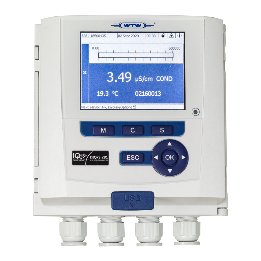
Page 46: Display
Operation DIQ/S 281 4.1.2 Display figure 4-2 Display 1 Name of the display indication (is skipped in the measured value display) 2 Name of the instrument (and series number, e.g. S281-20340001) 3 Date, time 4 User right (details see below) 5 Error symbol If the error symbol flashes, a new or unacknowledged error message is present in the log book that requires immediate action (see... - Page 47 DIQ/S 281 Operation Measured value The measured value display contains the following information: display figure 4-3 Display - measured value display 1 Consecutive numbering of the measured values 2 Main measured value 3 Adjoining measured value with unit 4 Series number of the sensor 5 Unit and parameter of the main measured value 6 User right (details see above) Special displays...
-
Page 48: Keys
Operation DIQ/S 281 4.1.3 Keys Function <M> Display measured values <C> Start calibration of the IQ sensor shown in the measured value display <S> Open the Einstellungen/Settings menu <ESC> Change to the higher menu levels or abort entries without storing them <OK>... -
Page 49: Navigating In Menus, Lists And Tables
DIQ/S 281 Operation Short operating instructions are given in the help lines on the dis- play. Examples of the operating principles are given below: Navigation in menus, lists and tables (see chapter 4.2.1) Entering text and numerical values (see chapter 4.2.2) 4.2.1 Navigating in menus, lists and tables <S>... -
Page 50: Entering Texts Or Numerals
Operation DIQ/S 281 4.2.2 Entering texts or numerals You can assign names to the outputs. Example: <S> Open the Einstellungen/Settings menu with < > Select the Edit list of outputs menu item with <OK> Confirm the Edit list of outputs menu item with The Edit list of outputs display opens. - Page 51 DIQ/S 281 Operation figure 4-6 Edit list of outputs The following letters, numerals and special characters can be entered: AaBb..Zz0..9µ%&/()+-=><!?_ °. < > Select a letter or numeral with <OK> Confirm the letter with The character appears behind the last letter. figure 4-7 Edit list of outputs ba77244d01...
-
Page 52: Access To The Diq/S 28X With Active Access Control
Operation DIQ/S 281 Add a new character < > Select the character to be added with and confirm with <OK> Delete the last character < > <OK> Select the character with and confirm with Adopt the name <... -
Page 53: Display Of Current Measured Values
DIQ/S 281 Operation Further details on access control (see section 5.3) Display of current measured values The measured value is displayed numerically and as a rod. figure 4-8 Measured value Messages and log book The DIQ/S 28X Universal Transmitter continuously monitors the status of the entire system. -
Page 54: Log Book
Operation DIQ/S 281 In the case of errors, immediately open the detailed message text in the log book and perform the recommended actions. If the actions have been performed, mark the message as read (see section 4.5.3). 4.5.2 Log book The log book is a list with all the messages from all modules. - Page 55 DIQ/S 281 Operation The system provides the following log books: Log book of entire system: List of all messages from all modules Log book of sensor: List of all messages of the IQ sensor. There is a detailed message text for each message of a module that is ready for operation.
-
Page 56: Viewing Detailed Message Texts
Operation DIQ/S 281 Example: The "171" module (Universal Transmitter DIQ/S 28X) sends a message with the Message code short message form "II2". II2171 This is an info message (I) of the type Installation (I) with the type number (2). The detailed message text of the short form message (II2) can be found in the log book and in the operating manual of the component that sent it. -
Page 57: Acknowledge All Messages
DIQ/S 281 Operation figure 4-10 Log book of entire system <OK> Acknowledge the message with . A checkmark appears in the log book entry. <ESC> Exit the message text with Acknowledgment of a new message text in the log book marks the message as read. -
Page 58: Calibration Data
Operation DIQ/S 281 <S> Open the Einstellungen/Settings menu with < > Using , select the menu item, Service and confirm with <OK> < > Using , select the menu item, Acknowledge all messages <OK> and confirm with . A security prompt opens. <... -
Page 59: Calibration History
DIQ/S 281 Operation < > Select and open a calibration entry (ECxxxx or ICxxxx) with <OK> <M> <ESC> Exit the Log book of sensor window with 4.6.2 Calibration history The calibration history contains the detailed calibration data of the last calibra- tions. -
Page 60: General Course When Calibrating, Cleaning, Servicing Or Repairing An Iq Sensor
Operation DIQ/S 281 with sensor info figure 4-11 List of all components <M> <ESC> Exit the Status of output channels window with General course when calibrating, cleaning, servicing or repairing an IQ sensor When an IQ sensor is calibrated, cleaned, serviced or repaired, the mainte- nance condition for the IQ sensor should always be switched on. -
Page 61: Maintenance Condition Of Iq Sensors
DIQ/S 281 Operation Outlet Switch on the maintenance condition for the IQ sensor (see section 4.8.2). The display of the sensor in the measured value display flashes. Pull the sensor out of the sample. Perform the calibration in the laboratory, cleaning, maintenance or repair (removing and replacing) of the sensor (about these topics, see the component operating manual of the corresponding sensor). -
Page 62: Switching On The Maintenance Condition
Operation DIQ/S 281 Maintenance Sensor condition cleaning ON manual Measured value Measured value display Measured value active display display The measured value Clean flashes stops flashing. The measured value Maintenance flashes. Sensor condition cleaning OFF manual (automatic sequence) Display mesage Switch on the maintenace condition... -
Page 63: Switching Off The Maintenance Condition
DIQ/S 281 Operation <M> Call up the measured value display with The display of the sensor in the measured value display flashes. Subsequently, perform the cleaning, maintenance or repair work (removal and replacement). When you have finished calibrating, cleaning, servicing or repairing the sensor, switch off the maintenance condition manually (see section 4.8.3). -
Page 64: Info On Software Versions
Operation DIQ/S 281 4.10 Info on software versions The system informs you of the current versions of the software of the individual components. <M> Call up the measured value display with <S> Open the Einstellungen/Settings menu with < > Using ... - Page 65 DIQ/S 281 Operation The instrument software is transferred to the DIQ/S 28X via the USB port and with the aid of a USB memory device. A Software-Update does not change the measurement settings, measurement data and calibration data. You can view the software versions of all components in the dialog box, List of all components (see section 4.10).
-
Page 66: Settings/Setup
Settings/setup DIQ/S 281 Settings/setup Selecting the language A list shows all the available system languages. <S> Open the Einstellungen/Settings menu with < > <OK> Using , select and confirm the menu item, Language. The Language display opens. figure 5-1 Language <... -
Page 67: Access Control
DIQ/S 281 Settings/setup Illumination brightness Illumination brightness (standby) figure 5-2 Terminal settings Setting Selection/Val- Explanation AaBb..Zz User-defined character string with max. 15 Terminal name 0..9µ%&/() characters +-=><!?_ ° Auto Brightness of the display during operation of the Illumination brightness 0 ... -
Page 68: Activating The Access Control
Settings/setup DIQ/S 281 Access to the system with active access control (see section 4.3). Default settings Access control is switched off in the delivery condition. Every user can carry out all functions. Saving the If access control for the DIQ/S 28X is active and the administrator password is password lost, rapid administrator access to the DIQ/S 28X is no longer possible. - Page 69 DIQ/S 281 Settings/setup Validity User right Symbol User rights Access only with password Maintenance Calibration View measured values Without instrument block: Viewer Access without password With instrument block: Access only with password View measured values For the instru- Instrument ...
-
Page 70: Activating The Instrument Block
Settings/setup DIQ/S 281 < > <OK> Press to select an user right and confirm with If necessary, change the password in the selection dialog and/or save the password to a connected USB memory. Note passwords. For reasons of safety the administrator password at least should be saved in such a way that it can be accessed in an emergency. -
Page 71: Electronic Key
DIQ/S 281 Settings/setup < > <OK> Using , select OK and confirm with The settings are adopted. The Access control dialog window is still open. The current passwords are visible. Switching off the <OK> Press to open the Display/Options / Change user rights menu. instrument block The password query is displayed. -
Page 72: Access To The Diq/S 28X With Active Access Control
Settings/setup DIQ/S 281 < > Press to select an authorization level and confirm with <OK> < > Using , select the menu item, Save access code on USB <OK> memory and confirm with The password for the selected authorization level is saved to the USB memory device. - Page 73 DIQ/S 281 Settings/setup menu and enhanced sensor functions: All sensors Measured value display Settings / Einstellungen Settings of sensors Column, measuring range Sensor Note : links are deleted Sensor setting menu figure 5-4 Calling up the sensor settings If the measuring mode or measured parameter are changed, a link of the sensor with a relay is erased! Details on sensor settings are given in the operating manual for the IQ sensor.
-
Page 74: Editing The List Of Outputs
Settings/setup DIQ/S 281 Editing the list of outputs The Edit list of outputs display provides an overview of all outputs, links and inactive datasets. Linking outputs and sensors (seesection 6.4). For the easier identification of the outputs, you can assign an individual name to each output in the Edit list of outputs display. -
Page 75: Alarm Settings
DIQ/S 281 Settings/setup figure 5-6 Edit list of outputs -> enter a name Alarm settings 5.6.1 General information Under this menu item you can specify reactions on certain alarm events. An alarm event is when a certain measured value (limiting value) of a sensor is exceeded or undercut. - Page 76 Settings/setup DIQ/S 281 figure 5-7 Alarm settings -> Alarm link overview The sensor number and serial number is displayed in the Sensor column. < > Select an alarm A01 to AXX to be edited with . To set up a new alarm without entry select in the Sensor column.
- Page 77 DIQ/S 281 Settings/setup figure 5-9 Set alarm link Edit the setting table. The required operating steps are described in detail in section 4.2 G ENERAL OPERATING PRINCIPLES Alarm links setting table Menu item Selection/Values Explanations Main variable Main variable designates the actual Measured variable measured parameter of the sensor (e.g.
-
Page 78: Alarm Output To Display
Settings/setup DIQ/S 281 Menu item Selection/Values Explanations Dxx / .../Ry Opens a list with all relay outputs where Relay output the Alarm contact is set. Dxx: number of the output module .../Ry: relay output channel Here you can select a relay output. When No relay output the alarm event occurs, it carries out the specified action (Open or Close). -
Page 79: Alarm Output As Relay Action
DIQ/S 281 Settings/setup <M> Pressing hides the alarm messages and switches to the measured value display. After one minute the alarm messages appear again if what caused them is still present. 5.6.4 Alarm output as relay action The relay outputs of the DIQ/S 28X can be configured so a relay action is trig- gered when an alarm event occurs (Open or Close). -
Page 80: Location Altitude / Average Air Pressure
Settings/setup DIQ/S 281 figure 5-11 Date/Time < > <OK> Press to select and confirm a number. The next field is highlighted, e.g. Month. Complete the entries on the display Date/Time. The clock in the DIQ/S 28X bridges periods of power failure of up to several hours. -
Page 81: Function Code
DIQ/S 281 Settings/setup figure 5-12 Location altitude/Air pressure < > Press to select Set altitude of location or Set air pressure <OK> and confirm with < > Press to change the values for Loc. altitude: or Air pressure: <OK>... -
Page 82: Outputs
Outputs DIQ/S 281 Outputs Outputs of the DIQ/S 281 Functioning of the outputs Relay outputs work as openers or closers. Current outputs provide a current depending on the measured value. On the DIQ/281 you can do the following: ... -
Page 83: Basic Information On Relay Functions
DIQ/S 281 Outputs Basic information on relay functions This chapter describes general basic information concerning the following relay functions: Monitoring (see section 6.2.1) Limit indicator (see section 6.2.2) Proportional output (see section 6.2.3) 6.2.1 Monitoring When using a relay for monitoring, a relay action (Open, Close) occurs when certain states occur. -
Page 84: Proportional Output
Outputs DIQ/S 281 Monitoring limit- Measured ing values using value one or two relays Relay 1 Hysteresis UL Hysteresis LL Relay 2 Time 1 Upper limit value (relay 1) exceeded 2 Selected switching delay t1 for relay 1 1 expired Relay 1 switches 3 Hysteresis for upper limiting value (relay 1) undercut 4 Selected switching delay t1 for relay 1 1 expired... - Page 85 DIQ/S 281 Outputs Proportional outputs can be used in the following way: Output with one relay: An output range is defined with a Start value and an End value. No output takes place above and below the output range (see page 85). ...
- Page 86 Outputs DIQ/S 281 Pulse width output The output of the pulse width is used, e.g. for controlling valves. Pulse-width regulation changes the duration of operation (t ) of the output sig- nal. Depending on the position of the measured value in the proportional range, the relay is operated for a longer or shorter period.
- Page 87 DIQ/S 281 Outputs switched more often or less often. Relay t = 0.3 s Time [s] figure 6-5 Relay output of frequency output While the selected switching duration (t = 0.3 s) always remains con- stant, the switching frequency at which the relay switches changes depending on the measured value.
- Page 88 Outputs DIQ/S 281 Switching frequency f or Pulse width Max. Min. Measured value Start value End value figure 6-6 Positive characteristic curve Switching frequency f or Pulse width Max. Min. Measured value End value Start value figure 6-7 Negative characteristic curve ba77244d01 08/2020...
- Page 89 DIQ/S 281 Outputs The proportional output range begins above the initial value. If the proportional Positive character- range is undercut or exceeded, the selected behavior comes into force. istic curve Pulse width v [%] Cycle duration T Of f Proportional band Time Measured value 2...
- Page 90 Outputs DIQ/S 281 The proportional output range begins below the initial value. If the proportional Negative charac- range is undercut or exceeded, the selected behavior comes into force. teristic curve Pulse width v [%] Cycle duration T Of f Proportional band Time Measured value 1...
-
Page 91: Entering / Editing The Name Of An Output
DIQ/S 281 Outputs Entering / editing the name of an output For easier identification of the outputs, an individual name can be given to each output in the Edit list of outputs overview. <S> Open the Einstellungen/Settings menu with < >... -
Page 92: Linking The Output With A Sensor
Outputs DIQ/S 281 Linking the output with a sensor <S> Open the Einstellungen/Settings menu with < > <OK> Using , select and confirm the menu item, System settings -> Settings of outputs and links. The Settings of outputs and links display opens. <... -
Page 93: Deleting A Link With An Output
DIQ/S 281 Outputs Deleting a link with an output If a link between a current or relay output and a sensor is no longer required, you can erase the link. <S> Open the Einstellungen/Settings menu with < > <OK> Using , select and confirm the menu item, System settings ->... -
Page 94: Setting The Relay Outputs
Outputs DIQ/S 281 Setting the relay outputs <M> Call up the measured value display with <S> Open the Einstellungen/Settings menu with < > Using , highlight the menu item, Settings of outputs and <OK> links, and confirm with . The Settings of outputs and links display appears. -
Page 95: Relay Action
DIQ/S 281 Outputs Function Description The relay output is not used. No function see section 6.6.2 System monitoring see section 6.6.3 Sensor monitoring see section 6.6.4 Limit indicator see section 6.6.5 Frequency controller see section 6.6.6 Pulse-width output see section 6.6.7 Cleaning see section 6.6.8 Manual control... -
Page 96: System Monitoring
Outputs DIQ/S 281 6.6.2 System monitoring Function The System monitoring function enables the monitoring of system errors. In order to set up the System monitoring function for a relay output, the relay output must not be linked with a sensor (see section 6.4). It can be used to monitor the following system errors. -
Page 97: Sensor Monitoring
DIQ/S 281 Outputs 6.6.3 Sensor monitoring Function The Sensor monitoring function enables the monitoring of sensor errors and the maintenance condition. In order to set up the Sensor monitoring function for a relay output, the relay out- put must be linked with the sensor (see section 6.4). Settings Setting Selection... -
Page 98: Limit Indicator
Outputs DIQ/S 281 6.6.4 Limit indicator Function The characteristic of the limit indicator is laid down in the Limit value UL, Limit value LL, Hysteresis UL and Hysteresis LL settings. The fundamentals of the function are described in the introductory chapter (see section 6.2.2). In order to set up the Limit indicator function for a relay output, the relay output must be linked with a sensor (see section 6.4). - Page 99 DIQ/S 281 Outputs the function are described in the introductory chapter (see section 6.2.3). In order to set up the Frequency controller function for a relay output, the relay output must be linked with a sensor (see section 6.4). Settings Setting Selection/Values Explanation...
-
Page 100: Pulse-Width Output
Outputs DIQ/S 281 6.6.6 Pulse-width output Function The characteristic of the pulse width output is laid down in the Start value, End value, Pulse width (v) min. and Pulse width (v) max. settings. The fundamentals of the function are described in the introductory chapter (see section 6.2.3). In order to set up the Pulse-width output function for a relay output, the relay output must be linked with a sensor (see section 6.4). - Page 101 DIQ/S 281 Outputs In order to set up the Cleaning function for a relay output, the relay output must be linked with a sensor (see section 6.4). The relay of the combination output module assigned always works as a closer. The cleaning cycle consists of Cleaning duration and Adjustment time.
- Page 102 Outputs DIQ/S 281 * With short cleaning intervals, the adjustable values for the Cleaning duration and Adjustment time are limited. The following values apply: Cleaning interval Cleaning duration Adjustment time ≤ max. 60 s max. 120 s 10 min ≤ max.
- Page 103 DIQ/S 281 Outputs t1a t1b relay condition closed open 00:00 04:00 12:00 20:00 24:00 Time 1 Reference time Begin of a cleaning cycle (t1) Begin of the specified Cleaning duration (t1a) 2 End of the specified Cleaning duration (t1a) Begin of the specified Adjustment time (t1b) 3 End of the specified Adjustment time (t1b) End of the cleaning cycle (t1) 4 Reference time ±...
-
Page 104: Manual Control
Outputs DIQ/S 281 The next cleaning cycle will be performed at the time set up. In case of a power failure, all relays open. The cleaning cycle is canceled. The outputs linked with the sensor change to the non- active condition (see section 6.9.2). As soon as the power is avail- able, the outputs are released again. -
Page 105: Setting The Current Outputs
DIQ/S 281 Outputs Setting the current outputs <M> Call up the measured value display with <S> Open the Einstellungen/Settings menu with < > Using , highlight the menu item, Settings of outputs and <OK> links, and confirm with . The Settings of outputs and links display appears. -
Page 106: Recorder
Outputs DIQ/S 281 < > <OK> Using , highlight and confirm Save and quit. The new settings are stored. 6.7.1 Recorder Function The measured values of the linked sensor at the current output are set up as cur- rent intensity in the Recorder application. The output of measured values is laid down in the Recorder type, Start value and End value settings. -
Page 107: Pid Controller
DIQ/S 281 Outputs The current at the output remains Unchanged unchanged. 6.7.2 PID controller Function The PID controller function can use an output as a controller output. The regu- lator can be configured as a Proportional regulator with switchable Integral and Differential regulator parts (PID Controller). - Page 108 Outputs DIQ/S 281 By activating or deactivating the Integral (ti) and Differential (td) controller part, the following controller types can be configured: Regulator type td [s] ti [s] P controller 1 to 9999 PI controller 1 to 9999 PD controller 1 to 9999 1 to 9999 PID controller...
- Page 109 DIQ/S 281 Outputs 8 mA Imin 14 mA Imax 12 mA 0 s (no I algorithm) 0 s (no D algorithm) The control parameters result in the following (negative) characteristic curve: Current I [mA] Imax Imin Measured value [mg/l] Nominal value figure 6-18 Characteristic curve for application example ba77244d01 08/2020...
- Page 110 Outputs DIQ/S 281 The controller works with the following amplification: mg/l mg/l Within the proportional range an increase of the concentration by 1 mg/l causes a reduction of the output current by 1 mA. If the measured con- centration is 5 mg/l, for example, 11 mA is output: ⋅...
-
Page 111: Fixed Current Value
DIQ/S 281 Outputs Setting Selection/Values Explanation 0 ... 20 mA Current value on the output if the measured value equals the Nominal value 0 ... 9999 s Hold-back time: Integral part of the controller (0 = not effective) 0 ... 9999 s Reset time: Differential part of the controller... -
Page 112: Checking The Condition Of The Outputs
Outputs DIQ/S 281 Checking the condition of the outputs This function provides a simple overview of the conditions of all outputs of the combination output module (see section 4.7). For the relays, the displayed condition is open or closed. For the current outputs, the current value present at the outputs is displayed. Behavior of linked outputs 6.9.1 Behavior in case of error For linked relay outputs or current outputs, you can determine the behavior of... -
Page 113: Behavior In Non-Operative Condition
DIQ/S 281 Outputs 6.9.2 Behavior in non-operative condition An output is non-operative when no function is activated for the output. An output becomes non-operative in case of Power failure (As soon as the supply voltage is sufficient again, the non-operative condition of the outputs ends. -
Page 114: Maintenance And Cleaning
Maintenance and cleaning DIQ/S 281 Maintenance and cleaning Maintenance Maintenance Component Maintenance activities IQ sensors Depending on the type of sensor (see the component operating manual of the sensor) No maintenance required DIQ modules Cleaning Clean components mounted in the open of gross contamination as necessary. DIQ modules We recommend cleaning the worst of the dirt on the enclosure and the area directly around it each time before opening in order to prevent contamination... -
Page 115: What To Do If
DIQ/S 281 What to do if ... What to do if ... Information on errors Log book The DIQ/S 28X system performs a comprehensive cyclical self test during oper- ation. While doing so, the system identifies all states that deviate from normal operation and enters corresponding messages in the log book (information or error message). -
Page 116: Replacing System Components
What to do if ... DIQ/S 281 Replacing system components It is always possible to replace components and assign a substitute if the software state of the substitute component is as high as or higher than the software version of the original component. 8.3.1 Replacing passive components Passive components include all components that the universal transmitter can- not recognize. - Page 117 DIQ/S 281 What to do if ... When an IQ sensor is connected to the system, the system checks whether an inactive dataset is available for the sensor type. If an inactive dataset for the sensor type is available, the inactive dataset is auto- matically assigned to the newly connected sensor.
-
Page 118: Technical Data
Technical data DIQ/S 281 Technical data DIQ/S 281 Dimensions Lateral view: Front view: DIQ/S 281-CR2 144,0 52,2 68,0 DIQ/S 281 UNIVERSAL TRANSMITTER 11,0 16,5 Rear view: 115,0 70,0 137,0 figure 9-1 Dimension drawing of the DIQ/S 281 (dimensions in mm) Mechanical Enclosure material Polycarbonate with 20 % glass fiber... - Page 119 DIQ/S 281 Technical data Ambient Temperature conditions Mounting/installa- + 5 °C ... + 40 °C (+ 41 ... +104 °F) tion/maintenance Operation - 20 °C ... + 55 °C (- 4 ... + 131 °F) Storage - 25 °C ... + 65 °C (- 13 ... + 149 °F) Relative humidity ≤...
- Page 120 Technical data DIQ/S 281 Electrical The electrical connections are inside the housing. connections Assignment of the terminal strips: See section 3.12. DIQ/S 28X-CR2 Relay Output Galvanically separated (2 x) Max. switching voltage 240 VAC or 24 VDC Max. switching current 2 A (AC and DC) Installation require- Fuse rating on the operator side: max.
- Page 121 DIQ/S 281 Technical data Cable glands Suitable for cable diam- 4.5 ... 10 mm or 7 ... 13 mm eter EMC product and EN 61326 EMC requirements for electrical resources for con- system charac- trol technology and laboratory use teristics –...
-
Page 122: Diq/Jb
Technical data DIQ/S 281 DIQ/JB Dimensions DIQ/JB figure 9-2 Dimension drawing of DIQ/JB (dimensions in mm) Mechanical Enclosure material Polystyrene structure Weight Approx. 0.2 kg Type of protection IP 66 (not suitable for conduit connection) Electrical (7 passive, potential free terminals for connections line extension or branching) Connecting... -
Page 123: Diq/Chv
DIQ/S 281 Technical data DIQ/CHV Dimensions DIQ/CHV figure 9-3 Dimension drawing of DIQ/CHV (dimensions in mm) Mechanical Enclosure material Polystyrene structure Weight Approx. 0.3 kg Type of protection IP 66 (not suitable for conduit connection) Electrical 1 x valve switching contact connections ... -
Page 124: Space Required By Mounted Components
Technical data DIQ/S 281 NOTE The valve may only be operated with the auxiliary voltage of the DIQ/S 28X uni- versal transmitter. Compressed air Required air quality Dry, free of dust and oil Operating pressure Max. 7x10 Pa (7 bar) absolute Connections on the DIQ/CHV 6 mm hose nozzles Space required by mounted components... -
Page 125: Accessories And Options
DIQ/S 281 Accessories and options Accessories and options Description Model Order no. IQ S cable - please specify required length in m SNCIQ 480046 ENSOR when ordering SNCIQ/UG 480047 IQ sensor connection cable 1.5 m SACIQ-1.5 480040 7.0 m SACIQ-7.0 480042 15.0 m SACIQ-15.0... -
Page 126: Messages
Messages DIQ/S 281 Messages 11.1 Explanation of the message codes The log book contains a list with all the messages from all modules. Each message consists of message code, date and time. You can obtain more detailed information by opening the full message text (see section 4.5). The full message text comes from the component that has triggered the message. -
Page 127: Informative Messages
DIQ/S 281 Messages Message code Message text EI8171 Connection to the component instable * Check installation and cable lengths, Follow installation instructions * Set SN terminator switch acc. to operating manual * Check environmental effects * Component defective, contact service EI9171 Power failure occurred * Check date and time and, if necessary, adjust them... - Page 128 Messages DIQ/S 281 ba77244e01 08/2020...
-
Page 129: Index
DIQ/S 28X Index Index Access control ..........67 Keys ............48 Air pressure ..........80 Ambient conditions ........119 Arrow keys .. 48, 83, 86, 92, 95, 97, 102, 104, Language ............66 111, ............113 Lightning protection Auxiliary voltage External protective measures ....13 Terminal strip ........ - Page 130 DIQ/S 28X Index Air pressure .......... 80 Alarms ..........75 Date ............79 Site altitude ........... 80 Terminal ..........66 Time ............. 79 Site altitude ..........80 Software status Of all components ........ 64 Special user qualifications ......11 Start checklist ..........38 Starting the system ........
- Page 132 For more information on how Xylem can help you, go to xyleminc.com. ® Service and Returns: Xylem Analytics Germany Sales GmbH &...
Need help?
Do you have a question about the WTW DIQ/S 281 and is the answer not in the manual?
Questions and answers