
Related Manuals for Xylem MJK Oxix


Summary of Contents for Xylem MJK Oxix
- Page 1 Dissolved Oxygen Transmitter Dissolved Oxygen Transmitter Installation and User Manual GB Oxix Manual 1209 FW: 841013-009, 846001-002, 841513-009...
- Page 2 Dissolved Oxygen Transmitter CE CERTIFICATE OF CONFORMITY This product complies with the requirements concerning electromagnetic compatibility (EMC) stipulated in Council directive no. 89/336/EEC of 3rd may 1989, alteret at directive no. 92/31/ EEC, on the approximation of the laws of the member states relating to electromagnetic compat- ibility.
-
Page 3: Table Of Contents
Dissolved Oxygen Transmitter Table of Contents 1. Introduction Operating Principles ........... .10 Features . - Page 4 Dissolved Oxygen Transmitter 8. Startup Initial Checks before Power-up ..........37 Initial Power-up .
- Page 5 Dissolved Oxygen Transmitter Appendix A. Pop-up and Error Messages Appendix B. MJK-Field Link Software Important Notes! ............89 A.
- Page 6 Dissolved Oxygen Transmitter This page intentionally left blank GB Oxix Manual 1209 FW: 841013-009, 846001-002, 841513-009...
-
Page 7: Introduction
Dissolved Oxygen Transmitter 1. Introduction Thank you for choosing the MJK Oxix Dissolved Oxygen Transmitter. We ® have done our utmost to design and manufacture a quality transmitter that satisfies your requirements: • High performance optical sensor • No calibration • No spareparts needed in sensor's 10 year lifetime • Air or water jet cleaning system is standard • Measurements not affected by sunlight or dry environment • Large, easy-to-read display with trend curve capability... - Page 8 Dissolved Oxygen Transmitter About this Manual This manual is divided into one table of contents, eleven chapters, five appen- dices, four continuous menu overview flow charts and one index. 1. Introduction Contains a presentation of the Oxix Dissolved Oxygen Transmitter, the ® structure of this manual, the operating principles and the top features. 2. Safety, Repair and Product Identification Provide answers to issues regarding safety, mounting, repair, restrictions and product identification.
- Page 9 Dissolved Oxygen Transmitter Appendix A. Pop-up Events / Error Messages Lists possible pop-up messages, explains their meaning and offer solutions to error conditions. Appendix B. MJK-Field Link Software Upgrade Describes in detail how to utilise the unique and intuitive MJK-Field Link software program to upload new display and converter firmware versions. Appendix C. Front Panel Cut-out Drawing A 1:1 scale drawing of the front panel outline and cut-out area for installa- tion and mounting purposes.
-
Page 10: Operating Principles
Dissolved Oxygen Transmitter Operating Principles The MJK Oxix Dissolved Oxygen Transmitter is designed for measuring the ® oxygen contents in open tanks exposed to sunlight, wells and closed contain- ers. The Oxix sensor function is based on the fluorescence principle and does ®... -
Page 11: Features
Dissolved Oxygen Transmitter Features Flexible Installation MJK’s modular design allows up to 300 meters (950ft.) between the sensor and the converter, and the Display Unit can be mounted up to 1000 m (3000 ft.) from the signal converter with ordinary twisted wires. 1 pc. - Page 12 Dissolved Oxygen Transmitter Flexible In- and Outputs Transmitter has one 4-20 mA analogue output, two digital outputs Oxix ® for alarms or control, and one digital input for resetting alarms, batches, etc. User-definable Text Up to five lines of text and readings can be configured by the user. The graphic display is automatically adjusted to show the largest characters pos- sible.
-
Page 13: Safety, Repair And Product Identification
Dissolved Oxygen Transmitter 2. Safety, Repair and Product Identification Safety Instructions • Read this manual carefully. • Pay attention to the environment on the installation site. • Wear necessary protective equipment and follow all current safety regula- tions. • Oxix can invoke a start signal for dangerous machinery. Always ensure ®... - Page 14 Dissolved Oxygen Transmitter This page intentionally left blank GB Oxix Manual 1209 FW: 841013-009, 846001-002, 841513-009...
-
Page 15: Specifications And Order Numbers
Dissolved Oxygen Transmitter 3. Specifications and Order Numbers Specifications Oxix Transmitter ® Accuracy +/- 0,1% of reading Measuring input RS 485 One active 4 - 20 mA, galvanically isolated (max. load 800 W) Analog output One voltage-free electromechanical relay (max. 50 V DC / 1 A) Digital outputs One optically isolated MOSFET relay (max. - Page 16 Dissolved Oxygen Transmitter Oxix Sensor ® 0 - 30.0 mg/l or ppm (parts per million) Dissolved oxygen saturated 0 - 120 % Measurement principle Optical, near infra-red fluorescence (l = 475 nm, I = 600 nm) Sensor check Automatic self-diagnostics Pressure 6 bar (100 psi) Materials Boby and Head: PU, PVC, silicone, epoxy and stainless steel 316 SS Optical lens: Sapphire...
-
Page 17: Order Numbers
Dissolved Oxygen Transmitter Order Numbers Oxix Converters ® 206304 Oxix Converter w/ display, 10 - 30 V DC ® 206305 Oxix Converter w/ display, 230 / 115 V AC ® 206306 Converter w/ display, 24 V AC Oxix ® 206307 Oxix Converter without display, 10 - 30 V DC ®... - Page 18 Dissolved Oxygen Transmitter This page intentionally left blank GB Oxix Manual 1209 FW: 841013-009, 846001-002, 841513-009...
-
Page 19: Sensor Installation
Dissolved Oxygen Transmitter 4. Sensor Installation WARNING! The Oxix transmitter must not be powered until the transmitter is ® correctly mounted and connected! WARNING! Connections to the Oxix transmitter must not be disconnected while ® the transmitter is powered. Important! To ensure safe and optimal functionality of the Oxix transmitter, ®... -
Page 20: Physical Sensor Installation
Dissolved Oxygen Transmitter Physical Sensor Installation Preparation Select a position that can produce a valid and representative measuring value and provide sufficient space for physical cleaning of the sensor on a regular basis. Positioning the Sensor The positioning of the sensor is very application dependant. There are, how- ever, some "do"s and "don't"s that can be used as guidelines. -
Page 21: Sensor Calibration
Dissolved Oxygen Transmitter 5. Sensor Calibration The Oxix sensor is factory calibrated. No further calibration is required. ® Zero-point Calibration Check A zero-point calibration check may be carried out as described below. Required materials • 1 bucket • 1 measuring cup • 1 tablespoon •... - Page 22 Dissolved Oxygen Transmitter This page intentionally left blank GB Oxix Manual 1209 FW: 841013-009, 846001-002, 841513-009...
-
Page 23: Converter
Dissolved Oxygen Transmitter 6. Converter Electrical Mounting Warning! The Oxix converter/display unit must not be mounted in ® explosion hazardous areas! Loosen the four screws (positions indicated by arrows) and remove the dis- play unit to gain access to the terminals. Max. four MJK converters with Modbus can be connected to one display unit: Converter #1 Converter #4... -
Page 24: Power Supply
Dissolved Oxygen Transmitter Power Supply The flow converter must be supplied from a properly fused mains outlet, a 24 volt AC outlet, or a 10 - 30 V DC power supply/battery. Power Supply 230 V AC, 115 V AC or 24 V AC Power Supply 10 - 30 V DC Terminal Designation Terminal Designation Protective ground Protective ground 230 / 115 / 24 V AC neutral —... -
Page 25: Changing The Power Supply Voltage 230/115 V Ac
Dissolved Oxygen Transmitter Changing the Power Supply Voltage 230/115 V AC To change the input mains voltage from 230 V AC to 115 V AC (or vice versa) proceed as follows: 1. Loosen the four screws on the front and lift out the display (see also page 23). - Page 26 Dissolved Oxygen Transmitter 7. See on the following picture where two jumpers must be inserted for a 115 V AC configuration: 115 V AC dual jumper positions 8. Insert and solder 2 jumpers (wires) in the positions indicated by the black arrows. 9.
-
Page 27: Analogue Output
Dissolved Oxygen Transmitter Analogue Output The analogue output is an active output with a maximum load of 800Ω. Analogue Output Terminal Designation 4-20 mA 4-20 mA The analogue output can be programmed for indication of primary units. See details on page 53. Digital Output Oxix has two digital outputs - DO1 with an opto (light triggered) relay and ®... -
Page 28: Digital Input
Dissolved Oxygen Transmitter Digital Input Oxix has one digital input which can be activated with a voltage higher than ® 10 V DC and de-activated with a voltage lower than 5 V DC. Digital Input Terminal Designation Max. 30 V DC The digital input (DI) can be programmed for the following functions: start and pause cleaning function Solid curve See also application examples in Appendix E. -
Page 29: Converter Terminals
Dissolved Oxygen Transmitter Converter Terminals Max. four MJK converters with Modbus can be connected to one display unit: Converter #1 Converter #4 Display unit 2 wire 4 wire shielded cable. shielded cable. GND A Sensor supply Fuse 200 mA T C2 N02 -Display- -mA- -DI-... -
Page 30: Sensor And Mounting Kit / Connection Board Terminals
Dissolved Oxygen Transmitter Sensor and Mounting Kit / Connection Board Terminals Important!: Make sure the right wiring indication label is fitted below the terminal block (label indicated by arrow). The label must clearly be marked Oxix ® Wrong wiring may cause sensor destruction ! Connect the sensor wires to the Oxix converter with the wires coming from ®... -
Page 31: System Configuration Examples
Dissolved Oxygen Transmitter 7. System Configuration Examples MJK Oxix transmitters share communication protocols with other MJK prod- ® ucts like the MJK Magflux flow meter and the MJK Connect data transmitter, ® and can also share display units. This section illustrates two configuration examples and includes cable connections and part numbers. -
Page 32: Magflux With Blind Lid And Oxix With Display Unit
Dissolved Oxygen Transmitter Magflux with Blind Lid and Oxix with Display Unit ® ® Configuration: Magflux flow sensor/converter with a blind lid connected ® to a Oxix transmitter with display unit ® Part numbers for this configuration: 2x7xxx MagFlux Flow Sensor ® 2x7791x MagFlux Connverter with blind lid... -
Page 33: Wiring Schematic #1
Dissolved Oxygen Transmitter Wiring Schematic #1 for " Magflux with Blind Lid and Oxix with Display Unit" from the opposite ® ® page (page 32). Max. four MJK converter can be connected to one Converter #1 Conv 2 wire shielded cable. GND A Oxix with Display Unit ®... -
Page 34: Susix ® With Blind Lid, Magflux ® With Blind Lid And A Remote Display
Dissolved Oxygen Transmitter SuSix with Blind Lid, Magflux with Blind Lid and a Re- ® ® mote Display Configuration: An Oxix transmitter with a blind lid connected to a Mag- ® flux flow sensor with a blind lid and common remote Display Unit. ®... -
Page 35: Wiring Schematic #2
Dissolved Oxygen Transmitter Wiring Schematic #2 for "Oxix with Blind Lid and a Magflux with Blind Lid connected to a com- ® ® mon wall mounted Display Unit" on the opposite page (page 34). Max. four MJK converte can be connected to one Converter #1 Conv Oxix... - Page 36 Dissolved Oxygen Transmitter This page intentionally left blank GB Oxix Manual 1209 FW: 841013-009, 846001-002, 841513-009...
-
Page 37: Startup
Dissolved Oxygen Transmitter 8. Startup Initial Checks before Power-up Before switching on power the following steps must be checked. 1. The local mains power supply voltage corresponds to the voltage printed on the identification label of the transmitter. 2. All electrical connections are made in accordance with the electrical con- nection diagram shown with special emphasis on the sensor connection described on page 30. -
Page 38: Display Read-Out, One Connected Unit
Dissolved Oxygen Transmitter Display Read-out, one connected unit All Oxix display read-outs are illustrated and described in this manual. ® Chapter 6. Oxix Menus (on page 41) gives a detailed description of the 5-line ® LCD screen displays shown during setup, confi guration and normal opera- tion. -
Page 39: Display Read-Out, Several Connected Units
SuSix1 SuSix1 Dissolved Oxygen Transmitter Meas. Meas. Display Read-out, several connected units Select Setup Sele When several MJK units are interconnected, for example an Oxix dissolved ® oxygen transmitter and a SuSix turbidity and suspended solids transmitter ® with different names and Modbus ID numbers, a "Display Overview Menu" is Main available at top level (press "Back"... - Page 40 Dissolved Oxygen Transmitter Contrast Adjustment Adjust the display contrast by pressing the two outmost keys simultaneously (indicated by the keys) and press the up/down keys as required. Save the new setting by pressing the two outmost keys simultaneously. System R eset You can reset and refresh all system displays and key combinations by press- ing all four keys simultaneously.
-
Page 41: Oxix ® Menus
Dissolved Oxygen Transmitter 9. Oxix Menus ® All the Oxix menus and sub menus are shown and described in the following ® sections. Continous overviews of the menu and sub-menu structures are presented at the end of this manual: • Converter Overview Menu (page 102) •... -
Page 42: Specify Main Screen
Oxygen % SAT splay Dissolved Oxygen Transmitter Select Set up Main Menu Specify Main Screen Specify main Screen The "Specify Main Screen" menu allows you to customize the Oxix® display Datalogger to suit your requirements. You can add and remove five available display lines Password and name/configure them individually. - Page 43 Dissolved Oxygen Transmitter Temperature The temperature may be displayed in degrees Celcius (ºC) or in degrees Fahrenheit (ºF). See also page 52. Clock Time and date The size of the display lines will automatically increase or decrease as the number of display lines is removed or added to maximize the field of view for the measured values GB Oxix Manual 1209 FW: 841013-009, 846001-002, 841513-009...
-
Page 44: Datalogger
Dissolved Oxygen Transmitter Datalogger Display Overview Menu Converter Overview Menu Oxix® provides a data logger with a capacity of approx. 20,000 entry points. See Appendix D on page for examples and descriptions of log Oxix1 91.9 % Oxix1 files. Susix1 578 mg/L The data logger operates after the FIFO principle (First In, First Out). - Page 45 Dissolved Oxygen Transmitter The data log contains: • Date • Time • Dissolved oxygen values In case of a power failure, the data logger continues when power returns. If more converters are connected to one Display Unit, each converter has its own individual log interval and can be sorted. All converters share the same memory of 20.000 entry points.
-
Page 46: Graph Display
Dissolved Oxygen Transmitter Graph Display The content of the Data Logger can displayed on the Display Unit by pressing the up/down keys, highlighting "Oxygen sat." and selecting "Graph" Oxix1 Oxygen 98 % Select Graph Oxix1 Oxygen 98 % Select Graph The Display Unit then shows the Graph screen. To return to the Main Menu display screen, select "esc"... -
Page 47: Password
Dissolved Oxygen Transmitter Display Overview Menu Converter Overview Menu Password Oxix1 91.9 % Oxix1 Susix1 578 mg/L A password provides (and prevents) access to all the settings in the Display and Converter unit. The code consists of a numeric 5-digit code between Oxygen % SAT 0 and 65535. - Page 48 Dissolved Oxygen Transmitter Activate/deactivate Write protection. Selecting "Activate" means that a password must be en- tered to change vital settings. "Deactivate" disables password protection. If your current password is lost or forgotten, the password protection can be overruled with the code "01750". Change password The present 5-digit password can be changed as required.
-
Page 49: Sensor Name
Dissolved Oxygen Transmitter Sensor Name A unique name and/or number, a function or a location can be assigned for a sensor (here: "Oxix1"). It is consequently shown on the main display with up to 4 display lines. Display Overview Menu Converter Overview Menu Oxix1 91.9 % Oxix1... - Page 50 Display setup Back Select Linie Dissolved Oxygen Transmitter Linie Linie Linie Sensor name Linie Back Sensor name Aeration Tank Inlet Not i Back Select > Sens Cloc 3. Press the up/down keys to change the highlighted character and then Back press > to proceed to the next character. 4.
-
Page 51: Converter Setup
Dissolved Oxygen Transmitter Display Overview Menu Converter Overview Menu Oxix1 91.9 % Oxix1 Converter Setup Susix1 578 mg/L "Converter setup" provides configuration options for calibration, alarms, units, Oxygen % SAT etc. See detailed descriptions in the following sections, and a continuous Back Select Display overview on page... -
Page 52: Averaging
Dissolved Oxygen Transmitter Averaging Converter setup To avoid unwanted fluctuations in the measurement reading, the "Averaging" options smoothes the measurements over a predefined period of time. This menu is for display only. Averaging Units mA output Averaging Units Cleaning High alarm D.O. Units Averaging Enab Low alarm... -
Page 53: Ma Output
Dissolved Oxygen Transmitter mA Output When a Oxix® is connected to a power supply for the first time, the mA out- put is automatically set to provide 4 mA at zero and 20 mA at the theoretical maximum value. Changes in the mA setting will not affect the relay output settings. Note: Both values can be set in the range 10 % to 120 %, making it possible to increase or decrease the mA signal. -
Page 54: Cleaning
Dissolved Oxygen Transmitter Cleaning only. Air or water jet cleaning can be defined based on local conditions. Cleaning mA output Enable mA output? Electro-mechanical relay Opto relay Not in use Back Select Back Select 4mA output Interval Use DI to clean 4 mA = 00.00 mg/l Clean now Maintenance... - Page 55 Dissolved Oxygen Transmitter A typical cleaning interval for aeration basins would be 2 hours (120 minutes). In colder climates, condensation may form and then freeze in the tubing. This can be prevented by setting the interval to 5 - 20 minutes. The cleaning time would typically be 30 seconds. The measurement delay (recovery time) may also be used to coordinate with other processes.
-
Page 56: High Alarm
Dissolved Oxygen Transmitter High alarm A set point can be set to trigger an alarm (here: a high alarm) and to activate one of two relays or simply to display the alarm on the display. High Alarm Electro-mechanical relay Opto relay Display only Not in use Back Select... -
Page 57: Low Alarm
Dissolved Oxygen Transmitter Low alarm A set point can be set to trigger an alarm (here: a low alarm) and to activate one of two relays or simply to display the alarm on the display. Low Alarm Electro-mechanical relay Opto relay Display only Not in use Back Select... -
Page 58: Sensor Error
Dissolved Oxygen Transmitter Sensor error Oxix has two digital outputs - DO1 with an opto (light triggered) relay and ® DO2 with an electro-mechanical relay. They can both be programmed for a sensor error, whenever the 4 - 20 mA range has been exceeded. Sensor error Electro-mechanical relay Opto relay... -
Page 59: Status
Dissolved Oxygen Transmitter Status The "Status" option provides an overview of the in- and output status. Status Factory setting Type pas DO 1 [ x ] Selected function Recover factory settings DO 1 [ \ ] Selected function Cancel [ ] Selected function Default mA output 10,234 mA... -
Page 60: Factory Settings
Dissolved Oxygen Transmitter A blinking backward slant (\) in a check box indicates that the input/output is in the process of being de-activated. Eventually the check box is cleared. An empty check box indicates a de-activated state. DO 1 [ X ] Selected function The selected function linked to digital output D01 is active (an "X" in the check box). -
Page 61: Service Menu - Digest
Back Back Back On Stock Autodetect sensor type Main supply frequency Back Select Dissolved Oxygen Transmitter Service Menu - Digest Set ac The "Service Menu" provides options intended for service personnel during installation, calibration, operation, monitoring and maintenance. Back Service menu Type password 00000 Back Select... -
Page 62: Service Menu - Detailed
Dissolved Oxygen Transmitter Service Menu - Detailed The "Service Menu", a submenu in "Converter setup", is intended for MJK and other authorized service personnel during installation, calibration, Sensor Data commissioning, operation, monitoring and maintenance. Sensor Calibration Converter SW. Version. Product data Converter setup Sensor data Reset Counter Time Internal meas. - Page 63 Dissolved Oxygen Transmitter Sensor data "Sensor data" displays the factory-assigned sensor serial number and Sensor Data the present sensor software version. Sensor Calibration Converter SW. Version. Product data Sensor data Sensor calibration Reset Counter Time Internal meas. & cal. Calibrate mA Sensor serial number Sensor calibration Test Primary value 30487...
- Page 64 Dissolved Oxygen Transmitter Converter SW ver. The converter software version and the bootload version are displayed. From that you can determine whether a software (firmware) upgrade is required or not. Converter SW version Product data Sensor calibration Converter 846001-002 Sensor calibration Product ID Reset Co int calibration 000000000000 System R...
- Page 65 Dissolved Oxygen Transmitter Product Data Key product data like ID, hardware type no., track no. and HW type no. are displayed. Converter SW version Product data Reset counter time Inter Converter 846001-002 Product ID Reset Counter Calibrate 000000000000 System Runtime 2304 Bootload 840020-002 Calibrate Since Reset 2304...
- Page 66 Dissolved Oxygen Transmitter Internal Meas. & Cal. Internal measurements and calibrations are for service personnel use only! The supply voltage (Vcc) and the reference voltage (Vref) can be viewed and adjusted. Reset counter time Internal meas. & cal. set Counter Calibrate Vcc stem Runtime 2304 Calibrate V_ref nce Reset 2304...
- Page 67 Dissolved Oxygen Transmitter Calibrate mA From this menu the mA reading can be calibrated against a multimeter. Calibrate mA Test primary value Current Set primary value Set fixed current - - - - mg/l Current Calib. current - - - - uA DAC zero current DAC top current Back Select...
- Page 68 Dissolved Oxygen Transmitter Test primary value "Test primary value" is for MJK service personnel use only. It can be set to for example 100% to test a state or condition for a given input value. Test primary value Read eventlog No Hour Event Extension Set primary value Modbus - - - - mg/l...
- Page 69 Dissolved Oxygen Transmitter Read Eventlog View the events within a certain time frame. Test primary value Read eventlog Communication log No Hour Event Extension Recover Set primary value Modbus Cancel - - - - mg/l Rx ok 4950 Back on Rx CRC error 4564 Sensor F Rx paritet error...
- Page 70 Dissolved Oxygen Transmitter Communication log View the Modbus and sensor communication logs. Primarily intended for fault detection. alue Read eventlog Communication log Back on stock Autod No Hour Event Extension Recover Factory Settings Autod Modbus Cancel Rx ok 4950 Back on Stock Not in us Rx CRC error 4564 Sensor Factory Reset...
- Page 71 Dissolved Oxygen Transmitter Autodetect sensor type The option can be toggled as required. "Use" is the factory default setting. Back on stock Autodetect sensor type Mains supply frequency Recover Factory Settings Autodetect sensor type Mains supply frequency Cancel 50 Hz 4950 Back on Stock Not in use 60 Hz 4564...
-
Page 72: Display Setup
Dissolved Oxygen Transmitter Display Overview Menu Converter Overview Menu Oxix1 91.9 % Oxix1 Display Setup Susix1 578 mg/L The "Display Setup" menu provides options for language, clock and factory settings, Modbus parameters and software version display. Oxygen % SAT Back Select Display Display setup 1. -
Page 73: Language
Dissolved Oxygen Transmitter Language Display setup The Oxix is installed with a language package, and (GB) English is the default ® language. Language Set Clock In the "Language" menu several national languages can be selected. Modbus Factory settings Display SW version Set Clock Language Back Select... -
Page 74: Set Clock
Dissolved Oxygen Transmitter Set clock The "Set clock" menu provides setting of the built-in clock and the time for- mat. Set Clock Language Language Time Format (GB) English 24 Hour (US) English AM/PM Dansk Deutsch Back Select Español Français Italiano Set Clock Nederlands Norsk 2006-01-08... -
Page 75: Modbus
Dissolved Oxygen Transmitter Modbus The Oxix is delivered with a standard Modbus RTU protocol, and up to four ® Oxix and/or MagFlux units can be connected for concurrent ,Connect ® ® ® operation. Factor Modbus Add device Cancel Change Device addresse Delete Log Remove Device Restore defau Change Display ID No. - Page 76 Dissolved Oxygen Transmitter Change device address To change each converter's device adress it is required that you connect the Display Unit to each converter one by one to change each converter's device address. If neglected, a conflict between the units will arise when the RS 485 serial loop is established.
-
Page 77: Factory Settings
Dissolved Oxygen Transmitter Factory settings The "Factory settings" menu provides log deletion and resetting to factory settings of the display unit. Factory settings Display SW version Cancel Display 841013-009 Delete Log Aug 15 2008 15:14:20 Restore default Language Language 841513-009 Restore factory setting Back Select Back... - Page 78 Dissolved Oxygen Transmitter This page intentionally left blank GB Oxix Manual 1209 FW: 841013-009, 846001-002, 841513-009...
-
Page 79: Mechanical Dimensions
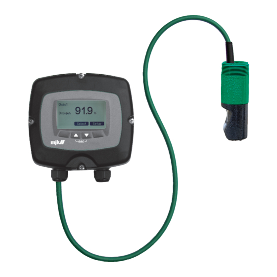
Dissolved Oxygen Transmitter 10. Mechanical Dimensions Sensor 1/4” tube 1/4” tube fitting Cable to Oxix 1 - 1/2” NPT Converter 130 mm (5”) 112 mm (4.2”) 48.5 mm (1.9”) Measuring element GB Oxix Manual 1209 FW: 841013-009, 846001-002, 841513-009... -
Page 80: Converter And Display Unit
Dissolved Oxygen Transmitter Converter and Display Unit GB Oxix Manual 1209 FW: 841013-009, 846001-002, 841513-009... -
Page 81: Immersion Fitting
Dissolved Oxygen Transmitter Immersion Fitting Oxix Immersion fitting ® order no. 155235 Wall bracket for extension Extension for universal bracket Universal bracket 1000 mm Oxix ® sensor GB Oxix Manual 1209 FW: 841013-009, 846001-002, 841513-009... - Page 82 Dissolved Oxygen Transmitter This page intentionally left blank GB Oxix Manual 1209 FW: 841013-009, 846001-002, 841513-009...
-
Page 83: Maintenance
Dissolved Oxygen Transmitter 11. Maintenance The Oxix sensor requires no maintenance as such. It may, however, be ® cleaned on a regular basis to maintain its maximum accuracy. In very slimy environments the built-in water or air jet function may be used with advantage. - Page 84 Dissolved Oxygen Transmitter This page intentionally left blank GB Oxix Manual 1209 FW: 841013-009, 846001-002, 841513-009...
- Page 85 Dissolved Oxygen Transmitter Appendix A. Pop-up and Error Messages Alarms Current overrange Alarm - The mA connection has exceeded the 4 - 20 mA range. For example 3,5 or 20,5 mA. Factory reset occurred Alarm - A factory reset has occured. Some settings have changed.
- Page 86 Dissolved Oxygen Transmitter Sensor Error - General sensor error that may also be transferred to a relay output. Contact MJK. Sensor communication Error - Modbus communication errrors nor- mally imply that a device has been moved, added, removed or has changed status in an illegal manner.
- Page 87 Dissolved Oxygen Transmitter Flash programming please Programming is in progress but not finished. wait Flash programming done Programming is finished. Flash crc error Cyclic redundancy check error. Unknown command flash Unvalid command issued. user text Flash address overrun A write error hos occured. File phase error Internal USB error.
- Page 88 Dissolved Oxygen Transmitter This page intentionally left blank GB Oxix Manual 1209 FW: 841013-009, 846001-002, 841513-009...
- Page 89 Dissolved Oxygen Transmitter Appendix B. MJK- Field Link Software The MJK-Field Link software package provides several utilities that will be described in detail on the following pages: • PC <-> Oxix transmitter interconnection ® • Saving log data • Display fi rmware upgrade •...
- Page 90 Dissolved Oxygen Transmitter 2. Unscrew the four screws that hold the Display Unit. 3. Lift out the Display Unit and connect a USB mini A/B cable to the mini USB female B connector on the rear of the front panel. 4. Connect the other end of the USB cable (max. 4.7 metres long) to the PC. 5.
- Page 91 Dissolved Oxygen Transmitter B. Save Log Data 1. Select "LogData" in the menu bar and click "Save Log to File". 2. Assign a file name, find the destination you want to save the file to, and click "Save". Consequently the file is saved, and the contents is displayed. C.
- Page 92 Dissolved Oxygen Transmitter 4. A "Searching for MJK-Field" dialogue box then appears and prompts for disconnecting and re-connecting the USB cable. Do as suggested and click OK. 5. Meanwhile the Oxix Display Unit restarts and displays the MJK logo, the ® new link status is displayed, and the Display Unit informs that the PC is once again connected.
- Page 93 Dissolved Oxygen Transmitter D. Upgrade Converter Firmware 1. Select "Firmware" in the menu bar and click "Converter". 2. Locate the "MJK Field FW" directory on the CD-ROM, select the "842xxx- xxx.hex" fi le (or similar) and click "Open". 3. Select the required Oxix (option 1, 2, 3 or 4) and click OK when the ®...
- Page 94 Dissolved Oxygen Transmitter E. Install/Add Languages All languages are removed during a display fi rmware upgrade. Consequently the required languages must be re-installed at this stage. 1. Select "File" in the menu bar and click "Languages". 2. A dialogue appears showing the currently installed languages (none follow- ing a fi rmware upgrade).
- Page 95 Dissolved Oxygen Transmitter Appendix C. Front Panel Cut-out Drawing Frontpanel outline The dotted line indicates the front panel outline and measures 155 x 145 mm. GB Oxix Manual 1209 FW: 841013-009, 846001-002, 841513-009...
- Page 96 Dissolved Oxygen Transmitter This page intentionally left blank GB Oxix Manual 1209 FW: 841013-009, 846001-002, 841513-009...
- Page 97 Dissolved Oxygen Transmitter Appendix D. Log Files The example log file shown below is the result of a CSV file from the converter (see "Save Log Data" procedure on page 91) having been opened in with Microsoft Excel spread sheet utility. ® ®...
- Page 98 Dissolved Oxygen Transmitter Index Converter ID (here four converters: 32, 33, 34 and 35) MB Address Modbus address (here: 1, 2, 3 and 4) SI unit according to the MJK unit codes (here: 246=NTU) Unit MJK Unit Codes Code no. Unit gallons per minute l/min litres per minute cubic meters per hour million gallons per day l/sec...
- Page 99 Dissolved Oxygen Transmitter Range Min Minimum value for graph The precision of the SI value Precision Column J The sensor name as entered by the operator. Time Date and time in Central European Standard Time (CEST) UTime The time in UNIX format. Number of seconds since January 1, 1970.
- Page 100 Dissolved Oxygen Transmitter To plot the log file's data, proceed as follows: 1. Start Excel and open the csv log file. 2. Sort by "Index", click the "Diagram Guide" tool in the toolbar and select the required curve or graph (see example on the next page). GB Oxix Manual 1209 FW: 841013-009, 846001-002, 841513-009...
- Page 101 Dissolved Oxygen Transmitter Appendix E. Input/Output Connections The digital in- and outputs, DI and DO, can be interconnected to external equipment to achieve a number of functions such as alarms, counter reset, flow direction indication, etc. The two schematics below illustrate a simplified mode of operation. MJK Field MagFlux com = common (-) External equipment...
- Page 102 Dissolved Oxygen Transmitter Appendix F. Quick Guide - Oxix Calibration Valid from firmware version 846003-001, a new calibration menu and method have been introduced in the Oxix converter. A factory calibration of both zero point and span has been made at delivery; these calibrations can be done independently of each other.
- Page 103 Dissolved Oxygen Transmitter Zero Point Calibration Zero point Calibration 0.00 mg/l Oxygen 0.10 mg/l Set actual measurement Back Select A zero point check or calibration is conducted as follows: • The sensor is set for a zero point solution. The current measurement is shown in line 2 (0.10mg/l in this example).
- Page 104 Dissolved Oxygen Transmitter Span Calibration Span Calibration 5.00 mg/l Oxygen 5.20 mg/l Set actual measurement Back Select window will create measurement vari- A span check or calibration is conduct- ations. ed as follows: Theory on making oxygen saturated • The sensor is measuring. The cur- solution rent measurement is shown in line 2 (5.20 mg/l in this example).
- Page 105 Dissolved Oxygen Transmitter Salinity Correction Factor Zero point Calibration 0.00 mg/l Oxygen 0.10 mg/l Set actual measurement Back Select Oxix in salinity applications A salinity correction factor is entered as follows: • The sensor is measuring. The current measurement is shown in line 2 (10.20 mg/l in this example).
- Page 106 Dissolved Oxygen Transmitter Restore Factory Calibration Zero point Calibration 0.00 mg/l Oxygen 0.10 mg/l Set actual measurement Back Select The sensor should be reset before calibrating zero point or span by using Reset Factory Calibration. This helps avoiding any errors in an existing calibration affecting the new calibration.
- Page 107 Dissolved Oxygen Transmitter Guide to Oxygen-free Solution for Checking Oxix D.O. Sensor Zero Point Method • Clean Oxix and its optical window thoroughly. ® • Dissolve 3 tablespoons Na2SO3 in 4 litres of tap water in an open con- tainer (bucket). • Stir for about 1 minute. •...
- Page 108 Dissolved Oxygen Transmitter Main Menu Overview Display Overview Menu Converter Overview Menu Oxix1 91.9 % Oxix1 Susix1 578 mg/L Oxygen % SAT Back Select Display Display setup Select Set up Main Menu Specify main Screen Datalogger Password Sensor name Converter setup Display setup Specify main Screen Back Select...
- Page 109 Dissolved Oxygen Transmitter Main Menu Overview (continued 2) Screen Datalogger Password Sensor name Conve Set log interval Login Sensor name Averaging Oxix 1 0020 sec Activate/deactivate Units Set new password mA output Cleaning Back Select > Back Select > Back Select High Alarm Low Alarm Sensor Error Status Factory setti...
- Page 110 Dissolved Oxygen Transmitter Main Menu Overview (continued 3) Converter setup Display setup Language Averaging Set Clock Units Modbus mA output Factory settings Cleaning > Display SW version High Alarm Low Alarm Back Select Sensor Error Status Factory settings Service menu word Back Select 0000 >...
- Page 111 Dissolved Oxygen Transmitter This page intentionally left blank GB Oxix Manual 1209 FW: 841013-009, 846001-002, 841513-009...
- Page 112 Dissolved Oxygen Transmitter Converter Setup Menu Overview Converter setup This menu is for display only. Averaging Units mA output Averaging Units Cleaning High alarm D.O. Units Averaging Enable mA o Low alarm 0001 sec Sensor error mg/l (from 1 sec to 120 min) Status Factory settings Back...
- Page 113 Dissolved Oxygen Transmitter Converter Setup Menu Overview (continued 2) display only. Cleaning mA output Enable mA output? Electro-mechanical relay Opto relay Not in use Back Select Back Select 4mA output Interval Use DI to clean e unit 4 mA = 00.00 mg/l Clean now Maintenance Back Select Back...
- Page 114 Dissolved Oxygen Transmitter Converter Setup Menu Overview (continued 3) clean Clean now Maintenance Clean now Maintenance Runtime 1000 hour Count Back Select Back Select Reset Maintenance 0100 ms > Back Select 05 sec GB Oxix Manual 1209 FW: 841013-009, 846001-002, 841513-009...
- Page 115 Dissolved Oxygen Transmitter Converter Setup Menu Overview (continued 4) High Alarm Electro-mechanical relay Opto relay Display only Not in use Back Select Opto relay Display only Electro-mechanical relay Electro-me On Setpoint On Setpoint On Setpoint On Setpoint 7,00 % 7,00 % 7,00 % Back Select >...
- Page 116 Dissolved Oxygen Transmitter Converter Setup Menu Overview (continued 5) Low Alarm Electro-mechanical relay Opto relay Display only Not in use Back Select only Electro-mechanical relay Opto relay Display only Electro-m On Setpoint On Setpoint On Setpoint Delay 5,50 % 5,50 % 5,50 % > Back Select >...
- Page 117 Dissolved Oxygen Transmitter Converter Setup Menu Overview (continued 6) Sensor error Electro-mechanical relay Opto relay Display only Not in use Back Select Opto relay Electro-mechanical relay Display only Delay Delay Delay 00100 ms 00100 ms 00100 ms > Back Select > Back Select > Back Select >...
- Page 118 Dissolved Oxygen Transmitter Converter Setup Menu Overview (continued 7) Status Factory setting Service menu Type password DO 1 [ x ] Selected function Recover factory settings 00000 DO 1 [ \ ] Selected function Cancel [ ] Selected function Default mA output 10,234 mA Force to SuSix Back Select >...
- Page 119 Dissolved Oxygen Transmitter This page intentionally left blank GB Oxix Manual 1209 FW: 841013-009, 846001-002, 841513-009...
- Page 120 Dissolved Oxygen Transmitter Service Menu Overview Sensor Data Sensor Calibration Converter SW. Version. Product data Sensor data Sensor calibration Reset Counter Time Internal meas. & cal. Calibrate mA Sensor serial number Sensor calibration Test Primary value 30487 1 point calibration Sensor software version 2 point calibration Read eventlog Comunication log...
- Page 121 Dissolved Oxygen Transmitter Service Menu Overview (continued 2) Converter SW version Product data Reset counter time calibration Converter 846001-002 calibration Product ID Reset Counter ation 000000000000 System Runtime Bootload 840020-002 ation Since Reset Runtime (days) elect Back Select > Back Back Select Product type no 2 point 00000206305 point...
- Page 122 Dissolved Oxygen Transmitter Service Menu Overview (continued 3) Reset counter time Internal meas. & cal. Reset Counter Calibrate Vcc 00000000 System Runtime 2304 Calibrate V_ref Since Reset 2304 Runtime (days) Back Select > Back Select 00206305 View Vcc View V_ref - - - - - - - - >...
- Page 123 Dissolved Oxygen Transmitter Service Menu Overview (continued 4) Calibrate mA Test primary value No Hour Current Set primary value Set fixed current - - - - mg/l Current Calib. current - - - - uA DAC zero current DAC top current Back Select > Back Back Select...
- Page 124 Dissolved Oxygen Transmitter Service Menu Overview (continued 5) y value Read eventlog Communication log Back on stock Autodet No Hour Event Extension Recover Factory Settings Autodet Modbus Cancel Rx ok 4950 mg/l Back on Stock Not in use Rx CRC error 4564 Sensor Factory Reset Rx paritet error 4545 >...
- Page 125 Dissolved Oxygen Transmitter Service Menu Overview (continued 6) nsor type Mains supply frequency nsor type Mains supply frequency 50 Hz 60 Hz Back Select GB Oxix Manual 1209 FW: 841013-009, 846001-002, 841513-009...
- Page 126 Dissolved Oxygen Transmitter Display Setup Menu Overview Display setup Language Set Clock Modbus Factory settings Display SW version Set Clock Language Back Select Language Time Format (GB) English 24 Hour (US) English AM/PM Dansk Deutsch Back Select Español Français Italiano Set Clock Nederlands Norsk 2006-01-08...
- Page 127 Dissolved Oxygen Transmitter Display Setup Menu Overview (continued 2) Modbus Add device Change Device addresse Remove Device Change Display ID No. Back Select 10:53:12 Add device Change device addresse Remove device Change Scanner Change device addresse Remove device Change > Device 1 Device 1 Back Back Select Back...
- Page 128 Dissolved Oxygen Transmitter Display Setup Menu Overview (continued 3) Factory settings Display SW version Cancel Display 841013-009 Delete Log Aug 15 2008 15:14:20 Restore default Language Language 841513-009 Restore factory setting Back Select Back evice Change display ID no. Change Display ID No. Back Select Number of Displays Back Select...
- Page 129 Dissolved Oxygen Transmitter GB Oxix Manual 1209 FW: 841013-009, 846001-002, 841513-009...
- Page 130 Dissolved Oxygen Transmitter GB Oxix Manual 1209 FW: 841013-009, 846001-002, 841513-009...
- Page 131 Dissolved Oxygen Transmitter Index dimensions ..........79 converter and display unit ....80 immersion fitting ........81 sensor ..........79 accessories ..........17 DI selected function ........60 accuracy ........... 15 display ..........11, 38 activate/deactivate ........48 one connected unit ......38 Add Device ..........
- Page 132 Dissolved Oxygen Transmitter jumper ............25 operating principles ........10 options Activate/Deactivate ......48 Add Device ......... 75 Autodetect sensor type ....... 71 keys, display ..........39 Averaging..........52 Back on Stock ........70 Calibrate mA ........67 Change controller ID ......76 Language ..........
- Page 133 Dissolved Oxygen Transmitter part number ..........13 temperature range ........15 password ..........47 terminals physical mounting ........13 converter ..........29 pop-up alarm ..........12 sensor ..........30 pop-up events ........... 85 Test primary value ........68 power consumption ........15 theory ............
- Page 134 SuSix are registrered trademarks of MJK Automation A/S. As our products are developed continuously, we reserve the © 2013 Xylem, Inc. 3.05 ES MagFlux Manual 02 2013 right to make any alterations without prior notice. GB Oxix Manual 1209...
Need help?
Do you have a question about the MJK Oxix and is the answer not in the manual?
Questions and answers