
Subscribe to Our Youtube Channel
Related Manuals for Xylem MJK SuSix


Summary of Contents for Xylem MJK SuSix
- Page 1 Turbidity and Suspended Solids Transmitter Turbidity and Suspended Solids Transmitter Installation and User Manual EN 5.10 SuSix Manual 2007 FW: 841013-005/843003-001...
- Page 2 Turbidity and Suspended Solids Transmitter CE CERTIFICATE OF CONFORMITY This product complies with the requirements concerning electromagnetic compatibility (EMC) stipulated in Council directive no. 89/336/EEC of 3rd may 1989, alteret at directive no. 92/31/EEC, on the approximation of the laws of the member states relating to electromag- netic compatibility.
-
Page 3: Table Of Contents
Turbidity and Suspended Solids Transmitter Table of Contents 1. Introduction About this Manual ........... 8 Operating Principles . - Page 4 Turbidity and Suspended Solids Transmitter 7. Startup Initial Checks ............43 Initial Measurement.
- Page 5 Turbidity and Suspended Solids Transmitter Functional Tests - Once a Year ......... 89 Electronics .
- Page 6 Turbidity and Suspended Solids Transmitter This page intentionally left blank EN 5.10 SuSix Manual 2007 FW: 841013-005/843003-001...
-
Page 7: Introduction
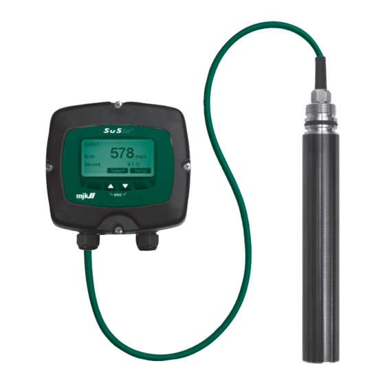
Turbidity and Suspended Solids Transmitter 1. Introduction Thank you for choosing the MJK SuSix Turbidity and Suspended Solids ® Transmitter. We have done our utmost to design and manufacture a quality transmitter that satisfies your requirements. The SuSix Transmitter, consisting of a sensor, a converter and a display, ®... - Page 8 Turbidity and Suspended Solids Transmitter EN 5.10 SuSix Manual 2007 FW: 841013-005/843003-001...
-
Page 9: About This Manual
This manual is divided into a table of contents, ten chapters, five appendi- ces, four fold-out pages and one index. 1. Introduction Contains a presentation of the MJK SuSix Turbidity and Suspended ® Solids Transmitter, the structure of this manual and the operating princi- ples. - Page 10 Turbidity and Suspended Solids Transmitter Procedures for cleaning the sensor, the converter, replacing wipers and functional test are described. * * * * * Appendix A. Pop-up Events / Error Messages Lists possible pop-up messages, explains their meaning and offer solutions to error conditions.
-
Page 11: Operating Principles
Turbidity and Suspended Solids Transmitter Operating Principles The SuSix transmitter is an instrument for measuring turbidity and sus- ® pended solids. The transmitter consists of a sensor, a converter and a display unit. Operating principles The SuSix sensor uses a patented 6-channel, multi-beam, pulsed infra- ®... -
Page 12: Safety, Repair And Product Identification
Turbidity and Suspended Solids Transmitter 2. Safety, Repair and Product Identification Safety instructions • Read this manual carefully. • Pay attention to the environment on the installation site. • Wear necessary protective equipment and follow all current safety regulations. • SuSix can invoke a start signal for dangerous machinery. -
Page 13: Sensor Installation
Turbidity and Suspended Solids Transmitter 3. Sensor Installation Important! To ensure safe and optimal functionality of the SuSix transmitter, ® the instructions below must be followed closely. • The sensor must be mounted in a location where it is possible to per- form a representative suspended solids measurement. -
Page 14: Motion In The Liquid
Turbidity and Suspended Solids Transmitter Motion in the liquid The liquid has to remain in motion and mixed. It is possible to achieve this by constantly circulating the liquid, or by installing the sensor at a place with a constant flow. Faulty measurement due to stagnant liquid As soon as the liquid becomes stagnant, and the suspended solids start for sedimentation, the sensor does not recognize the suspended solids... -
Page 15: Mounting / Position
Turbidity and Suspended Solids Transmitter Mounting / position The flow direction should be parallel to the sensor surface. This prevents turbulences at the sensor head. Correct installation In case of low suspended solids concentration, whirls and turbulences can falsify the measuring result. Incorrect installation! EN 5.10 SuSix Manual 2007 FW: 841013-005/843003-001... -
Page 16: Mechanical Installation Of A Submerged Sensor
Turbidity and Suspended Solids Transmitter Mechanical installation of a submerged sensor Preparation Select an easy-to-get-to position for a measuring point which can produce a valid and representative measuring value. Position of submerged sensor The following three steps are of vital importance for getting optimal meas- uring values. -
Page 17: Mechanial Installation Of Sensor In A Tube (In-Line)
Turbidity and Suspended Solids Transmitter 3. The distance from the sensor head (the optics) to solid faces (for exam- ple bottom and walls) must be at least 30 - 80 mm (depending on the liquid’s concentration). Mechanial installation of sensor in a tube (in-line) Mounting guidelines 1. - Page 18 Turbidity and Suspended Solids Transmitter 4. Make sure that the sensor is mounted within ± 45 degrees from the horizontal plane (see below). ✘ - 45 degrees ✔ ✔ ✘ + 45 degrees EN 5.10 SuSix Manual 2007 FW: 841013-005/843003-001...
- Page 19 Turbidity and Suspended Solids Transmitter 5. An in-line welding stud must be welded to the tube at an angle of 90 degrees in all directions (see below). 90 degrees 90 degrees EN 5.10 SuSix Manual 2007 FW: 841013-005/843003-001...
- Page 20 Turbidity and Suspended Solids Transmitter 6. This drawing below illustrates a SuSix sensor installed in an in-line ® clamp fitting with parts and dimensions. MJK, 206310-12 SuSix sensor ® GPA, ZFP 040-R040 PP- d40 x 1½” inner RG 1½” welding stud, 1½” outer thread RG 122 mm 5 mm Min.
-
Page 21: Installation / Removal Using Insertion Fitting 155210
Turbidity and Suspended Solids Transmitter Installation / Removal using Insertion Fitting 155210 Warnings: Max. operating pressure is 6 bar (720 N). Max. residual pressure when changing sensor is 1 bar (120 N). The sensor guide (2) is not a safety component The insertion fitting is not fully assembled from the factory Be careful when dealing with corroding and toxic substances Be careful when dealing with lines under pressure... -
Page 22: Installation Of The Sensor
Turbidity and Suspended Solids Transmitter 2. Apply Loctite 577 around the male threads (skipping the leader), tighten the A and B nuts, and allow the sealant to cure for about 72 hours (3 days) to achieve full strenght. 3. Weld the Insertion Fitting to the tube (see also pages 17 - 19). Installation of the Sensor 1. - Page 23 Turbidity and Suspended Solids Transmitter This page intentionally left blank EN 5.10 SuSix Manual 2007 FW: 841013-005/843003-001...
-
Page 24: Sensor Calibration
Turbidity and Suspended Solids Transmitter 4. Sensor Calibration Turbidity The SuSix sensor is factory calibrated for turbidity measurements. No ® further calibration is required. Suspended Solids Calibration is required prior to using the SuSix for suspended solids ® measurements. Important! Suspended solids calibration must be carried out at fixed intervals. - Page 25 Turbidity and Suspended Solids Transmitter 3. Dip the SuSix sensor in the sample stirring continuously, or leave it in ® the fluid in which the suspended solids measurement is going to take place. Ensure sure that the extracted sample does not sediment (deposit) by stirring continuously.
- Page 26 Turbidity and Suspended Solids Transmitter 4. Proceed to “Sensor Calibration” in the “Converter Setup” menu (see below). Note that the options "Sensor Calibration", "Cleaning" and "Solid curve" will be marked with an "NA" (not applicable), if they cannot be selected (for example if wrong units have been chosen). Converter Setup Sensor Calibration Averaging...
- Page 27 Select sample Adjust sample Clear ”M 1. point Measured 1 Measured 10,2 g/l 2. point Measured 2 Measured 8,11 g/l Turbidity and Suspended Solids Transmitter 3. point Measured 3 Measured 5,87 g/l Back Select Back Select Back Adjust 1./2./3. point 1.
- Page 28 Sensor Calibration Turbidity and Suspended Solids Transmitter Sensor Calibration Measurement samples Adjust samples 7. After data loading is finished, a realignment of the measured value with Clear ”Measurement sample” respect to the previously measured laboratory value is required. Clear ”Adjust samples” Back Select Select ”...
-
Page 29: Delete Calibration
Turbidity and Suspended Solids Transmitter ple” Delete Calibration Back If you want to delete a calibration point (the measured value), you can do it from the ”Clear "Measurement sample"” menu. Adjust samples Clear ”Measurement sample” Clear ”Adjust samples” (from Adjust sample Clear ”Measurement sample”... -
Page 30: Converter
Turbidity and Suspended Solids Transmitter 5. Converter Electrical Mounting Warning! The SuSix® converter/display unit must not be mounted in explosion hazardous areas! Loosen the four screws (positions indicated by arrows) and remove the display unit to gain access to the terminals. Max. -
Page 31: Power Supply
Turbidity and Suspended Solids Transmitter Power Supply The flow converter must be supplied from a properly fused mains outlet, a 24 volt AC outlet, or a 10 - 30 V DC power supply/battery. Power Supply 230 V AC, 115 V AC or 24 V AC Power Supply 10 - 30 V DC Terminal... -
Page 32: Changing The Power Supply Voltage 230/115 V Ac
Turbidity and Suspended Solids Transmitter Changing the Power Supply Voltage 230/115 V AC To change the input mains voltage from 230 V AC to 115 V AC (or vice versa) proceed as follows: 1. Loosen the four screws on the front and lift out the display (see also page 29). - Page 33 Turbidity and Suspended Solids Transmitter 7. See on the following picture where two jumpers must be inserted for a 115 V AC configuration: 115 V AC dual jumper positions 8. Insert and solder 2 jumpers (wires) in the positions indicated by the black arrows.
-
Page 34: Analogue Output
Turbidity and Suspended Solids Transmitter Analogue Output The analogue output is an active output with a maximum load of 800Ω. Analogue Output Terminal Designation 4-20 mA 4-20 mA The analogue output can be programmed for indication of primary units. See details on page 61. Digital Output SuSix has two digital outputs - DO1 with an opto (light triggered) relay... -
Page 35: Digital Input
Turbidity and Suspended Solids Transmitter Digital Input SuSix has one digital input which can be activated with a voltage higher ® than 10 V DC and de-activated with a voltage lower than 5 V DC. Digital Input Terminal Designation Max. 30 V DC The digital input (DI) can be programmed for the following functions: start and pause cleaning function Solid curve... -
Page 36: Converter Terminals
Turbidity and Suspended Solids Transmitter Converter Terminals Max. four MJK converters with Modbus can be connected to one display unit: Converter #1 Converter #4 Display unit 2 wire 4 wire shielded cable. shielded cable. +DC GND A C2 N02 -Display- -mA- -DI- -D01-... -
Page 37: Sensor And Mounting Kit / Connection Board Terminals
Turbidity and Suspended Solids Transmitter Sensor and Mounting Kit / Connection Board Terminals Connect the sensor wires to the SuSix converter (or to Mounting Kit 207030 PCB 510252 or to Connection Board 207030 PCB 510252-004) with the wires coming from the sensor as shown below (see arrow). Terminals Mounting Kit 207030 Connection Board 207030... -
Page 38: System Configuration Examples
Turbidity and Suspended Solids Transmitter 6. System Configuration Examples MJK SuSix transmitters share communication protocols with other MJK ® products like the MJK Magflux flow meter and the MJK Connect data ® transmitter, and can also share display units. This section illustrates two configuration examples and includes cable connections and part numbers. -
Page 39: Magflux ® With Blind Lid And Susix
Turbidity and Suspended Solids Transmitter Magflux with Blind Lid and SuSix with Display Unit ® ® Configuration: Magflux flow sensor/converter with a blind lid con- ® nected to a SuSix transmitter with display unit ® Part numbers for this configuration: 2x7xxx MagFlux Flow Sensor... -
Page 40: Wiring Schematic #1
Turbidity and Suspended Solids Transmitter Wiring Schematic #1 for " Magflux with Blind Lid and SuSix with Display Unit" from the op- ® ® posite page (page 38). Max. four MJK con can be connected Converter #1 2 wire shielded ca +DC GND A SuSix with Display Unit... -
Page 41: Susix ® With Blind Lid, Magflux ® With Blind Lid And A Remote Display
Turbidity and Suspended Solids Transmitter SuSix with Blind Lid, Magflux with Blind Lid and a ® ® Remote Display Configuration: A SuSix transmitter with a blind lid connected to a ® Magflux flow sensor with a blind lid and common remote Display ®... -
Page 42: Wiring Schematic #2
Turbidity and Suspended Solids Transmitter Wiring Schematic #2 for "SuSix with Blind Lid and a Magflux with Blind Lid connected to a ® ® Max. four MJK co common wall mounted Display Unit" on the opposite page (page 40). can be connected Converter #1 SuSix with Blind Lid... - Page 43 Turbidity and Suspended Solids Transmitter This page intentionally left blank EN 5.10 SuSix Manual 2007 FW: 841013-005/843003-001...
-
Page 44: Startup
Turbidity and Suspended Solids Transmitter 7. Startup Initial Checks Before switching on power the following steps must be checked. 1. The local mains power supply voltage corresponds to the voltage printed on the identification label of the transmitter. 2. All electrical connections are made in accordance with the electrical connection diagram shown on page 34. -
Page 45: Display Read-Out, One Connected Unit
Turbidity and Suspended Solids Transmitter Display Read-out, one connected unit All SuSix® display read-outs are illustrated and described in this manual. Chapter 6. SuSix Menus (on page 47) gives a detailed description of the ® 5-line LCD screen displays shown during setup, configuration and normal operation. -
Page 46: Display Read-Out, Several Connected Units
SuSix1 SuSix1 Turbidity and Suspended Solids Transmitter Meas. Meas. Display Read-out, several connected units Select Setup When several MJK units are interconnected, for example an Oxix dis- ® solved oxygen transmitter and a SuSix turbidity and suspended solids ® transmitter with different names and Modbus ID numbers, a "Display Over- view Menu"... - Page 47 Turbidity and Suspended Solids Transmitter Contrast Adjustment Adjust the display contrast by pressing the two outmost keys simultane- ously (indicated by the keys) and press the up/down keys as required. Save the new setting by pressing the two outmost keys simultaneously. System Reset You can reset and refresh all system displays and key combinations by pressing all four keys simultaneously.
-
Page 48: Susix ® Menus
Turbidity and Suspended Solids Transmitter 8. SuSix Menus ® All the SuSix® menus and sub menus are shown and described in the following sections. Continous overviews of the menu and sub-menu structures are presented at the end of this manual: •... -
Page 49: Specify Main Screen
Select Setup Turbidity and Suspended Solids Transmitter Main Menu Specify Main Screen Specify Main Screen Data Logger The "Specify Main Screen" menu allows you to customize the SuSix® Password display to suit your requirements. You can add and remove five available Set Sensor Name display lines and name/configure them individually. - Page 50 Turbidity and Suspended Solids Transmitter Note: The units are defined later on in the "Converter setup/Units" menu on page 60. Homogeneity Displays the homogeneity of the measurement. The value informs about the composition of the liquid, not the quality of the measure- ment.
-
Page 51: Data Logger
Turbidity and Suspended Solids Transmitter Converter Top Display Converter Top Display Data Logger SuSix1 SuSix1 SuSix® provides a data logger with a capacity of approx. 20,000 entry points. See Appendix D on page for examples and descriptions of log Meas. Meas. - Page 52 Turbidity and Suspended Solids Transmitter The data log contains: • Date • Time • Flow values In case of a power failure, the data logger continues when power returns. If more converters are connected to one Display Unit, each converter has its own individual log interval and can be sorted.
-
Page 53: Graph Display
Turbidity and Suspended Solids Transmitter Graph Display The content of the Data Logger can displayed on the Display Unit by pressing the up/down keys, highlighting "Measurements" and selecting "Graph" SuSix1 Measurement 2312 mg/L Select Graph SuSix1 Measurement 2312 mg/L The Display Unit then shows the Graph screen. To return to the Main Select Graph Menu display screen, select "esc"... -
Page 54: Password
Converter Top Display Converter Top Display Turbidity and Suspended Solids Transmitter SuSix1 SuSix1 Password Meas. Meas. A password provides (and prevents) access to all the settings in the Display and Converter unit. The code consists of a numeric 5-digit code between 0 and 65535. - Page 55 Turbidity and Suspended Solids Transmitter The available options are: Login Use the up/down keys to set the digits one by one. Continue with > until all digits have been set and then press OK. Activate/deactivate Write protection. Selecting "Activate" means that a password must be entered to change vital settings.
-
Page 56: Set Sensor Name
Turbidity and Suspended Solids Transmitter Set Sensor Name A unique name and/or number, a function or a location can be assigned for a sensor (here: "SuSix1"). It is consequently shown on the main display with up to 4 display lines. Converter Top Display Converter Top Display SuSix1... - Page 57 Turbidity and Suspended Solids Transmitter Set Sensor Name Converter Setup Password Sensor Calibration Set Sensor Name Langua Login Averaging SuSix1 Set Clo Activate/deactivate Units Modbu Change password mA output Factory Cleaning Back Select > Display > Back Select Solid curve High Alarm Back Low Alarm...
-
Page 58: Converter Setup
Converter Top Display Converter Top Display SuSix1 SuSix1 Turbidity and Suspended Solids Transmitter Meas. Meas. Converter Setup "Converter Setup" provides configuration options for calibration, alarms, units, etc. See detailed descriptions in the following sections, and a con- Select Setup Select Setup tinuous fold-out overview on page Gf-2 at the end of this manual. -
Page 59: Sensor Calibration
Turbidity and Suspended Solids Transmitter Sensor Calibration The "Sensor Calibration" option sets the signal outlets, and the analogue outputs and the limit values are «frozen» during the calibration process. Sensor Calibration Sensor Calibration Qualit Measurement samples Adjust samples Clear ”Measurement sample” Clear ”Adjust samples”... -
Page 60: Averaging
Turbidity and Suspended Solids Transmitter Turbidity calibration A complete, normalized linearization curve of the probe is installed by the manufacturer. No further calibration is possible (or required). Suspended solids calibration There are no calibration standards pre-defined for the system. Each meas- urement must be calibrated individually, and it is possible to define two suspended solids curves for use in different liquids. -
Page 61: Units
accordingly Turbidity and Suspended Solids Transmitter 2. Select the digits one by one with the left/right keys and set the value with the up/down keys. 3. Press OK to save the final setting. Units The "Units" option sets the unit for turbidity and suspended solids. The available units are shown below. -
Page 62: Ma Output
Turbidity and Suspended Solids Transmitter accordingly mA Output When a SuSix® is connected to a power supply for the first time, the mA output is automatically set to provide 4 mA at zero and 20 mA at the theoretical maximum value. Changes in the mA setting will not affect the relay output settings. -
Page 63: Cleaning
Turbidity and Suspended Solids Transmitter Menu is only Cleaning shown if sensor hardware includes If the sensor is the wiper type, the "Cleaning" menu is automatically avail- the cleaning device able, and you may set the cleaning intervals as required. Cleaning Interval Use DI to clean... -
Page 64: Solid Curve
Turbidity and Suspended Solids Transmitter Solid curve It is possible to define two calibration curves for measuring suspended solids in different liquids. The calibration (liniarization) curves each requires a sample to be evaluated in a laboratory in order to set the relation between the measured point and the actual value of the sample. -
Page 65: High Alarm
Turbidity and Suspended Solids Transmitter High alarm A set point can be set to trigger an alarm (here: a high alarm) and to acti- vate one of two relays or simply to display the alarm on the display. High Alarm Electro-mechanical relay Opto relay Display only... -
Page 66: Low Alarm
Turbidity and Suspended Solids Transmitter Low alarm A set point can be set to trigger an alarm (here: a low alarm) and to acti- vate one of two relays or simply to display the alarm on the display. Low Alarm Electro-mechanical relay Opto relay Display only... -
Page 67: Sensor Error
Turbidity and Suspended Solids Transmitter Sensor error SuSix has two digital outputs - DO1 with an opto (light triggered) relay ® and DO2 with an electro-mechanical relay. They can both be programmed for a sensor error, whenever the 4 - 20 mA range has been exceeded. Sensor error Electro-mechanical relay Opto relay... -
Page 68: Status
Turbidity and Suspended Solids Transmitter Status The "Status" option provides an overview of the in- and output status. Status Factory settings Serv Recover factory settings Type DO 1 [ x ] Selected function Cancel DO 1 [ \ ] Selected function Default [ ] Selected function mA output... -
Page 69: Factory Settings
Turbidity and Suspended Solids Transmitter DO 1 [ X ] Selected function The selected function linked to digital output D01 is active (an "X" in the check box). DO 2 [ X ] Selected function The selected function linked to digital output D02 is in the process of being de-activated (an "X"... -
Page 70: Service Menu - Digest
Turbidity and Suspended Solids Transmitter Service Menu - Digest The "Service Menu" provides options intended for service personnel dur- ing installation, calibration, operation, monitoring and maintenance. Service Menu Service Menu Type password Type password 00000 00000 Back Select > Back Select >... -
Page 71: Service Menu - Detailed
Turbidity and Suspended Solids Transmitter Service Menu - Detailed The "Service Menu", a submenu in "Converter setup", is intended for MJK and other authorized service personnel during installation, calibration, commissioning, operation, monitoring and maintenance. Converter Setup Sensor Calibration Averaging Units mA output Cleaning Solid curve... - Page 72 Back Select > > Turbidity and Suspended Solids Transmitter Sensor data Sensor data Converter SW ver. "Sensor data" displays the factory-assigned sensor serial number and Product data Reset counter time the present sensor software version. & cal. Internal meas. & cal. Calibrate mA Test primary value Sensor data...
- Page 73 Turbidity and Suspended Solids Transmitter Product Data Key product data like ID, hardware type no., track no. and HW type no. are displayed. data Converter SW ver. Product data Reset counter time Product ID Converter SW ver. Reset Counter - - - - 843001-005 43210 System Runtime...
- Page 74 Turbidity and Suspended Solids Transmitter Internal Meas. & Cal. Internal measurements and calibrations are for service personnel use only! The supply voltage (Vcc) and the reference voltage (Vref) can be viewed and adjusted. Internal meas. & cal. Reset counter time Calibrate Vcc Reset Counter Calibrate V_ref...
- Page 75 Turbidity and Suspended Solids Transmitter Calibrate mA From this menu the mA reading can be calibrated against a multimeter. Calibrate mA Test primary value Current Set Primary value Set fixed current 00000 FTU Current Calib. current 4007 uA DAC zero current DAC top current Back Select...
- Page 76 Turbidity and Suspended Solids Transmitter Test primary value "Test primary value" is for MJK service personnel use only. It can be set to for example 600 FTU to test a state or condition for a given input value. Test primary value Read eventlog Set Primary value No Hour Event Extension...
- Page 77 Turbidity and Suspended Solids Transmitter Read Eventlog View the events within a certain time frame. Test primary value Read eventlog Communication log Set Primary value Modbus Rese No Hour Event Extension Rx ok 4950 00000 FTU Cancel Rx CRC error 4564 Back on s Rx parity error...
- Page 78 Turbidity and Suspended Solids Transmitter Communication log View the Modbus and sensor communication logs. Primarily intended for fault detection. value Read eventlog Communication log Back on stock Modbus Reset to factory setting No Hour Event Extension 00 FTU Rx ok 4950 Cancel Rx CRC error...
-
Page 79: Display Setup
Converter Top Display Converter Top Display Back Select Language SuSix1 SuSix1 Turbidity and Suspended Solids Transmitter Language 24 hou Display Setup (GB) English Meas. Meas. AM/PM (US) English The "Display Setup" menu provides options for language, clock and fac- Dansk Deutsch tory settings, Modbus parameters and software version display. -
Page 80: Language
Turbidity and Suspended Solids Transmitter Display Setup Language Language The SuSix is installed with a language package, and (GB) English is the ® Set clock default language. Modbus Factory settings In the "Language" menu several national languages can be selected. Display SW version Back Select... -
Page 81: Set Clock
Turbidity and Suspended Solids Transmitter Set clock The "Set clock" menu provides setting of the built-in clock and the time format. Set clock Language Time format Language 24 hour (GB) English AM/PM (US) English Dansk Deutsch Back Select > Español Français Italiano Nederlands... -
Page 82: Modbus
Turbidity and Suspended Solids Transmitter Modbus The SuSix is delivered with a standard Modbus RTU protocol, and up to ® four SuSix and/or MagFlux converters can be connected for concurrent ® ® operation. Set clock Factory settings Modbus Display S Time format Add device Cancel... - Page 83 Turbidity and Suspended Solids Transmitter Change device address To change each converter's device adress it is required that you connect the Display Unit to each converter one by one to change each converter's device address. If neglected, a conflict between the units will arise when the RS 485 serial loop is established.
-
Page 84: Factory Settings
Turbidity and Suspended Solids Transmitter Factory settings The "Factory settings" menu provides log deletion and resetting to factory settings of the display unit. Factory settings Modbus Display SW version device Cancel Display 841013-002 nge device addresse Delete log July 14 2007 14:14:03 move device Restore default language Language... - Page 85 Turbidity and Suspended Solids Transmitter This page intentionally left blank EN 5.10 SuSix Manual 2007 FW: 841013-005/843003-001...
-
Page 86: Mechanical Dimensions
Turbidity and Suspended Solids Transmitter 9. Mechanical Dimensions Sensor 1” ISO RG Converter and Display Unit EN 5.10 SuSix Manual 2007 FW: 841013-005/843003-001... -
Page 87: Immersion Fitting
Turbidity and Suspended Solids Transmitter Immersion Fitting SuSix Immersion fitting ® order no. 155215 Wall bracket for extension Extension for universal bracket Universal bracket 1000 mm SuSix ® sensor Insertion Fitting 187 mm 43 mm 46 mm 126 mm 70 mm 475 mm 100 mm Ø49 mm... - Page 88 Turbidity and Suspended Solids Transmitter Spareparts for Insertion Fitting Spareparts for Insertion Fitting Order number Sparepart 251712 Teflon gasket 6,2 x 10 mm 551073 Pipe clip 570092 O-ring, polyethane, 40 x 50 x 10 mm 599029 Loctite 577, 50 ml EN 5.10 SuSix Manual 2007 FW: 841013-005/843003-001...
- Page 89 Turbidity and Suspended Solids Transmitter This page intentionally left blank EN 5.10 SuSix Manual 2007 FW: 841013-005/843003-001...
-
Page 90: Maintenance
Turbidity and Suspended Solids Transmitter 10. Maintenance The SuSix sensor should be cleaned on a regular basis to maintain its ® accuracy. Initially the the transmitter should be cleaned once a week or every two weeks until the optimal cleaning interval can be determined. Cleaning the Sensor - Once a Month 1. -
Page 91: Replacing Wipers And Gaskets - Every Two Years
Turbidity and Suspended Solids Transmitter Replacing Wipers and Gaskets - Every Two Years Maintenance interval SuSix sensors with wipers call for replacement of the wiper drive shaft ® gasket every 2 years. Requirements Maintenance must be carried out by MJK authorized personnel only in an electrostatic discharge secured area (ESD). -
Page 92: Remove The Used Wiper And Gasket
Turbidity and Suspended Solids Transmitter Install the new gasket and wiper 1. Move the sensor from the process fluid. 2. Disconnect the sensor from the converter and all electrical connec- tions. 3. Clean and wipe the sensor off thoroughly. 4. Position the probe in a stable, upright position. - Page 93 Turbidity and Suspended Solids Transmitter This page intentionally left blank EN 5.10 SuSix Manual 2007 FW: 841013-005/843003-001...
- Page 94 Turbidity and Suspended Solids Transmitter This page intentionally left blank EN 5.10 SuSix Manual 2007 FW: 841013-005/843003-001...
- Page 95 Turbidity and Suspended Solids Transmitter This page intentionally left blank EN 5.10 SuSix Manual 2007 FW: 841013-005/843003-001...
-
Page 96: Appendix A. Pop-Up And Error Messages
Turbidity and Suspended Solids Transmitter Appendix A. Pop-up and Error Messages Alarms Current overrange Alarm - The mA connection has exceeded the 4 - 20 mA range. For example 3,5 or 20,5 mA. Factory reset occurred Alarm - A factory reset has oc- cured. - Page 97 Turbidity and Suspended Solids Transmitter Sensor Error - General sensor error that may also be transferred to a relay output. Contact MJK. Sensor communication Error - Check the cable condition and tighten the connectors. Sensor hardware Error - Change the sensor hard- ware.
- Page 98 Turbidity and Suspended Solids Transmitter Info Measurement hold Info - The measurement is set on hold during the cleaning cycle or by an error. Sensor needs cleaning Info - The sensor needs cleaning real bad. System reset occurred Info - The converter has been subject to a software or hardware reset.
- Page 99 Turbidity and Suspended Solids Transmitter This page intentionally left blank EN 5.10 SuSix Manual 2007 FW: 841013-005/843003-001...
-
Page 100: Appendix B. Mjk-Field Link Software
Turbidity and Suspended Solids Transmitter Appendix B. MJK-Field Link Software The MJK-Field Link software package provides several utilities that will be described in detail on the following pages: • PC <-> SuSix transmitter interconnection ® • Saving log data • Display firmware upgrade •... - Page 101 Turbidity and Suspended Solids Transmitter 2. Unscrew the four screws that hold the Display Unit. 3. Lift out the Display Unit and connect a USB mini A/B cable to the mini USB female B connector on the rear of the front panel. 4.
-
Page 102: Save Log Data
Turbidity and Suspended Solids Transmitter B. Save Log Data 1. Select "LogData" in the menu bar and click "Save Log to File". 2. Assign a file name, find the destination you want to save the file to, and click "Save". Consequently the file is saved, and the contents is displayed. C. - Page 103 Turbidity and Suspended Solids Transmitter 4. A "Searching for MJK-Field" dialogue box then appears and prompts for disconnecting and re-connecting the USB cable. Do as suggested and click OK. 5. Meanwhile the SuSix Display Unit restarts and displays the MJK logo, ®...
-
Page 104: Upgrade Converter Firmware
Turbidity and Suspended Solids Transmitter D. Upgrade Converter Firmware 1. Select "Firmware" in the menu bar and click "Converter". 2. Locate the "MJK Field FW" directory on the CD-ROM, select the "842xxx-xxx.hex" file (or similar) and click "Open". 3. Select the required SuSix (option 1, 2, 3 or 4) and click OK when the ®... -
Page 105: Install/Add Languages
Turbidity and Suspended Solids Transmitter E. Install/Add Languages All languages are removed during a display firmware upgrade. Conse- quently the required languages must be re-installed at this stage. 1. Select "File" in the menu bar and click "Languages". 2. A dialogue appears showing the currently installed languages (none following a firmware upgrade). -
Page 106: Appendix C. Front Panel Cut-Out Drawing
Turbidity and Suspended Solids Transmitter Appendix C. Front Panel Cut-out Drawing Frontpanel outline The dotted line indicates the front panel outline and measures 155 x 145 mm. EN 5.10 SuSix Manual 2007 FW: 841013-005/843003-001... - Page 107 Turbidity and Suspended Solids Transmitter This page intentionally left blank EN 5.10 SuSix Manual 2007 FW: 841013-005/843003-001...
-
Page 108: Appendix D. Log Files
Turbidity and Suspended Solids Transmitter Appendix D. Log Files The example log file shown below is the result of a CSV file from the con- verter (see "Save Log Data" procedure on page 101) having been opened in with Microsoft Excel spread sheet utility. - Page 109 Turbidity and Suspended Solids Transmitter Index Converter ID (here four converters: 32, 33, 34 and 35) MB Address Modbus address (here: 1, 2, 3 and 4) Unit SI unit according to the MJK unit codes (here: 246=NTU) MJK Unit Codes Code no.
- Page 110 Turbidity and Suspended Solids Transmitter To plot the log file's data, proceed as follows: 1. Start Excel and open the csv log file. 2. Sort by "Index", click the "Diagram Guide" tool in the toolbar and select the required curve or graph (see example on the next page). EN 5.10 SuSix Manual 2007 FW: 841013-005/843003-001...
- Page 111 Turbidity and Suspended Solids Transmitter This page intentionally left blank EN 5.10 SuSix Manual 2007 FW: 841013-005/843003-001...
-
Page 112: Appendix E. Digital Input/Output Connections
Turbidity and Suspended Solids Transmitter Appendix E. Digital Input/Output Connections The digital in- and outputs, DI and DO, can be interconnected to exter- nal equipment to achieve a number of functions such as alarms, counter reset, flow direction indication, etc. The two schematics below illustrate a simplified mode of operation. - Page 113 Converter Top Display SuSix1 Turbidity and Suspended Solids Transmitter Meas. Main Menu Overview Select Setup Main Menu Specify Main Screen Data Logger Password Set Sensor Name Converter Setup Display Setup Specify Main Screen Set Sensor Na Data Logger Password Back Select Select line Set Sensor Na...
- Page 114 Turbidity and Suspended Solids Transmitter Set Sensor Name Converter Setup Display Setup Password Sensor Calibration Set Sensor Name Language SuSix1 Averaging Set Clock deactivate Units Modbus password mA output Factory settings Back Select > Cleaning Display SW version Select Solid curve High Alarm Back Select...
- Page 115 Turbidity and Suspended Solids Transmitter Converter Setup Menu Overview Converter Setup Sensor Calibration Averaging Units mA output Cleaning Solid curve High Alarm Low Alarm Sensor Calibration Sensor error Status Sensor Calibration Factory settings Measurement samples Service menu Adjust samples Back Select Clear ”Measurement sample”...
- Page 116 Turbidity and Suspended Solids Transmitter Converter Setup Menu Overview (continued 2) accordingly Fortsætter mA output Averaging Units Use mA output Units Quality improvement NTU (Turbidity) FTU (Turbidity) Back Select FNU (Turbidity) EBC (Turbidity) Back Select > (Suspended solids) mg/l (Suspended solids) (Suspended solids) Kg/l (Suspended solids) 4mA output...
- Page 117 Turbidity and Suspended Solids Transmitter Converter Setup Menu Overview (continued 3) Menu is only shown if sensor hardware includes the cleaning device Cleaning Interval Use DI to clean Clean now Maintenance Back Select Clean now Maintenance Manu Interval Use DI to clean Interval Clean now Maintenance...
- Page 118 Turbidity and Suspended Solids Transmitter Converter Setup Menu Overview (continued 4) Solid curve Solid curve Manual Digital Input Back Select Digital Input Maintenance Manual ance Select curve Delay 1000 hour Curve 1 10 s Curve 2 Select Back Select Back Select >...
- Page 119 Turbidity and Suspended Solids Transmitter Converter Setup Menu Overview (continued 5) High Alarm Electro-mechanical relay Elec Opto relay Opto Display only Disp Not in use Back Select Back Electro-mechanical relay Opto relay Display only Electro-mechanical relay On at unit On at unit On at unit On at unit 7,42 g/l...
- Page 120 Turbidity and Suspended Solids Transmitter Converter Setup Menu Overview (continued 6) Low Alarm Electro-mechanical relay Opto relay Display only Not in use Back Select Display only Electro-mechanical relay Opto relay Display only Electro-mechanical relay Delay On at unit On at unit On at unit On at unit 00100 ms...
- Page 121 Turbidity and Suspended Solids Transmitter Converter Setup Menu Overview (continued 7) Sensor error Electro-mechanical relay Opto relay Display only Not in use Back Select Display only Electro-mechanical relay Opto relay Display only Delay Delay On at unit Delay 00100 ms 00100 ms 7,42 g/l 00100 ms...
- Page 122 Turbidity and Suspended Solids Transmitter Converter Setup Menu Overview (continued 8) Status Factory settings Service Menu Recover factory settings Type password DO 1 [ x ] Selected function Cancel 00000 DO 1 [ \ ] Selected function Default [ ] Selected function mA output 10,234 mA Back...
- Page 123 Turbidity and Suspended Solids Transmitter Service Menu Overview Service Menu Type password 00000 00000 > Back Select > Sensor data Converter SW ver. Product data Reset counter time Internal meas. & cal. Calibrate mA Test primary value Sensor data Converter SW ver. Product data Reset counter t Read eventlog...
- Page 124 Turbidity and Suspended Solids Transmitter Service Menu Overview (continued 2) Internal meas. & cal. Product data Reset counter time Calibrate Vcc ct ID Reset Counter Calibrate V_ref System Runtime 2304 Since Reset 2304 Runtime (days) Back Select Select > Back Select ct type no View Vcc...
- Page 125 Turbidity and Suspended Solids Transmitter Service Menu Overview (continued 3) Calibrate mA Test primary value Read eventlog Current Set Primary value No Hour Event Extension Set fixed current 00000 FTU Current Calib. current 4007 uA DAC zero current DAC top current Back Select >...
- Page 126 Turbidity and Suspended Solids Transmitter Service Menu Overview (continued 4) mary value Read eventlog Communication log Back on stock value Modbus Reset to factory setting No Hour Event Extension 00000 FTU Rx ok 4950 Cancel Rx CRC error 4564 Back on stock Rx parity error 4545 Select...
- Page 127 Turbidity and Suspended Solids Transmitter Display Configuration Menu Overview Display Setup Language Set clock Modbus Factory settings Display SW version Back Select Set clock Language Time format Language 24 hour (GB) English AM/PM (US) English Dansk Deutsch Español Back Select >...
- Page 128 Turbidity and Suspended Solids Transmitter Display Configuration Menu Overview (continued 2) Set clock Factory settings Modbus Display S Time format Add device Cancel Display Change device addresse Delete log July 14 Remove device Restore default language Language Change controller ID Restore factory setting Select >...
- Page 129 Turbidity and Suspended Solids Transmitter Index Display SW Version ........83 DO1 selected function ....... 68 DO2 selected function ....... 68 activate/deactivate ........54 Add Device ..........81 alarms ............95 analogue output ........33 programming ........33 EEC ............. 2 approvals .............
- Page 130 Turbidity and Suspended Solids Transmitter DI selected function ......68 Display SW Version ......83 DO1 selected function ......68 keys, display ..........45 DO2 selected function ......68 Factory Settings ........83 Factory settings ........68 High alarm .......... 64 Language ..........
- Page 131 Turbidity and Suspended Solids Transmitter safety ............11 Sensor data ............ 71 error ............ 66 Name ..........55 Service Menu detailed ..........70 digest ..........69 Set Clock ..........80 software ..........9, 99 Solid curve ........... 49, 63 spareparts ..........87 Status ............
- Page 132 Turbidity and Suspended Solids Transmitter MJK Automation Blokken 9 DK-3460 Birkerød Denmark Tel +45 45 56 06 56 www.mjk.com Liability MJK Automation are liable to the common rules of Danish law on product liability, however, the liability is reduced to coverage of our public liability insurance of products.
Need help?
Do you have a question about the MJK SuSix and is the answer not in the manual?
Questions and answers